

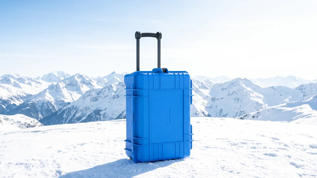
An instrument that moves from the laboratory to a vehicle, or from a warehouse to a field site, does not experience one planned shipment. It experiences dozens of lifts, turns, set-downs, lid openings and short walks every single day. When a carrying case is selected on static volume alone, the same complaints keep appearing: the handle cuts into the palm, the body swings against the leg, a latch pops open, and the payload strikes the inner wall at the instant the case is set down. Portability therefore is not the simple fact of having a handle. It is an engineering system in which human grip, centre of gravity, load path, shell stiffness and cushioning travel all have to work together.
The JUNZHIJIA protection principle is simple: carry loads must travel along a verifiable structural path, and the energy of a drop from carry height must be held inside the range the equipment can survive, instead of using a thick, heavy appearance as a substitute for genuine portable safety. This article moves through grip geometry, single-hand latches, shoulder strap load paths, centre of gravity control and carry-height drop behaviour to show how an everyday carrying case can be defined as something measurable, testable and repeatable for years of service.
Table of Contents
- Why Portable Protection Is a Dynamic System
- Handle Ergonomics and Grip Geometry
- Centre of Gravity, Wrist Moment and Walking Stability
- Single-Hand Latches and Accidental Opening Control
- Shoulder Strap Load Paths and Attachment Design
- Shell, Ribs and Hinge Continuity
- Liner Cushioning and Carry Shock Management
- Sealing, Pressure Equalisation and Short Outdoor Exposure
- Compartment Layout and Fast Access Logic
- Carry-Height Drop Testing and Acceptance Criteria
- Human Factors in Everyday Handling
- Parameter Confirmation, Prototype Testing and Acceptance
- Customisation, Tooling and Case Documentation
- Frequently Asked Questions FAQ
- Conclusion and Related Reading
Why Portable Protection Is a Dynamic System
At rest a carrying case mainly carries its own weight and any stacking load. Once a person walks with it, cyclic acceleration is added on top. Step frequency makes the body rise and fall; sudden stops, kerbs and obstacles add fore-aft and lateral swing. If the loaded case weighs twelve kilograms and a transient peak of roughly twice gravity occurs, the equivalent load reaching the handle boss, the pivot pin and the shell joint region can be far higher than the twelve kilogram static figure. A rated capacity that only says "holds twelve kilograms" is therefore incomplete. It should also state the safety factor applied, the number of repeated lifts the structure is qualified for, and the directions in which the load is applied.
The complete load path starts at the finger contact surface and passes through the grip body, the rotating pivot or soft link, the handle boss, the reinforced shell area, the liner and finally the equipment support face. Any sudden change of section, any sharp corner or any loose joint along that path can become the origin of a fatigue crack. Portable design must also accept the real conditions of use: gloved hands, wet hands, alternating left and right hands, and a lid that is not fully latched. For sensitive instruments it helps to study how shell, liner and operating routine reinforce one another in Precision Instrument Cases, rather than treating portability and shock protection as two unrelated purchasing lines.
A usable engineering definition should list maximum loaded mass, average lifts per day, continuous walking distance, typical step height, the permitted share of one-handed operations and the shock limit of the equipment. When the buyer writes those boundaries into the requirement, the manufacturer can choose handle width, wall thickness and foam density from evidence. When they do not, the supplier can only match a catalogue number to a generic configuration and hope for the best.
Handle Ergonomics and Grip Geometry
Handle comfort is decided by effective grip length, cross-section width and thickness, edge radius, surface friction and the clearance between the hand and the case body. The effective length must allow four fingers of the target user to sit side by side naturally, and winter glove scenarios need additional width on top of that. A grip that is too thin concentrates load onto the finger bones; a grip that is too thick prevents the fingers from closing and reduces the ability to resist slipping. Oval or rounded-rectangle sections usually spread palmar pressure better than a narrow hard square bar, with the loaded side slightly wider and the back side smoothly radiused to limit local tenderness during long carries.
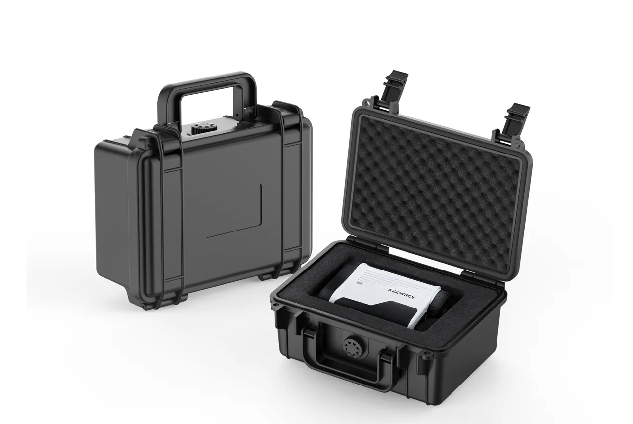
The handle centre should project as closely as possible above the centre of gravity of the loaded case. A rotating handle needs to self-centre once lifted, and once released it must not block the latches. Clearance between the handle and the lid must be verified with the thickest glove and the least favourable hand shape, never with a bare-hand sample alone. Texture adds friction for wet hands, but excessively deep patterns create pressure marks under high load. Soft overmoulding improves touch, yet adhesion loss, tackiness or cracking after oil, ultraviolet exposure and temperature ageing must be assessed before it is approved.
| Grip Item | Suggested Verification | Failure Symptom | Design Adjustment |
|---|---|---|---|
| --- | --- | --- | --- |
| Effective length | Trial grip with different hands and gloves | Little finger unsupported, fingers squeezed | Lengthen the straight grip zone |
| Cross-section shape | Walking test at rated load | Concentrated pain point in the palm | Increase load face and edge radius |
| Anti-slip surface | Dry, wet and oiled glove testing | Excessive grip force required | Adjust texture and material friction |
| Hand clearance | Insert thickest glove and rotate wrist | Knuckles strike shell, no self-centring | Raise handle or enlarge recess |
| Rest position | Repeated lift and set-down cycles | Interferes with latch or pinches hand | Add stop and control return speed |
Centre of Gravity, Wrist Moment and Walking Stability
The complaint that a case "is not heavy but is tiring" usually comes from a centre of gravity offset from the handle. When the horizontal offset between the loaded centre of gravity and the handle centre is e, the wrist must continuously resist an overturning moment roughly equal to the total weight multiplied by e. If heavy components cluster at one end of the body, then even with unchanged total mass the case tilts after lifting, knocks against the legs and lands on one corner first when set down. Designers should build a real mass list covering instruments, cables, spares and document pouches, compute the resultant centre of gravity from each component mass and coordinate, and then confirm it with a suspension test on a prototype case.
The ideal target is not a mechanical pursuit of the geometric centre. It is to bring the loaded centre of gravity close to the grip centre while keeping tolerance for missing accessories or changed consumables during service. High-density foam support blocks, divider positions or accessory pockets can redistribute mass, but sensitive equipment must never be pushed against a weak wall merely to achieve balance. Long instruments need pitch-direction restraint, and dense items such as batteries belong near the case floor and under the handle projection, held in separate closed-cell foam cavities so they cannot repeatedly hammer other contents while walking.
Acceptance can be as simple as suspending the loaded case from the handle and measuring the inclination of the main plane, or as thorough as asking users of different heights to walk a defined route while recording body swing, leg contact frequency and how often they switch hands. If inclination is obvious, check loading position first, then decide whether a second handle or a shoulder strap is needed. A centre of gravity mark printed on the liner loading map helps prevent field staff from moving accessories around and quietly destroying the designed balance.
Single-Hand Latches and Accidental Opening Control
Field work routinely requires one hand to steady equipment or hold a door while the other hand sets the case down and opens the lid. A single-hand latch is not simply a loose latch. It must complete "release preload, pass the over-centre point, free the lid" under a limited thumb or finger-pad force while still retaining enough clamping force when closed. Operating force that is too high invites users to tap the latch shut or close only one side; force that is too low risks being hooked open by clothing, a vehicle edge or the shoulder strap. A sound mechanism gives a clear tactile over-centre feel, a visible closed position and finger space that cannot pinch.
A two-latch case normally still has to be opened latch by latch. "Operable with one hand" means each latch can be completed reliably by the same hand; it does not mean the lid should be opened while the case hangs in mid-air. Latch ears, pivot pins and the shell boss must transfer preload into the region of the seal, otherwise one area is squeezed hard while a distant section still leaks. The mutual constraints between latch, hinge and gasket are explored further in Toolbox Hinge, Latch and Seal Coordination.
Verification must cover new parts, cold-conditioned parts, dust-contaminated parts and parts worn after a defined number of open-close cycles. Record the peak opening force, the peak closing force, whether the latch rebounds and whether the closed indication is unambiguous. If the case must be protected from unauthorised opening in transit, a seal wire hole or padlock eye can be added, provided the structure does not cut into the main latch section and the lock body does not protrude where it can snag.
Shoulder Strap Load Paths and Attachment Design
A shoulder strap frees the hands, but it converts a single handle load into a diagonal pull between two attachment points. During walking, strap tension contains not only the case weight but also a peak component from swing, and the force direction at the ring keeps changing. The most dangerous outcomes are usually bending at the root of the ring boss, cutting of webbing edges and disengagement of a metal hook under side load. A strap eye must not be a thin tab on the side wall; it has to form a continuous load path with side ribs, the case frame rim or through fasteners, and stress concentration has to be controlled.
Attachment position determines how the case sits against the body. Two points set too high let the case tip outward; set too low, the upper edge presses into the torso. Left and right points should let the case hold a slightly outward stable angle so latches, corners and ribs do not rub clothing. A wide shoulder pad must retain enough area under load, its inner friction face must resist slipping, and the adjuster buckle must not fall on the collarbone or neck. If the loaded case exceeds the company single-person handling limit, a strap is not a reason to raise that limit; a second handle, a trolley handle with wheels or a cart is the correct answer.
| Strap Component | Main Load | Key Failure Mode | Prototype Verification |
|---|---|---|---|
| --- | --- | --- | --- |
| Shell anchor boss | Diagonal pull and alternating bending | Whitening and cracking at root | Multi-angle cyclic pull test |
| Quick-release hook | Tension, torsion, side load | Hook mouth opening, accidental release | Worst-attitude static load and shock |
| Webbing stitching | Shear and peel | Skipped stitches, end slip | Rated load cycling and visual check |
| Length adjuster | Friction locking | Slow lengthening while walking | Length retention after vibration |
| Shoulder pad | Surface pressure and sweat | Curling, slipping, hardening | Walking trial with different clothing |
Shell, Ribs and Hinge Continuity
A portable case shell has to balance weight against stiffness. Engineering plastics such as polypropylene gain bending resistance through radii, local ribs and a closed frame rim section rather than by simply thickening the whole wall. Ribs near the handle boss should spread load into a larger shell area; a rib root that is too thick causes sink marks, and one that is too thin cannot transmit force. During design it is worth checking whether the case mouth opens when the handle is pulled upward, whether seal compression changes, and whether the floor visibly sags when fully loaded.
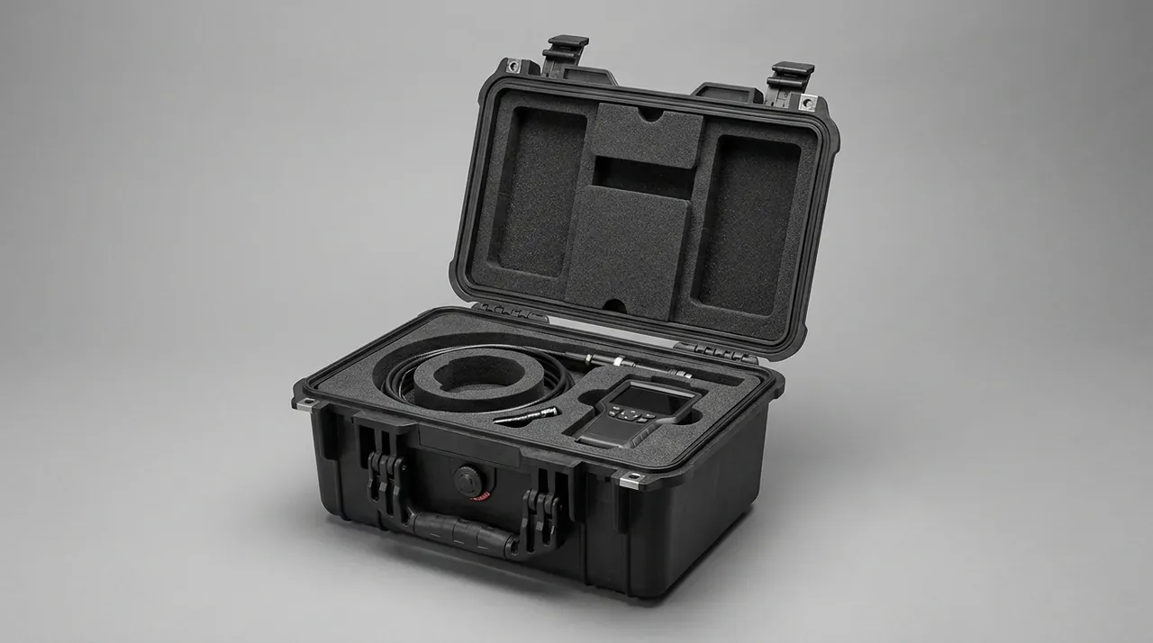
The hinge is both a lid locating element and an important restraint when the case suffers a corner drop. A continuous pin hinge or a multi-point hinge must control axial play, and the lid back-stop must not concentrate all over-travel force at the root of a thin hinge wall. Users do sometimes drag a case along with the lid open, and although that is not a recommended action, a reasonable foreseeable misuse should still appear in the structural risk review. Low-temperature toughness, ultraviolet stability and detergent compatibility of the shell material have to match the application, and resin, filler and moulded condition can be confirmed against Engineering Plastics for Outdoor Cases.
Shell inspection must go beyond surface gloss. Measure case mouth flatness, handle boss fastening torque, pin retention and permanent deformation under rated load. If a weld line on an injection moulded part falls near the handle boss or a strap ear, reduce the risk through flow analysis, gate position or local geometry. Colour masterbatch and regrind ratio must not be allowed to sacrifice toughness in critical load-bearing zones.
Liner Cushioning and Carry Shock Management
Everyday handling shocks most often occur when setting the case down, clipping a door frame, stepping over a kerb or loading a vehicle. Individual pulses may be milder than a high drop, but repetition loosens connectors, drifts calibration and scuffs housings. The liner job is to deliver controlled deceleration and positive location, not to fill every void. Foam thickness, density and loaded area together define the cushioning curve; material that is too soft bottoms out, and material that is too hard barely extends the impact duration.
EPE suits wide bearing areas and economical layered builds, EVA cuts cleanly and presents a tidy surface, and IXPE works where a thin layer of uniform closed cells and better water resistance is needed. Selection should follow equipment mass, permitted peak acceleration, drop height and available cushioning travel, checked with a drop prototype or a cushion curve. The differences in resilience, processing and long-term compression set are set out in EPE Versus EVA Foam for Toolbox Liners.
At minimum the liner must restrain movement in six directions and provide zero-contact zones around protruding knobs, screens, optical windows and connectors. Equipment must never be carried by a fragile interface; bottom support blocks under heavy items should be continuous and replaceable. Lid foam should lightly press the equipment to stop it bouncing, but excessive compression can transfer load into a display. For frequently accessed areas, add a wear-resistant skin, finger pulls and colour coding so a missing tool is visible at a glance and finger digging tears less foam.
Sealing, Pressure Equalisation and Short Outdoor Exposure
When a carrying case moves from indoors to a rainy vehicle or a dusty site, sealing prevents short-term ingress, but an IP rating is only valid when the complete case and a defined test support it. Gasket cross-section, compression ratio, mouth flatness and latch preload decide the result together; simply fitting a thicker strip can make latches hard to close, deform the lid or raise hinge load. If a project claims IP65 or IP67, it should state the reference to IEC 60529 or GB/T 4208, the sample condition, the inspection before and after testing, and whether a pressure valve is included.
Rapid temperature or altitude change creates a pressure differential that can make the lid difficult to open. A pressure equalisation valve allows slow gas exchange while limiting liquid water and particles, and its mounting face must be sealed and must not be covered by the liner. The choice between an automatic and a manual valve depends on how the equipment tolerates moisture vapour, how fast the case must be opened and what maintenance is acceptable; see Pressure Equalisation Valves for Protective Cases. A valve does not replace moisture management: once humid air has entered a warm case, falling temperature can still condense on equipment surfaces.
Site procedures should require wiping the case mouth before opening so grit does not cling to the sealing face, and cleaning only with compatible materials and no sharp tools on the gasket. Periodic checks should look at compression mark continuity, joint separation, permanent set and valve membrane contamination. If daily use only needs shower resistance, it should not be advertised as unlimited immersion; where immersion risk genuinely exists, verify with the target load, aged seals and the real latch condition.
Compartment Layout and Fast Access Logic
Portable efficiency depends not only on being able to lift the case but also on how little rummaging and misfiling happens on arrival. The interior should follow task order: the checklist and main unit visible immediately after opening, frequently used cables in the zone nearest the hand, and small accessories in lidded or clearly bounded pockets. Cavity outlines and colour coding reduce missed items, and QR codes or labels can link serial numbers, calibration dates and the responsible person, provided they never cover a sealing face or rub against equipment.
Heavy items belong near the floor and under the handle projection, sharp tools must be separated from soft cables, and battery terminals must not touch metal accessories. Cable channels should respect the natural bend radius instead of forcing fibre, probe leads or shielded cable into a sharp fold when the lid closes. A document pocket in the lid can hold paper records, but its filled thickness must be evaluated for pressure on the equipment. Removable dividers suit tasks whose kit changes often; custom foam suits high-value instruments with fixed positions. The trade-off is discussed in Case Dividers Versus Custom Foam.
Layout review must use the complete real kit, including chargers, adapters, spares and manuals. Ask a user who has never seen the prototype to pack and retrieve against the list, and watch whether they rotate the equipment, dig with both hands or remove other items first. A genuinely good layout does not show off complicated shapes; it protects weak areas while cutting the number of actions and making a missing part obvious instantly.
Carry-Height Drop Testing and Acceptance Criteria
The starting point for carry-height drop testing comes from real handling: the floor height of the case when the arm hangs naturally, the hand-over height at a vehicle, and the worst attitude when the grip is lost on a step. Testing one flat face is not enough, because a case dropped from the hand usually contacts on a bottom corner first, then rotates so a side edge or a latch strikes second. Select faces by risk: the base, four bottom corners, the handle side, the hinge edge and the latch edge, and state the number of drops per attitude and whether samples accumulate damage.
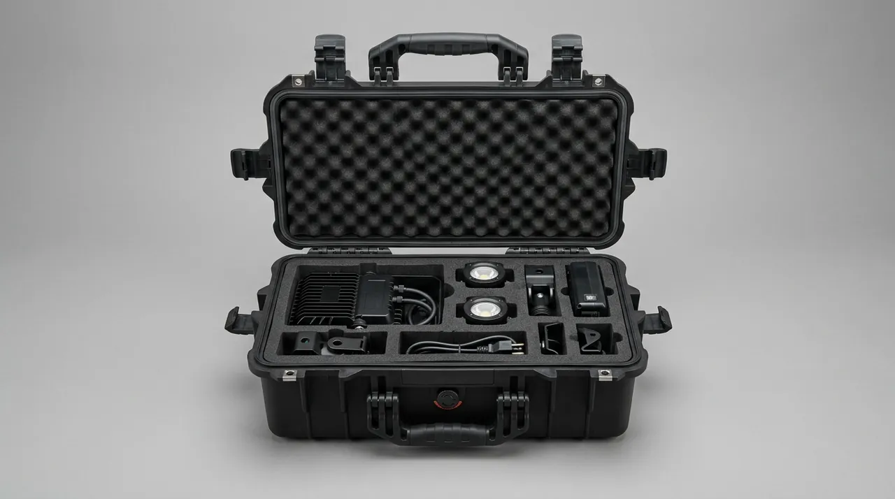
Drop height should not be used on its own as a performance claim. At the same height, equipment mass, liner travel, impact surface and attitude change the response significantly. Three-axis accelerometers on a mass dummy capture peak value, pulse width and velocity change for comparison against the allowed shock of the equipment. Where no fragility data exists, use at least a functional prototype or a fixture of equivalent mass, centre of gravity and stiffness, then inspect appearance, opening, sealing and equipment function after the drop. Transport-level testing can reference ISTA, GB/T 4857 or ASTM D4169, but a standard programme must be tailored to the actual distribution environment rather than using a standard name in place of test conditions.
| Post-Drop Item | Suggested Pass Criterion | Typical Meaning of Failure |
|---|---|---|
| --- | --- | --- |
| Handle and boss | No crack, pull-out or permanent looseness | Load path or material toughness inadequate |
| Latch and mouth | Stays closed and operates normally | Edge stiffness or preload design inadequate |
| Liner location | Equipment clear of wall, foam not bottomed or torn | Cushion travel or bearing area inadequate |
| Equipment response | Function, calibration and connectors normal | Peak shock above fragility level |
| Seal recheck | No unacceptable ingress after target test | Permanent mouth deformation or gasket shift |
Human Factors in Everyday Handling
Even an excellent case can fail through incorrect movement. Companies should require a check after loading that every latch is engaged, the handle has fully returned, strap hooks are closed and nothing is loose outside. Before lifting, take a short trial lift to judge whether weight and balance feel normal. When passing a narrow doorway, avoid striking the latch side against the frame. On stairs keep the case on the outside of the body so it never blocks the view of the feet. Above the single-person handling limit, use a cart or two people; "I can still lift it" is not a safety criterion.
The set-down action matters just as much. Users commonly release the case in the last few centimetres, and that is where a large share of low-height impacts originates. Training should require bending the knees, keeping the base level and making full contact with the ground before letting go, and should forbid resting on a corner and rotating the case along the floor. Inside vehicles the case needs its own anchorage point; a shoulder strap is not a vehicle restraint, and braking loads can far exceed walking design values while hook orientation may not suit vehicle tie-down.
A checklist can be short, as long as it is executable: is loading position correct, are all latches closed, is the weight label readable, is the sealing face clean, is the handle free of cracks and noise, and can the assigned person move it safely. Near-miss records should track which collisions, drops and pinches happen most often, and drive changes to structure or procedure, rather than waiting for damaged equipment and a discussion about blame.
Parameter Confirmation, Prototype Testing and Acceptance
When purchasing carrying cases, the requirement document should start from application conditions instead of listing only outer dimensions and colour. Submit at least the three-dimensional size, mass and estimated centre of gravity of the equipment, fragile areas, permitted shock, daily open-close and handling frequency, temperature and humidity, dust and rain class, chemical contact, strap needs and marking requirements. If the equipment carries a calibration certificate, a sensitive probe or a removable battery, those belong in the interior kit review as well.
Prototype work proceeds in three steps: first verify grip, centre of gravity and shell deformation with a mass fixture; then complete packing, retrieval, human factors and carry-height drops with functional equipment; finally repeat sealing, cycle opening and testing after environmental preconditioning. AQL sampling suits batch appearance and dimensions, but critical load and protection items need first-article confirmation, type testing and batch traceability. Sampling principles and defect classes can be defined with AQL Acceptance for Custom Cases to produce fatal, major and minor defect lists.
| Requirement Field | Quantified Information Required | Acceptance Evidence |
|---|---|---|
| --- | --- | --- |
| Loaded mass | Typical, maximum and offset combinations | Weighing record and balance attitude |
| Grip performance | Glove type, walking distance, allowed discomfort | Trial records from target users |
| Structural strength | Static multiple, cycle count, direction | Handle and strap cycling report |
| Drop protection | Height, attitude, count, impact surface | Acceleration and function check report |
| Sealing capability | Rating, reference, sample condition | Third-party or agreed test record |
| Service life and maintenance | Open-close cycles, replaceable parts list | Cycling test and spare parts document |
Customisation, Tooling and Case Documentation
Custom projects should begin with a payload data package rather than a styling sketch. JUNZHIJIA can design case dimensions, handle and strap mounts, latch quantity, liner compartments and marking positions from the equipment model and the handling boundaries. Where an existing body already satisfies the structural envelope, the better route is a proven shell with a CNC or die-cut liner; injection tooling is only evaluated when centre of gravity, opening direction, interface windows or unit cost at volume cannot be met by a standard case. A tooling review must cover draft angle, rib thickness, weld lines, metal inserts and the tolerance chain, not merely approve a render.
OEM and ODM volume programmes should retain records of material lots, colour tolerance range, critical dimensions, latch force, fastening torque, foam density and bonding process. First-article sealing covers case appearance as well as loaded attitude, accessory list and label template, and any later change must state its effect on centre of gravity, sealing and drop results. Kexin New Materials (Guangdong) Co., Ltd. can supply packing drawings, inspection records, material statements, use and maintenance guidance and contractually agreed test reports with each case, so that correct loading and daily inspection reach every unit in service.
Design for maintenance extends service life considerably. If handles, latches, straps and liners are defined as replaceable parts, they need part numbers, removal and installation instructions and reinspection requirements. After a latch change, recheck preload and sealing; after a liner change, confirm the equipment still clears the wall and that the centre of gravity has not shifted noticeably. Document revisions must be tied to case serial numbers so that an old packing drawing is never used to configure new equipment.
Frequently Asked Questions FAQ
Q: How should the rated load capacity of a carrying case be determined?
A: A rated capacity should never be derived only from a static crush figure for the shell or from the single pull-to-failure value of a handle. The boundary has to be the continuous use of a fully loaded case. Start by listing the main unit, accessories, documents and any spares that may be added later, and derive the maximum loaded mass from that list. Then add the dynamic amplification produced by walking bounce, stepping over kerbs and short emergency stops, and apply this amplified load to the handle boss, pivot pin, strap anchor and case mouth structure. Verification should include a static suspension test at a defined multiple of rated load, repeated lifting at rated load, strap pull in several directions, and a check for cracks, looseness and permanent deformation after cycling. If a supplier offers only a single kilogram figure without stating load position, hold time, cycle count and safety factor, that number cannot be used directly in a risk assessment. The final rating must also defer to the company single-person handling limit, because a structure that survives does not mean a person can safely repeat the lift; above the limit, choose twin handles, wheels or a cart.
Q: Does a softer handle with thicker overmoulding always mean better comfort?
A: No. Comfort comes from a balanced combination of palmar pressure distribution, effective grip length, cross-section shape, friction and hand clearance, not simply from softness. Very soft overmoulding collapses under high load, allowing the rigid inner skeleton to create a new concentrated pressure point, and aged material can become tacky, crack or lose friction in an oily environment. An oversized cross-section stops the fingers from closing properly, so the user has to squeeze harder to resist slipping, which increases fatigue rather than reducing it. The correct method is to take the target loaded weight and have users with different hand sizes carry the case over a defined distance, bare-handed, in the usual work gloves and under wet conditions, while observers record palm pain points, wrist posture, how often hands are swapped and how much the body swings. The overmoulding material also needs confirmation of compatibility with temperature, sweat, cleaning agents and ultraviolet exposure. For heavy cases, increasing grip width and aligning the centre of gravity is usually far more effective than simply adding more soft rubber.
Q: How can I tell whether the internal centre of gravity is correct?
A: First calculate the resultant centre of gravity from the mass and three-dimensional position of every component, then confirm it by suspending a fully loaded prototype. After lifting, the main plane of the case should stay within the agreed inclination and should not keep sagging toward one end or repeatedly knock the side wall against the leg. If removing one frequently used accessory changes the attitude dramatically, the layout is too sensitive to normal use, and the dense main item should be moved closer to the handle projection, or ballast such as batteries and adapters should be repositioned. Adjustment must never eat into cushioning thickness at a fragile area, and heavy parts must not be supported by a small foam area alone. Printing the packing outline and mass hints onto the liner helps keep accessories in their proper places. Acceptance should cover maximum load, minimum typical load and any permitted offset combination, and should include left-handed and right-handed users actually walking, turning and using steps, while recording inclination, swing and which corner touches down first.
Q: Does a single-hand latch reduce protection against accidental opening?
A: One-hand operation and low retention force are not the same thing. A good latch uses leverage and an over-centre mechanism so a finger can release the preload through an acceptable travel, while a definite dead point and sufficient clamping force remain after closing. Protection against accidental opening comes from a recessed layout, guarding ribs, a sensible trigger direction and an unambiguous closed indication, not from raising the opening force without limit. Design verification should measure peak opening and closing force on new parts, cold parts, dust-contaminated parts and parts worn after a defined cycle count, and should check for rebound, half-latching and pinching. Padlock eyes and seal wire holes support access control but must not cut into the main latch section. Operating rules should also state that the case is set down and stable before unlocking, and that unlocking a case hanging in mid-air is forbidden. If staff routinely close only one latch, engineers should investigate force, action sequence and loading interference instead of blaming poor discipline, because sustained one-sided load damages mouth flatness and seal compression.
Q: Why should shoulder strap attachment points not be cut directly into a thin side wall?
A: Strap tension is diagonal and continuously changing, and peaks above the static case weight appear whenever the user walks, turns or steps down. A hole in a thin side wall has little surrounding bearing area, so stress concentration, whitening and cracking appear around the edge, and repeated swing lets fasteners wear the hole oversized. A reliable attachment forms a continuous load path with the case frame, ribs or a backing plate of adequate area, and keeps a metal hook from levering open at the most unfavourable deflection angle. The hole edge needs a smooth contact surface so it cannot cut the webbing, and fasteners must be locking without intruding into the equipment cushioning space. Verification should cover not only axial pull but also cyclic loads combining forward, rearward, upward and torsional directions, followed by inspection for cracks, looseness and any effect on sealing. For a case beyond comfortable single-person handling, a stronger anchor does not solve the human load problem; the handling method itself must change to two people, wheels or a cart.
Q: What drop height and orientations should carry-height testing use?
A: Height must come from real handling actions, not from a round number chosen for marketing. Measure the floor clearance of the case base when the target person carries it naturally, plus the hand-over height at vehicles and the worst attitude when the grip is lost on a step, then set the test value against equipment fragility and risk class. Orientations should include at least the base, the bottom corners, the handle side, the latch edge and the hinge edge, because a case slipping from the hand usually touches a corner first and then rotates into a second impact. State the number of drops per attitude, the impact surface material, whether the same sample accumulates drops, and the mass and centre of gravity of the dummy load. Results are not judged on the shell alone; inspect the handle boss, latches, case mouth, whether the liner bottomed out, equipment function and calibration, and repeat the sealing test if a rating is claimed. Acceleration traces help reveal the hidden failure where the outer case looks intact but the equipment has still been shocked. Standards give a useful framework, but real conditions must be written into the test plan.
Q: Can an IP67 carrying case hold damp equipment for long periods?
A: A water ingress rating must not be read as active dehumidification. IP67 evaluates the entry of external water under agreed conditions; if wet equipment, damp fabric or humid air is closed inside the case, that moisture is sealed in with it. When temperature falls overnight, relative humidity inside rises and condensation can form on metal parts, optics and circuit boards. The correct routine is to dry equipment before packing, complete drying in a controlled environment where necessary, and fit renewable or replaceable desiccant monitored by humidity indicator cards or data loggers. A pressure equalisation valve mainly relieves differential pressure and is not a high-flow dehumidifier. The gasket must stay clean and the valve membrane must not be covered by foam or labels. Before long-term storage, follow the equipment requirements for battery state, lubrication and corrosion protection. If the task repeatedly involves packing wet and unpacking dry, establish a cycle of opening the case to ventilate and replacing the desiccant rather than keeping it permanently sealed. Cases stored in vehicles or coastal depots also deserve more frequent inspection, because daily temperature cycling drives repeated breathing through the seal and any valve, gradually raising the internal moisture load even when the case has never been opened.
Q: What information should be supplied when prototyping a custom liner?
A: Provide a complete item list with the size and mass of every object, three-dimensional models or measured drawings from several views, the centre of gravity and the fragile areas, plus permitted contact zones and zones where pressure is forbidden. State the packing sequence, whether gloves are worn, how often items come out each day, the minimum bend radius of cables, foreseeable accessory changes and any serial numbers or connectors that must stay visible. If the equipment has a defined shock limit, give the permitted peak acceleration and pulse information; otherwise describe past damage and the acceptance method. That input lets the manufacturer choose EPE, EVA or IXPE density, layer thickness, bonding and surface treatment. A prototype must not be judged on whether the cut outline looks attractive; verify it with the full physical kit for six-direction location, finger access, lid compression, centre of gravity and carry-height drops. Sealing documentation should record material lot, critical dimensions, the packing drawing and the label revision, so production units never fit the equipment while losing the intended cushioning travel.
Conclusion and Related Reading
JUNZHIJIA delivers carrying cases as complete handling systems, combining grip, balance, latching, sealed structure and verified drop cushioning, supported by custom liner design, tooling, OEM/ODM and documented first-article acceptance.
Related Reading