

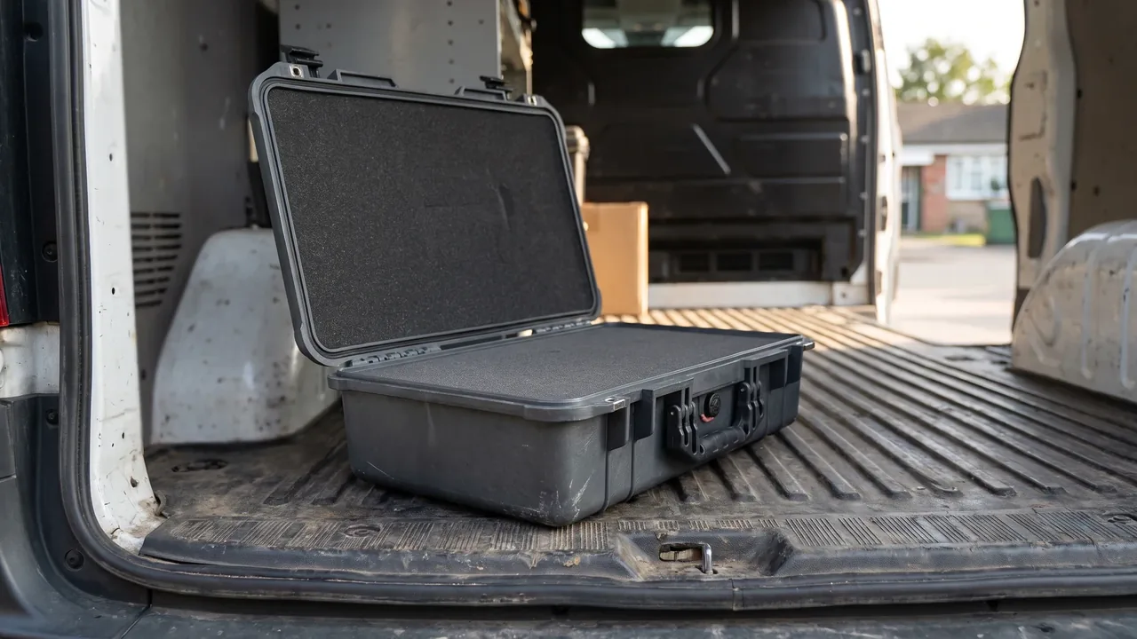
The hardest part of moving a cigarette making machine is not the several-tonne machine itself, but the rolling units and feed wheels that come off it. A rolling unit carries the plug former, the plug wrap reel and the seam paper reel, and any uneven load can crease, distort or permanently fold 20–30 µm paper. The feed wheel and transfer wheel pair are matched to micron-level tolerance on their tooth flanks and tapers; a single knock means they go back for regrinding. These assemblies sit inside the tobacco monopoly traceability system, so a damaged unit in transit is not something a spare part order can easily replace.
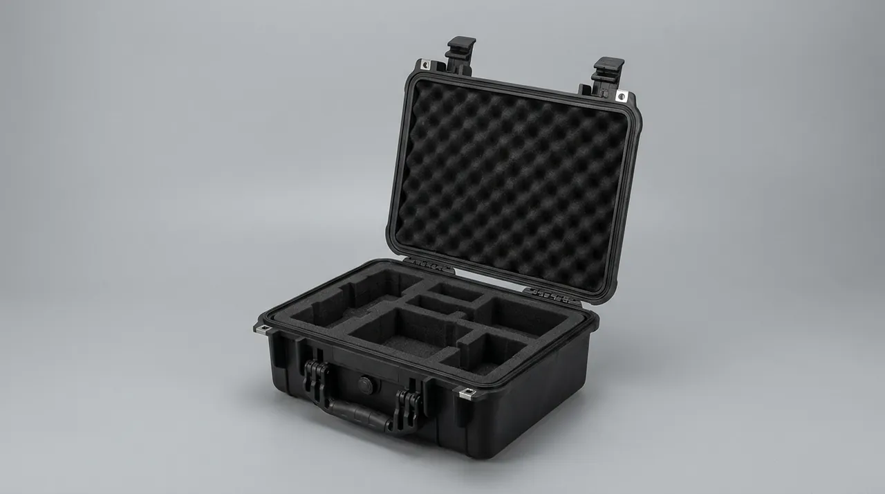
JUNZHIJIA designs cigarette making machine cases around one principle: zero pressure on thin paper, zero impact on precision parts, zero displacement of the whole case. Pressure-free partitioned cavities protect plug wrap and seam paper, a centring skeleton holds the plug former and cutter frame, and lockable axial stops hold the feed and transfer wheels, so the assembly datum survives stacking, drop handling and long sea freight. The case is produced by Kexin New Materials (Guangdong) Co., Ltd., delivered as one package covering tool opening, cavity partitioning and the accompanying document set.
Table of Contents
- Eliminating Static Adhesion in the Rolling Unit and Bonding the Inserts
- Pressure-Free Packing Design for 20-30 µm Plug Wrap and Seam Paper
- Reel End-Face Parallelism and Axial Deformation During Handling
- Tracing Plug Former Misregistration Against Seam Width Variation
- Preserving Feed Wheel and Transfer Wheel Tooth Clearance Through Transit
- Cutter Edge Rolling and Ragged Smoking Rod Ends
- Vibration and Standstill Protection for 8000 Cigarettes per Minute Duty
- Flavouring Residue and Food-Grade Cleanliness Constraints
- Moisture Pickup and Coil Distortion Across Climate Zones
- Rust Protection for Reel Shafts, Cutter Frames and Guides
- Lifting Capacity and Stack Tier Constraints Feeding Back Into Design
- Arrival Inspection: End-Face Impressions, Coaxiality and Paper Feel
- Frequently Asked Questions FAQ
- Conclusion and Related Reading
Eliminating Static Adhesion in the Rolling Unit and Bonding the Inserts
Once plug wrap and seam paper reels are removed from their cores during dismantling, the most common sight is a set of plies that will not separate. Friction between the film liner and the paper surface generates charge, and because thin paper has high dielectric impedance the charge does not dissipate; adjacent plies bond electrostatically. Transit vibration repeatedly breaks and reforms that bond, and every cycle raises a slight burr and delaminates an edge. After installation the paper web shows abrupt tension changes, uneven seam overlap width, and in the worst case a tear right at the seam.
Three parallel measures remove this. First, liner material: the lining should have a surface resistivity in the 10^9 to 10^11 ohm band, a dissipative or conductive grade rather than fully insulating polyethylene film; the foam should have a closed-cell structure with a wipeable skin so open pores do not become a shared carrier for charge and moisture. Second, insert bonding: an equipotential path must be established between the rolling unit housing and the metal inserts inside the case, and the grounding terminal outside has to reach the vehicle or workstation equipotential bar, otherwise charge is merely isolated rather than drained. Third, environmental control: keep the packing and unpacking area between 40% and 60% relative humidity, because rising humidity sharply lowers the surface resistance of thin paper.
| Symptom | Root cause | Protective measure | Acceptance criterion |
|---|---|---|---|
| --- | --- | --- | --- |
| Plies bond and tear on unwinding | Film friction charge with no drain path | Switch to dissipative liner | No tearing on unwind |
| Edge burr | Repeated bond-break friction | Control humidity, avoid pressure | No visible burr at the edge |
| Seam overlap width varies randomly | Uneven static tension on the web | Bond inserts equipotentially | Overlap width within tolerance over 10 reels |
| Localised discharge specks | Concentrated potential difference | Dissipative liner throughout | No discharge burn marks |
Static and humidity push each other up, and many sites treat them as separate problems: they replace the desiccant, the indicator card reads normal, and the plies still bond. The diagnostic is to measure potential difference between the paper surface and the case insert with a grounding meter; a measurable potential the moment the case is opened means the drain path was never real, and dehumidification alone will not help. For the equipotential principle applied to enclosures in general, the bonding approach in electrical enclosure installation practice transfers directly.
Pressure-Free Packing Design for 20-30 µm Plug Wrap and Seam Paper
Plug wrap typically runs at 20–30 g/m² and 20–30 µm thick; seam paper is somewhat heavier but still far below what packaging materials normally tolerate in compression. That thickness leads to one conclusion: any scheme that trades pressure for location will damage the paper surface directly. Tightening a strap, bearing against a partition, or wrapping film under tension all leave an impression on the reel end face that opens into a permanent straight crease, and that crease sits exactly where the plug wrap overlaps during machine running, so every subsequent rod repeats the same stress.
Pressure-free design has three points. First, cavity size derives from the core, not from the reel outside diameter. Leave 3–5 mm of circumferential clearance between cavity and reel; that clearance absorbs transit displacement and moisture-driven swelling, and the larger it is the lower the pressure on the paper. Second, location in the radial direction comes from self-weight, not radial clamping, so in any transit attitude the normal force on the paper stays close to its own weight. Third, partition the cavities so different specs and batches never share one volume. For the clearance convention applied to reel stock, the approach in paper roll transport case design is directly comparable.
| Specification | Core bore | Reel outside diameter | Circumferential clearance | End-face support |
|---|---|---|---|---|
| --- | --- | --- | --- | --- |
| Standard plug wrap reel | 76 mm class | Set by machine spec | 4 mm | Flexible end pad, no contact on the wrap face |
| Seam paper reel | 25 mm class | Smaller | 3 mm | Annular soft end pad |
| Reel shaft assembly | Per model | Axial stop blocks | 1–2 mm axial | Stop block with elastic liner |
Liner thickness and density follow the same logic. Thin paper parts suit a softer open-cell foam at 15–25 mm, which attenuates transit vibration yet does not pass stack load into the paper face. High-density closed-cell foam should be avoided here, because its rebound directs the stacking load along the cavity wall into the reel edge. Where the trade-off between foam structures is unclear, the rebound and absorption differences in EPE and EVA foam toolbox comparisons are worth reading first.
Reel End-Face Parallelism and Axial Deformation During Handling
Once the reel is on the machine, end-face parallelism decides whether the web runs straight. A non-parallel face means the plies vary in thickness across the axis, so one side of the web pays out before the other and a cross-web tension difference develops, showing up as waviness, tracking error and a skewed overlap seam. The handling step that destroys parallelism is rarely vibration; it is axial force from lifting and stacking. One wire rope or one sling taking uneven load can cone the reel within seconds, and that deformation does not come back.
Three hard requirements apply to the reel cavity. First, the end face may only receive distributed flexible support: end pads should be annular or segmented, covering at least 15 mm of the end face width circumferentially, so there is no single point pushing against a whole face. Second, the reel shaft must be located at both ends during packing; with single-end location the reel still has axial freedom and migrates back and forth under vibration, leaving relative sliding marks. Third, lifting points and centre of gravity must be marked outside the case, so the sling approaches vertical rather than pulling an axial component into the reel.

| Defect | What the floor sees | Attribution | Corrective action |
|---|---|---|---|
| --- | --- | --- | --- |
| Coned end face | Web tracks and waves after pay-off | Slant lift or axial load | Mark centre of gravity, lift vertically |
| Single-side impression | One side of the web wrinkles | End pad contact too narrow | Switch to segmented annular pad |
| Relative ply migration marks | Circular friction marks on the face | Single-end location, too much axial slack | Dual-end stops with 1–2 mm slack |
| Loose outer plies | Outer edge lifts at the face | Excessive humidity, ply drying out | Control humidity, use indicator card |
Tracing Plug Former Misregistration Against Seam Width Variation
The plug former sets the accuracy of the strand. It spreads the incoming tobacco into a uniform layer which the plug wrap then encloses, and the overlap seam sits directly opposite the former outlet. When a line reports uneven overlap seam width, the first instinct is to adjust the paper feed, but a large share of those faults trace back to the former condition after transport.
Transit disturbs a former along three paths. First, local plastic distortion: wall thickness around the drum is not perfectly uniform, so when it lands on the cradle ring the reaction points fall on a thin-wall zone and sustained static load turns it very slightly out of round. Second, coaxiality loss between bearing housing and drum: if the three-point support is not coplanar, clamping forces the drum axis off line, and running axial play makes the overlap seam breathe. Third, contamination of the working surface: rust inhibitor, grease or adhesive residue from packing builds local adhesion that lifts fibres off the strand and thickens the web where it passes.
The case therefore applies three things to the former: three-point centring with adjustable coplanarity verification, axial clearance for thermal expansion that is never closed up, and an inert barrier over the working surface with no rust inhibitor permitted to touch it. Preserving coaxiality here mirrors the approach in CNC spindle cases.
| Fault symptom | Transit related | Diagnostic order | Action |
|---|---|---|---|
| --- | --- | --- | --- |
| Seam width varies cyclically | Possibly | Measure drum radial runout first | Return the drum if runout exceeds limit |
| Periodic stiction of drum | Possibly | Check cradle coplanarity | Re-shim the support |
| Local strand fuzzing | Possibly | Look for debris on the drum face | Clean and re-verify the barrier |
| Web tracking direction random | Less likely | Check reel end-face parallelism | Change reel and re-inspect the face |
| Overall strand too thin | No | Review feed rate setting | Process side adjustment |
Preserving Feed Wheel and Transfer Wheel Tooth Clearance Through Transit
The feed wheel meters tobacco onto the strand; the transfer wheel passes the formed rods along the sequence. Both carry tooth flanks and tapers finished to a matched pair, and those surfaces decide whether every rod weighs the same. On dismantling they are usually removed individually and packed separately from the frame because they are vulnerable to both load and contact: a dent in the tooth flank shreds fibre at every rotation, and a slight taper distortion changes the running clearance, producing binding or slip.
The key is to create no relative motion. Wheel and case must be centred at multiple points so vibration cannot make the wheel rock inside the cavity; rocking loads a very small flank area repeatedly and leaves burnished patches. Shaft shoulders must stay clear of hard partitions, because a shoulder high point introduces single-side preload and hides the true assembled condition. Desiccant bags, manuals and labels belong in a separate accessory cavity and must never be packed between the wheel and its liner. Transport attitude matters as much as restraint: toothed and tapered wheels travel axis-horizontal with clear space above the tooth line, and side rolling or inverted placement is prohibited because those attitudes let loose items rest on the tooth face. Support stiffness for drum-type parts follows the reasoning in conveyor roller support and cushioning design.
| Check item | Method | Acceptance criterion | Common nonconformity |
|---|---|---|---|
| --- | --- | --- | --- |
| Tooth flank integrity | Visual with side light | No dents, no burnish, no debris | Relative migration inside the cavity |
| Taper generatrix | Template comparison | No distortion, no step | Single-side preload |
| Running clearance | Hand rotate after assembly | No binding, no preferential wear | Centring not verified |
| Position retention | Re-check after light shaking | Position unchanged | No axial stop |
Cutter Edge Rolling and Ragged Smoking Rod Ends
The flying knife is a high-consumable wear part. Its edge is thin and hard, which makes it both excellent and fragile: it resists abrasion but chips and rolls readily. On the floor, a failed knife shows as fuzzy rod ends, drawn fibres and an uneven cut, and a badly chipped edge can throw metal fragments into the machine. Transit affects it in two ways: point impact on the edge during vibration, and relative movement inside the package letting edges knock against each other or against a hard partition.
The case answers with suspended fixing combined with edge orientation constraint. Knives are held in a purpose-made clamp or bush so the edge faces no direction in which relative sliding can occur. The cavity allows clearance only in the positive load direction and provides a hard stop in the reverse direction, so vibration and impact are consumed by the stop rather than passed into the edge. The packing record notes edge condition and replacement date so arrival inspection can compare directly and avoid confusing transit damage with ordinary wear. Rolling has a clear judgement rule: when a continuous dull band wider than 0.3 mm appears, or the edge line is visibly off, replace the knife rather than continuing to sharpen, because over-sharpening thins the edge and makes chipping more likely.

| Symptom | Attribution | Action | Preventive measure |
|---|---|---|---|
| --- | --- | --- | --- |
| Fuzzy or drawn rod ends | Micro-chipping or dulling of the edge | Change the knife | Suspended edge fixing, positive clearance only |
| Visible edge chipping | Point impact in transit | Stop use and record | Clamp fixing, no hard contact |
| Cyclic variation in cut flatness | Cutter frame positioning loosened | Re-verify frame alignment | Cutter frame inside the centred cavity |
| Metal fragments in the cavity | Chip not replaced in time | Full clean-down | Visual check of every knife before packing |
Because the knife is a consumable item rather than a machined assembly, the packing record should also state how many knives were shipped and how many were replaced on arrival, so a chipped edge can be charged to handling rather than to the sharpening standard used at the workshop.
Vibration and Standstill Protection for 8000 Cigarettes per Minute Duty
A cigarette making machine is high-speed equipment; the complete machine can run at 8000 cigarettes per minute and beyond. Once the rolling unit is removed and packed on its own it loses the locating datum and the damping environment it had on the frame, so the vibration and shock it sees in transit can exceed what it experiences in service. Two input classes dominate: high-frequency low-amplitude vibration from road surface and tyres, and low-frequency high-amplitude shock from throwing, dropping and forklift work.
The response is a layered build-up. The inner layer is soft foam conforming to the part face for high-frequency attenuation. The middle layer is a formed carrier that limits relative displacement inside the cavity and absorbs mid-frequency vibration. The outer shell and load-bearing structure take low-frequency impact and stacking load. The stiffness gradient must not be inverted: if the shell is stiff and the liner soft, impact energy is absorbed before it reaches the thin paper; if the inner layer is stiffer than the shell, energy bypasses the liner and strikes the part face directly. Leave an explicit load path between the partitioned carriers and the shell rather than letting a floating liner strike the wall cyclically.
Standstill protection is separate. Tobacco strand and flavouring residue left inside the rolling unit will cake and soften during long storage, and local hard points then bear against the drum face. The case does not solve long-term storage, but the accompanying documents state the time limit for production after opening and include the residue clearing sequence.
| Input type | Typical source | Band effect | Design response |
|---|---|---|---|
| --- | --- | --- | --- |
| High-frequency vibration | Road surface, tyres | Part face micromotion, interface wear | Face-conforming soft foam |
| Mid-frequency vibration | Vehicle resonance, engine | Relative liner displacement | Formed carrier limiting degrees of freedom |
| Low-frequency shock | Throwing, dropping, forklift | Structural load on the whole part | Load beams and shell take the load directly |
| Stacking load | Weight of cases above | Local floor deflection | Bottom load structure and tier marking |
Flavouring Residue and Food-Grade Cleanliness Constraints
Parts on the flavouring and liquid dosing paths fall under both tobacco monopoly rules and food-grade cleanliness requirements, and their packing requirements differ completely from ordinary machine parts. First, traceability: every cleaning and packing action needs a record covering part number, batch, cleaning method, drying verification, packer and inspector. Second, no migration and no adsorption: packaging must not adsorb flavour components and must not emit odour to the part; textile liners should be avoided because their porous fibres trap volatile compounds. Third, complete dryness: residual water after cleaning is both a microbiological risk and the direct cause of corrosion on adjacent parts and moisture pickup in paper components, so drying must be verified and recorded rather than judged by eye. The practical test is simple: a clean part inspected at the case opening should smell only of its own residue, never of the packaging.
| Regulatory concern | Frequent nonconformity | Measure at the packaging level |
|---|---|---|
| --- | --- | --- |
| Food-grade cleanliness | Liner adsorbs flavour and gains weight | Inert, non-migrating foam; no textile layer |
| Monopoly traceability | Incomplete records, unclear part numbers | Full traceability chain in the documents |
| Microbial residue | Not fully dried after cleaning | Drying verification record plus opening time limit |
| Odour migration | Odour-bearing rust inhibitor or volatile agent | Ban scented inhibitors and slow-releasing agents |
| Cross contamination | Mixed with non-food-grade parts | Separate cavity, separate accessory bag |
These assemblies may not be arbitrarily modified under regulation, so the case should make it impractical to open and casually reassemble: a numbered seal combined with lockable latches serves both tamper evidence and authentication. The seal number binds to the packing list, and a broken seal ends the handover chain. Reusable versions of that traceability approach are described in label and asset tracking practice.
Moisture Pickup and Coil Distortion Across Climate Zones
Plug wrap and seam paper are highly humidity-sensitive. As relative humidity rises from 45% to 75%, the tensile strength of thin paper drops noticeably, the surface turns from firm to soft, and the reel face curls. If the reel is still under load at that point, plies bond and mark permanently. Over-drying pushes the other way, making the paper brittle and prone to edge cracking during unwinding.
Cross-zone transport has to handle three moisture sources: ingress through case seams and breather valves, release of residual moisture already inside the case, and condensation caused by temperature gradients. Desiccant and a humidity indicator card go inside, with the desiccant in a structured bag fixed where it cannot touch any part face, so vibration cannot slide it onto the paper. Condensation control is mostly about temperature gradient, not humidity level: packing straight from a cold store, or standing on a hot road surface for an extended period, can produce condensation inside a sealed case.
| Symptom | Moisture cause | Handling | Prevention |
|---|---|---|---|
| --- | --- | --- | --- |
| Face curling and dishing | High humidity or condensation | Restore temperature gradually, then assess | Humidity indication and desiccant throughout |
| Plies bonded and softened | High humidity plus load | Hold the reel out of production | Pressure-free packing, partitioned cavities |
| Edge cracking | Excessive dryness | Raise ambient humidity | Avoid over-drying |
| Ring-shaped water stain | Condensation | Record and isolate the reel | Control the temperature gradient |
| Indicator card out of range | Route humidity beyond the chosen scale | Photograph first, then open | Match desiccant grade to the route |
Place the indicator card where it best represents the average condition inside the cavity rather than tight against a wall or the floor, because readings taken against the wall are biased toward the external environment and lead to false conclusions. For graded approaches to desiccant and card ranges, the case classification logic in warehouse stacking and moisture control practice can be adapted.
Rust Protection for Reel Shafts, Cutter Frames and Guides
Reel shafts, cutter frames and guides are the most numerous and among the most precisely machined parts on the rolling unit, and most are stainless or plated steel. Their problem is not rust itself but the step immediately before it: surface damage and contamination. Once a protective film is scratched, the scratch becomes the initiation site for electrochemical corrosion, and once the film is breached, humidity forms condensation there and corrosion grows from a point into an area.
The strategy is film, shielding and dryness. Parts get a continuous protective film, every sharp edge gets an individual sleeve, shaft-type parts get end-face dust caps so axial dust migration cannot settle on mating surfaces, and long parts such as guides and cutter frames occupy their own cavity rather than sharing volume with loose fragments. Fasteners and springs go in a separate accessory cavity, individually bagged. Arrival judgements need an explicit basis: a uniform hazy discoloration on plating or stainless steel is a normal surface response to long high-humidity exposure and is not graded as corrosion, whereas point corrosion, corrosion extending from a coating breach, or rust traces along a mating surface is graded as nonconforming and traced back.
| Part category | Main damage form | Protective measure | Arrival criterion |
|---|---|---|---|
| --- | --- | --- | --- |
| Reel shaft | Corrosion on mating and end faces | Film, end dust cap, dedicated cavity | No point corrosion, no spreading |
| Cutter frame | Edge damage, corrosion on locating face | Edge sleeve, individually wrapped | Locating face clean, edges unmarked |
| Guide rail | Scoring and pitting of the sliding face | Protective film, no mixed packing | Sliding face bright, no pitting |
| Fasteners and springs | Thread corrosion, stress corrosion | Sealed bag in the desiccant cavity | Threads free of corrosion, no brittleness |
Lifting Capacity and Stack Tier Constraints Feeding Back Into Design
A case like this is easily treated as something to be lifted, when in fact it is also a container for heavy items: a rolling unit plus paper reels can reach tens to hundreds of kilograms gross. The load capacity in turn limits stack tiers, forklift selection and aisle width, which produces a reverse constraint chain running from the bottom up: case floor capacity, permitted stack tiers, height per tier, vehicle loading plan, and finally the unloading method on site.
The load path is what matters. If the case bottom is a single thin panel, the weight of stacked cases deflects that panel and transmits into the cavity floor, pressing directly on the reel end faces and the lower edge of the former. The correct approach is load beams or a full pallet base that carry the load along the beams to the underside of the case and the vehicle bed, so the cavity floor carries only the parts' own weight. The case exterior must be marked with the maximum stack tier, gross mass, centre of gravity and lifting points, and those four values belong together; leaving one out makes the marking unusable. Marking and load-transfer conventions can be cross-checked against stackable case height limits.
| Reverse constraint step | Design input | Requirement passed downstream |
|---|---|---|
| --- | --- | --- |
| Case floor capacity | Permitted stack tiers and gross mass | Floor deflection limit |
| Centre of gravity | Part distribution inside the cavity | Lifting points and sling angle |
| Case resistance to side tilt | Vehicle braking and cornering duty | Tier limit and no-side-roll marking |
| Forklift handling | Bottom fork entry or lifting aperture | Forklift type and work cell dimensions |
Site work must follow the exterior marking. Stacking beyond the marked tier, placing a flat case on its side, or lifting from unmarked points all fall outside the packaging design boundary.
Arrival Inspection: End-Face Impressions, Coaxiality and Paper Feel
The purpose of arrival inspection is to separate transit damage from damage that existed before packing. Without packing photographs and records, a single impression on a reel could be attributed either to transit or to the packing bench, and responsibility becomes unassignable. Inspection therefore follows a fixed sequence, and photographs come before opening.
Step one examines the outer case: damage, water marks and impact marks, and reads the humidity indicator card, recording the value. Step two opens in the prescribed order and photographs every layer so that liners, accessories and part faces are all covered. Step three re-checks reel end faces, the rolling unit drum, knife edges and feed wheel tooth flanks. Touch is a criterion too: press the paper surface lightly with a fingertip, and a slow recovery that leaves a crease means pressure or moisture damage. Where high-grade gauging is included, the acceptance checklist format in precision instrument cases can be reused.
| No. | Inspection item | Method | Acceptance criterion |
|---|---|---|---|
| --- | --- | --- | --- |
| 1 | Outer case condition | Visual plus photograph | No damage, no water marks |
| 2 | Humidity reading | Read indicator card | Within the calibrated range |
| 3 | Reel end face | Visual plus fingertip press | No impression, no crease |
| 4 | Rolling unit drum | Hand rotate one turn with side light | No distortion, no play, no stiction |
| 5 | Knife edge | Visual against packing record | No chipping, no rolling |
| 6 | Feed wheel tooth flank | Visual with side light | No dents, no burnish |
| 7 | Accompanying documents | Count and reconcile | Packing list, part numbers, records complete |
Any nonconformity should be recorded in writing and notified to the supplier; repairing it on the spot and releasing it should be avoided, because a site repair changes the original state and removes the basis for later responsibility decisions.
Frequently Asked Questions FAQ
Q: What are the most common failures for plug wrap and seam paper reels in transit?
A: Three failure families dominate. The first is pressure creasing: if a reel is pushed directly by a hard partition during transport, the plies take an impression on the end face, and the paper opens with a permanent straight crease. On the machine that crease sits exactly where the plug wrap overlap seam is formed, so the same location is re-stressed on every rod and eventually tears. The second is electrostatic ply bonding: friction between film and paper charges the surface, adjacent plies attract each other, and unwinding produces tears and multi-ply pull-out. The third is moisture distortion, where high humidity or condensation softens the thin paper, the end face curls and the tracking error rises sharply. The case answers with one cavity per reel, cavity walls that never touch the paper face, and a readable humidity indicator card inside, and every reel is checked for core diameter, end-face flatness and edge condition at the packing bench rather than being assessed on arrival alone. Reels of different width are never stacked on a common core, because the offset load breaks the flatness that the whole design is protecting.
Q: Why does the plug former need its own centred cavity instead of sharing space with the cutter frame?
A: The working surface of the plug former is a thin-walled aluminium or engineering polymer drum whose coaxiality and radial runout directly determine strand thickness consistency, so any eccentric load in transit can leave a permanent plastic deformation that does not recover after installation. The cutter frame is equally precision, but its failure mode is a clearance change, which is normally repairable by resetting and locking the screws; once the former drum has been pressed out of round, the whole roller set goes back for repair. The case therefore places the former in a dedicated centring cavity with a three-point support ring around the drum waist, leaves axial clearance for thermal expansion instead of closing it up, and fixes the assembly direction as axial withdrawal, so the drum mouth is never knocked by an angled insertion during unpacking. A record of radial runout at packing gives the arrival inspector a reference value, so transport-induced ovality can be separated from the runout the drum already had when it left the workshop.
Q: What is the core problem for toothed and tapered wheels such as feed and transfer wheels?
A: The core requirement is that the contact surface must never see a point load. The tooth flanks and tapers of feed and transfer wheels are matched together, so once a hard particle presses a dent into the flank, that point keeps dragging the strand during every rotation, producing fluffed tobacco and a spread in rod hardness. The wheel bodies themselves are often light alloy or engineering polymer, so their resistance to impact is far below that of steel. The case keeps wheels unstacked and not tight against each other, separates the shaft shoulder from the hub with dowel pins or shaped spacers, and forbids any freely moving desiccant bag from pressing on the wheel face. Wheel attitude is controlled too, with axis-horizontal shipping marked flat only, so no loose item inside can end up resting on the tooth flank. Before sealing, each wheel is rotated by hand through a full turn to confirm free running, and that check is repeated at opening so a change in feel is treated as transit damage rather than normal wear.
Q: How many tiers can a loaded rolling unit case be stacked to during transport?
A: It depends on the case floor capacity and on the stacking height limit, and in-mill transfer and logistics transhipment are two different duty conditions. The tier count must be stated by the packer for the actual case type, and multi-tier stacking is only acceptable when the loaded case stays within that tier count and the bottom case shows no floor deflection under the weight above. The case carries load beams or a load-bearing pallet so weight transfers directly to the vehicle bed rather than through the case walls, which is what keeps the load path away from the paper. Because the floor deflection limit and the tier count are one decision rather than two, adding a tier changes the whole stack arrangement, so the marked tier is a design output and not a field adjustment. Site teams must work to the marked maximum stack tier, single-case mass and centre of gravity, and stacking beyond the tier is a misuse outside the packaging design boundary rather than a case failure, so responsibility stays with the stacking party.
Q: How should the humidity indicator card be read, and does an out-of-range reading mean you must open immediately?
A: Start by matching the colour of the indicator region against the calibrated humidity points printed on the card. Different routes need different card ranges: short inland road legs need only a low-range card, while sea containers or tropical transfers need a full-range card paired with silica gel desiccant. An out-of-range reading does not mean the case must be opened at once. The correct sequence is to record the reading and the opening time, photograph the closed case first, then dismantle in the prescribed order, so transit moisture can be told apart from a sharp humidity rise in the unpacking area. It also helps to read the card from at least two positions, because a single point near the roof or the floor describes one corner rather than the whole cavity, and a strong gradient between them means the contents were conditioned unevenly. If the paper face is already softening and sagging, hold the entire reel out of production and assess it separately rather than running it on the line and blaming the material.
Q: What extra requirements apply to flavouring and dosing components packed in the case?
A: The extra requirements centre on cleanliness and residue control. Flavouring residues are mostly volatile fragrance in a glycerine and propylene glycol carrier, which can swell and adsorb into packaging, and some low-molecular-weight plastics gain weight and distort after long contact. These parts also sit under food-grade and tobacco monopoly regulation, so they need traceable records before dispatch. The case uses an inert, non-migrating polymer foam and no textile layer that could adsorb fragrance; parts must be completely dry after cleaning before packing; no odour-bearing rust inhibitor goes inside; and the accompanying documents include cleaning records, part numbers, batch data and inspector signatures, with the cavity kept separate from any non-food-grade part. Drying is recorded rather than asserted, with a stated method and duration, and the case interior carries no odour-masking agent that would hide a residual odour at unpacking. Where a part has a defined shelf life, the packing date and the earliest use date travel with the documents, because a case opened after that window no longer proves anything about its contents.
Q: Which acceptance actions must be completed before handover is considered finished?
A: At least five steps. First, the outer case condition: look for damage, water marks and impact marks, and record the humidity indicator reading. Second, photograph comparison: photograph during opening and compare layer by layer with the packing photographs taken at the packing bench. Third, reel end faces: confirm no impressions, no creases and no moisture softening. Fourth, the rolling unit: confirm no drum distortion, no axial play and that the centring support has not been forced open. Fifth, documents: confirm the packing list, part numbers and inspection records are complete. One more point matters on these machines: the seal number on the case must match the packing list before anything is opened, because an already-broken seal means the handover chain ended earlier and every finding after it is disputed. Any nonconformity should be recorded and notified to the supplier, and on-site repair before release should be avoided because it destroys the evidence needed for responsibility decisions. The same rule applies to the moisture reading: record the number, not a verbal description of the card colour, because the colour band is interpreted differently between sites and shifts.
Q: Why can a protection case for this equipment not copy a general machinery parts case?
A: The differences come from two constraints: thin paper components, and food and tobacco regulation. A general machinery case assumes the protected part can take uniform pressure, so parts may be stacked as a block and separated by rigid partitions. Plug wrap and seam paper are the opposite: at 20–30 µm any point load leaves a permanent deformation, so stacking is itself a damage source and partitions must be flexible and clear of the paper face. Second, cigarette machine parts sit under monopoly and food-grade cleanliness requirements, so liner material selection, cleaning records and traceability documents must all survive an audit, and that cannot be solved by adding one more liner. A case of this type therefore has to be designed as a complete system: cavity partitioning, pressure-free lining, support method and the document set together.
Conclusion and Related Reading
Rolling units and feed wheels set the capacity ceiling of a cigarette machine and are its most fragile pair in transit. JUNZHIJIA designs each cavity around the part shape, delivering pressure-free paper packing, precision centring and the document set as one package.
Related Reading