


A depalletizer sits at the head of the line and carries three simultaneous requirements: high speed, high positioning accuracy and high cleanliness. The grab fixture completes four motions, descend, grip, lift and traverse, inside a single layer cycle of 0.8 s to 2.5 s, so the straightness of the guide system sets the lateral alignment achieved against a bottle stack or carton stack. Vacuum cups and clamp plates lose grip reliability the moment their contact surfaces take a score or a flattening. Lift columns travel 2,000 mm to 3,000 mm and behave as slender load-bearing members. The transport damage that matters most is also the easiest to overlook: low-energy but long-duration vibration combined with poor restraint, producing micro-deformation that never shows as an obvious break - a compression mark on a guide column from a timber corner, a collapsed cup lip where cups were stacked, a changed preload inside a cam indexer after a drop. A more dependable approach is to split the shipment into packaging units under four rules: graded vibration limits, zero pressure on contact surfaces, multi-point support for long parts, and independent isolation for electrical gear, rather than bundling the machine into a few generic crates. The sections below cover fixture guides, end-of-arm tooling, lift mechanisms, drive components, and sensing and pneumatic hardware, with structure, restraint method, marking and arrival checks that can be attached to a component case technical agreement.
Depalletizers normally ship in a decomposed state: grab fixture assembly, lift column with counterweight, frame crossbeams, layer pusher mechanism, conveyor sections, pneumatic control box and electrical cabinet form six to nine packing units, and ocean orders frequently add separate crates for servo motors and cam indexers. Once the unit count rises, the question of what may sit on top of what becomes the most common site error. The aluminium fixture frame is the lightest item yet often lands at the bottom, while the valve manifold and light curtain, the smallest items, get pushed in beside heavy parts as void fill. The following discussion ranks components by sensitivity, states clearly which items may never be compressed or struck, then covers structure and documentation, and closes with a checklist that a receiving team can execute directly. The same end-of-arm protection problem appears on other high-speed pick-and-place equipment, as described in vibration and ESD control for semiconductor test handler cases.
Table of Contents
- Fixture System Architecture and Transit Weak Points
- Holding Straightness in Guide Columns and Linear Rail Sets
- Contact-Free Packaging for Vacuum Cups, Clamp Plates and Sweep Bars
- Deflection Control for Lift Columns and Long-Stroke Structures
- Compartment Fixing for Cam Indexers, Linkages and Chain Drives
- Isolation of Servo Motors, Gearboxes and Timing Pulleys
- Shock and Static Protection for Photoelectric, Encoder and Light Curtain Hardware
- Keeping Air Manifolds, Vacuum Generators and Solenoid Valves Clean
- Torsion Control for Grab Frames and Aluminium Profile Structures
- Liner and Cushion Structure Selection Matrix
- Case Markings, Shipping Documentation and Arrival Checks
- Container Loading and Split-Shipment Coordination
- Common Questions and Answers
- Conclusion and Further Reading
Fixture System Architecture and Transit Weak Points
The grab fixture is a combination of frame, guidance and end-of-arm tooling. The frame is usually welded thin-wall square tube or an aluminium profile assembly. Guidance comes from two to four chrome-plated columns running in self-lubricating bushings, or from linear rails with recirculating blocks. The end effector combines a vacuum cup array, polyurethane-lined clamp plates, sweep bars and layer push plates, and its exact form depends on whether the payload is a glass bottle, PET bottle, metal can or carton.
Stiffness in this assembly is distributed very unevenly. The frame is stiff enough, the columns are sensitive only at the plating and the fit surfaces, and the cups and pads are effectively ruined by the first firm contact. A single protection class across the whole fixture is therefore the wrong specification. A practical way to rank sensitivity is to look at replacement cost and lead time together. Cam indexers and servo motors carry the longest lead times, columns come next, and cups and pads are cheap but also the most easily damaged in transit, and because they are installed before the machine is trial run, the damage surfaces weeks later when nobody can prove where it came from.
| Component | Sensitive Property | Typical Failure | Site Symptom | Protection Class |
|---|---|---|---|---|
| --- | --- | --- | --- | --- |
| Chrome-plated guide column | Plating and cylindricity | Compression mark, local rust | Stiff or juddering travel | Class 1, no contact |
| Linear rail and block | Raceway and preload | Raceway imprint, block play | Reduced repeatability | Class 1, no contact |
| Vacuum cup | Lip sealing face | Lip deformation, tear | Random dropped parts, slow vacuum build | Class 1, no contact |
| Polyurethane clamp pad | Surface and thickness | Flattening, cut | Uneven clamping, scuffed bottles | Class 2, no compression |
| Cam indexer | Internal preload | Gap change after shock | Indexing drift, noise | Class 1, shock control |
| Aluminium grab frame | Overall plane and diagonals | Twist, deformed joint holes | Cup array no longer coplanar | Class 2, no torsion |
| Valve manifold and air plate | Seals and fittings | Broken fitting, contamination | Slow motion, air leaks | Class 1, no contact |
Holding Straightness in Guide Columns and Linear Rail Sets
The guidance system defines machine accuracy. On a typical square-bottle or can stack, the fixture must land within plus or minus 1 mm laterally, and a tilt beyond 0.3 degrees can strike the stack edge. Fixture tilt usually originates not in the servo system but in the parallelism between two guide columns, which changes during transport.
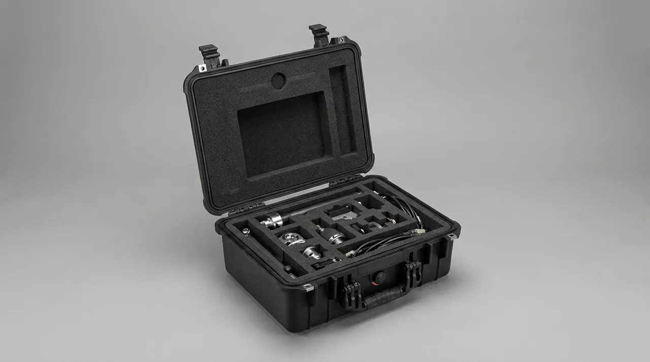
The first decision is vertical or horizontal transport. Columns under 900 mm may lie down, but support spacing must stay under 350 mm and every support must be a V-block, because a cylindrical surface resting on a flat face produces line contact that converts any hard corner into a point load. Columns longer than 900 mm should travel vertically, passing through two locating plates, one at the case floor and one near the lid, with the upper bore lined by a 3 mm rubber sleeve. The column then hangs from above and rests below, so self-weight generates no bending moment at all, and no part of the cylindrical surface is exposed to direct contact.
Hard chrome plating is a hard, brittle film, commonly 20 to 40 microns thick with a surface hardness above HV 800. It resists sliding abrasion well and point loading poorly. A column that has been pressed by a sharp timber corner may show only a shallow mark while cylindricity has already drifted 0.02 mm beyond tolerance, and the machine responds with a stiff, juddering stroke. Keep a clear envelope of at least 15 mm around every column, and forbid timber, steel banding and bolt heads from entering that space.
Linear rail sets need different treatment. Rails and blocks are matched and preloaded at the factory, commonly to Z0 or Z1 grade. If a block slides freely during transport and repeatedly hits its end stop, the raceway and the recirculating end cap take damage. Move each block to the middle of its rail, lock it with a nylon clamp or cable tie, and lay the assembly in a contoured groove with a 5 mm EVA floor and 10 mm of axial clearance at both ends. A rail is a surface-ground precision item, so steel banding and wire rope are never acceptable restraint, because the tension bows the rail permanently in the direction nobody measures.
Contact-Free Packaging for Vacuum Cups, Clamp Plates and Sweep Bars
The end effector is the most fragile assembly on the machine and the easiest to overlook during receiving inspection. Vacuum sealing behaves unforgivingly: once a cup lip is flattened or cut by more than 0.2 mm, vacuum build time lengthens, and at high cycle rates the result is a random failed pick.
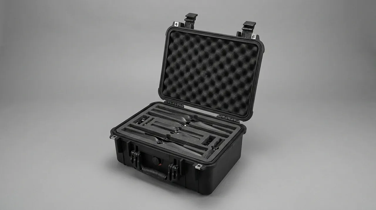
Three rules govern cup packing. First, remove them if the design allows. Cups mount on cup stems through clamps or threads, so removal costs a few minutes and takes the most fragile components out of the load path completely. Place removed cups by lip diameter into EPE or EVA contoured grooves, one layer only, never stacked, and never mix diameters in one groove because a large cup squeezed into a small groove rolls its lip outward.
Second, if removal is impossible, restrain the whole array. Some designs connect the cup array to the vacuum tubing through push-in fittings, and repeated disassembly raises leak risk more than it removes. In that case add a rigid guard of 3 mm PE or aluminium sheet outboard of the array, with at least 25 mm clearance to the cup lips, and fix the guard to the fixture frame rather than pressing it against the cups. The guard exists to intercept external objects, not to clamp the array.
Third, the polyurethane pads, sweep bars and layer pusher plates that travel with the cups are thin-plate items that tolerate pressure poorly and bending very poorly. Pad compound usually runs Shore A 60 to 80 at 5 mm to 15 mm thickness, and after a point load the thickness becomes uneven, which unbalances clamp pressure and scuffs bottles on a glass line. Lay these parts flat over a 10 mm EPE bed with nothing placed on top, and treat sweep bars and pusher plates longer than 800 mm as long parts with support spacing under 400 mm.
Storage conditions matter as much as blocking. Silicone and polyurethane age faster under direct sun and high temperature, and a marine container can exceed 60 degrees Celsius, so place the individual cup and pad boxes low in the crate where temperature is lower, and mark the crate to avoid heat exposure. On arrival, a cup that looks glossy, tacky or visibly discoloured has already aged, and the batch should be sampled for vacuum build time before installation.
Deflection Control for Lift Columns and Long-Stroke Structures
The lift column is the only member on a depalletizer that carries accuracy and load together. The common construction is a rectangular tube outer column with an internal lift carriage driven by chain, rack or ball screw, with a stroke of 2,000 mm to 3,000 mm and a section between 120 mm and 200 mm square.
Failure mode tracks length closely. Below 1,500 mm, two supports suffice. From 1,500 mm to 2,400 mm, three supports are mandatory with the middle one near mid-length. Above 2,400 mm, use four supports with spacing no greater than 800 mm. Every support should be a U-shaped or square saddle matched to the tube section, formed from 30 mm to 40 mm XPE or a 25 mm rubber-plastic composite at Shore A 50, with an R transition at the contact edge and a contact width of at least 70 percent of the section width. The controlling variable is support position, not cushion thickness, because a support sitting over the open middle of a side wall cannot prevent local panel deflection no matter how thick the pad is.
Columns usually arrive with chain tensioners, counterweights or ball screws already installed. Lower the counterweight to its bottom position and secure it with a temporary brace so it cannot hammer the end buffer during road vibration. On a ball screw, move the nut to mid-stroke and lock it, so the exposed screw does not spend weeks sagging under its own weight. When a column lies horizontally and must be stacked, route the stacking load through vertical timber posts down to the case floor rather than through the tube walls.
A more thorough option is to separate the lift carriage from the column and pack the carriage rails and blocks as their own items, shipping the column purely as a structural member. This adds assembly time at site but removes the two most expensive precision components from the compression chain entirely. The support reasoning for a long-stroke linear mechanism appears in the same form in ball screw and rail protection for linear actuator cases, where stroke length and support spacing drive the whole design.
Compartment Fixing for Cam Indexers, Linkages and Chain Drives
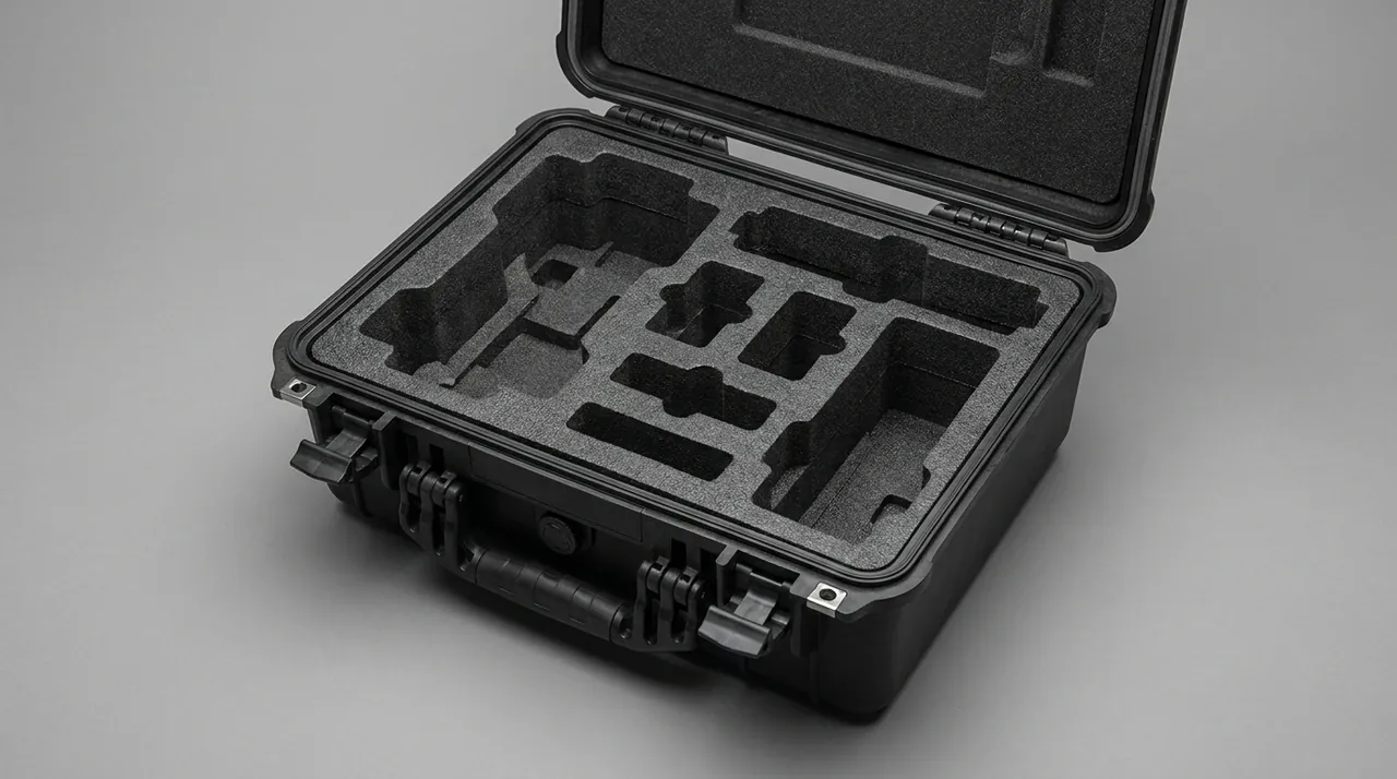
The cam indexer drives the layer pusher and indexing stations and belongs to the group of parts that tolerate shock least. Internally, a cam transmits motion to needle rollers or rollers under preload, and indexing accuracy is often quoted in arc seconds. A shock above design level presses marks into the rollers, which surface as indexing jitter, position drift and periodic noise. Visual inspection on arrival will not find this class of damage.
Three layers of protection apply together. The damping layer is a 20 mm to 25 mm rubber or rubber-plastic pad at Shore A 40 to 50 placed under the entire mounting face, not only under the four corners. The restraint layer uses timber or aluminium stops limiting movement in four directions with gaps held under 3 mm. The orientation layer requires the output flange facing upward or lying horizontally, never with the output shaft pointing down and carrying load. Mark the crate as no-drop and fit a shock indicator label set to a threshold around 5 g, so arrival inspection has an objective record.
Linkages are machined components with rod-end bearings, and they fear bending and joint contamination. Rest them directly on the case floor with a mid-span support, plug both rod-end bores with PE plugs and coat them in grease. Leaning a linkage against a crate wall is a common shortcut that lets self-weight create a bending moment which vibration then amplifies.
Chain drives share one requirement with every other drive item: remove, oil and separate. Take the roller chain off its sprockets, bag it in oil, and store sprockets flat with face-to-face contact separated by dividers. A timing belt must never be folded, only coiled at its natural bend radius or hung, because a fold leaves a permanent crease in the backing. The general treatment of rust prevention, sealing face isolation and hardware joints described in hinge, latch and seal selection for toolboxes transfers directly to these motion pairs.
Isolation of Servo Motors, Gearboxes and Timing Pulleys
Depalletizer axes are normally driven by servo motors with planetary or worm gearboxes. The shared sensitive features are bearings, splines and keyways, and the shared failure cause is axial shock and radial squeeze.
Keep motors and gearboxes assembled and pack them as a unit rather than splitting them to save volume, because field reassembly rarely matches factory coaxiality. Three rules follow. Motors still mounted on the machine should stay in place with a temporary support under the cantilevered end, so motor weight does not sit on the gearbox output bearing for weeks. Motors and gearboxes already removed should stand vertically on a timber base with the flange face down over a 15 mm rubber pad and timber stops on four sides. Any exposed output shaft should be coated with grease, sleeved in PE, and the sleeve wrapped in EPE.
Timing pulleys and gears are judged on tooth faces and locating bores. Wrap tooth faces in expanded PE and place them flat, never stacked. Bore and keyway fits are usually H7 to js6, so any burr raised by contact makes assembly difficult; cap every bore with a plastic plug. Gearbox lubricant can seep from a breather when a unit lies on its side for weeks, so plug the breather before packing and label the crate to remind the site to remove the plug and check oil level on arrival.
Combining motor hardware into the same compartment saves time at both ends. Bag motor mount bolts, washers, keys and coupling inserts by axis number matching the electrical drawing, which cuts site search time and prevents a key being fitted to the wrong slot and forcing a second teardown.
Shock and Static Protection for Photoelectric, Encoder and Light Curtain Hardware
Depalletizers carry many electrical and sensing items that are expensive, numerous and prone to hidden failure. The sensitive group includes photoelectric switches in through-beam and reflective versions, laser distance sensors, incremental and absolute encoders, proximity switches, vacuum pressure switches and safety light curtains. Their common weakness is vibration and static discharge rather than water.
Protection works in three tiers. The static tier requires encoders, sensor boards and servo drive modules to go into shielded antistatic bags immediately after removal, with 5 g to 10 g of desiccant, and then into a compartmented cushioned box. Do not close these bags with ordinary tape, because peeling generates a static charge in the kilovolt range; use an antistatic closure strip. The vibration tier uses 20 mm EPE or 25 mm EVA inside the box, with the box itself held with zero freedom inside the crate and 10 mm to 15 mm of compression left in the vertical direction for absorption. The separation tier keeps safety light curtains, which are long precision assemblies, in individual packs with emitter and receiver separate from each other, never stacked, and never sharing a compartment with metal parts, because the lens window and internal optics deform under the slightest squeeze.
Cleanliness and heat are the two hidden variables. Where the depalletizer serves aseptic filling or pharmaceutical packing, the site controls cleanroom class under ISO 14644, and liner debris during unpacking counts as a foreign-body risk, which restricts liner materials to PE, EVA, XPE and nonwoven fabric while banning sponge and corrugated honeycomb. On heat, the storage ceiling for encoders and light curtains is often 70 degrees Celsius, which a marine container can approach, so place the electrical cases low in the container and away from the roof.
Arrival checks should match these failure modes. Verify shock and tilt indicators, examine antistatic bags for bulging caused by moisture exposure, and spot-check insulation resistance before power-up. When a sensor misbehaves after energizing, the cause is more often a displaced optical axis or a dirty lens than a failed device, and cleaning plus realignment usually restores function without a replacement.
Keeping Air Manifolds, Vacuum Generators and Solenoid Valves Clean
Pneumatic components are the most numerous group on a depalletizer and the easiest to damage quietly. Vacuum generators, valve manifolds, solenoid valves, air plates and push-in fittings form one highly integrated air circuit, and a single broken fitting or sticky spool destroys the machine's ability to grip anything.
Contamination is the primary enemy, and it arrives from two directions: debris generated during packing and dust or moisture from the site air supply. On the packing side, cap every port before the crate closes, close unused outlets with dust caps or blanking plates, and protect manual override buttons so they cannot be pressed accidentally in transit and hold a spool in the shifted position for weeks. Push-in fittings are the weakest single point. A tube must not be pulled sideways at the fitting, so coil tube bundles separately and tie only the bundle, never the fitting. When an air plate and manifold travel as one assembly, fix it in its own compartment over 20 mm EPE and keep weight off the top.
Air quality guidance belongs in the shipping documents. Pneumatic systems react badly to water and particles, so the site air supply should be specified against the solid particle, water and oil classes of ISO 8573-1, with a common industrial target being class 4 for particles, 4 for water and 4 for oil, supported by a filter regulator and dryer ahead of the machine inlet. Skip this and a newly installed depalletizer will show sticky spools within two months, with the blame usually landing on the crate or the product. The crate-level sealing and moisture control techniques used for pneumatic hardware follow the same reasoning as waterproof case construction at IP rated levels, where the objective is controlling the path by which water vapour enters.
Torsion Control for Grab Frames and Aluminium Profile Structures
The grab frame is the skeleton of the fixture, built from aluminium profiles or welded thin-wall tube, and frequently larger than 1,200 mm by 1,000 mm. It is a large, flat, thin-walled structure. Compression is not its problem; torsion is. If a frame rides on only two supports placed toward one side, self-weight produces diagonal twist, and on site the cup array is no longer coplanar, clamp plates open out of sync, and the first contact point lands early.
The engineering answer is three-point support plus diagonal verification. Locate supports near three of the four corners on structural nodes of the profile. Place nothing on top of the frame, because the local load capacity of an aluminium profile is far below that of a steel structure. If stacking is unavoidable, add four rigid posts so the upper load reaches the base structure directly. Record both diagonal measurements before packing, typically within 1 mm to 2 mm of each other on a healthy frame, and remeasure on arrival, because the change in diagonal difference is direct evidence of twist.
Frame joints need their own attention. Brackets, T-nuts and socket screws work loose under vibration, so recheck every joint to the specified torque before packing and mark each with a witness line; any offset witness line on arrival tells you the joint has moved. Rubber bumper strips and cushion blocks on the frame are compound items that dislike oil and heat, so keep them out of compartments shared with unsealed gearboxes or oil-filled components.
Liner and Cushion Structure Selection Matrix
Liner selection follows four variables: component mass, sensitive face, contact geometry and transport mode. Price is not one of them. On a single depalletizer, a cam indexer needs damping, a cup needs contour location, a guide column needs clearance, and a frame needs torsion control, and no single material satisfies all four.
| Component | Mass Range | Critical Face | Liner Structure | Restraint Method | Recommended Material |
|---|---|---|---|---|---|
| --- | --- | --- | --- | --- | --- |
| Guide column, vertical | 5 to 25 kg | Plated cylinder | Top and bottom locating plates with rubber sleeves | Bore fit, radial clearance under 0.5 mm | 3 mm rubber sleeve plus 15 mm clearance |
| Linear rail set | 3 to 20 kg | Raceway and block | Full-length contoured groove | Block locked at mid-rail, axial clearance | 5 mm EVA groove floor |
| Vacuum cup array | 2 to 15 kg | Lip sealing face | Single-layer contoured grooves | Individual pockets, no stacking | 20 mm EPE or 25 mm EVA |
| Lift column | 40 to 200 kg | Tube wall and rail face | Multiple saddle supports | Support spacing under 800 mm | 30 to 40 mm XPE at Shore A 50 |
| Cam indexer | 20 to 90 kg | Output flange and bearings | Suspended cradle plus damping pad | Timber stops, gaps under 3 mm | 20 to 25 mm rubber at Shore A 45 |
| Grab frame | 30 to 120 kg | Plane and diagonals | Three-point support, open top | Circumferential timber stops | 25 mm rubber-plastic composite |
| Electrical and sensor box | 1 to 10 kg | Circuit and optics | Compartmented cushioned box | Zero freedom, compressed | 20 mm EPE plus antistatic bag |
One trap deserves a warning: density and hardness are not proxies for safety. EVA at 25 kg/m3 and at 45 kg/m3 behave very differently under static load. The lower density suits a conforming layer, the higher suits a load-bearing block, and using a dense material as a conforming layer concentrates pressure on individual high points. A practical screening procedure is to place the actual component on candidate pads, leave it for 48 hours, measure compression and recovery, then extrapolate creep against an equivalent 30-day stacking pressure before fixing the grade. JUNZHIJIA splits liners into load-bearing, conforming and clearance zones based on the component centre-of-gravity drawing and lifting points supplied by the buyer, selects material separately for each zone, and ships a liner material list so receiving inspection can verify by comparison. Broader material trade-offs are covered in the protective case foam material comparison.
Case Markings, Shipping Documentation and Arrival Checks
Case markings on this equipment must answer three dock questions: what is inside, may it be stacked, and how is it lifted. Following the general requirements of GB/T 191 and GB/T 13384, include this side up, keep dry, do not stack, centre of gravity, lifting points, and case number with total count. For class 1 items such as cam indexers, light curtains and cup arrays, repeat do-not-stack and do-not-tilt on all four faces rather than one.
Ship five document sets in a waterproof bag fixed to a visible position: a packing list with case numbers and lifting points, a packaging specification covering liner materials, support positions, stacking and tilt limits, pneumatic and electrical disassembly notes, inspection data for key items such as indexer accuracy, column cylindricity and cup vacuum build time, and a non-conformance and claim evidence procedure. Placing documents at the bottom of a compartment box defeats their purpose.
Arrival checks run through condition, dimension and function. Condition covers the crate skin and labels. Dimension covers frame diagonals, column straightness and free-state column deflection. Function covers a low-speed trial run after assembly, watching for juddering travel, fixture tilt and vacuum build time outside the expected band. A tabulated inspection record moves disputes earlier and turns the packaging specification into an executable document. Where the buyer requires a formal supplier file set, JUNZHIJIA can supply packaging design notes and an inspection template for the audit archive, and the criteria for choosing a supplier able to produce such documentation are set out in how to choose a protective case OEM factory.
Container Loading and Split-Shipment Coordination
When a depalletizer ships split, coordination between packing units affects the outcome more than the quality of any single crate. The stowage plan must be settled during packaging design, not after the crates are built.
Four stowage rules cover most cases. Put heavy crates low, long crates along the sides, and no-stack crates near the doors, so forklift and crane work rarely crosses them. Brace crate against crate with cross-set timber or longitudinal battens to create one stiff body and stop a row from colliding in heavy roll. Place long crates lengthwise with supports landing over container floor cross members rather than straddling a floor joint. Keep electrical and pneumatic cases away from the doors and out of the path of water ingress, and put structural items at the doorway. For moisture, install a pressure equalization valve on reasonably sealed cases with a desiccant load sized from internal volume.
Test programme selection should follow the distribution cycle. Domestic road and rail shipments align with the GB/T 4857 series for vibration and drop conditions. Export orders may specify an ASTM D4169 distribution cycle or an ISTA 3E test on the complete unit load. These standards provide methods and environmental severities only; they do not constitute a certification, and no military or industry qualification should be claimed on the basis of passing them. Final intensity is agreed between buyer and supplier against a defined assurance level. Application of these methods is discussed further in distribution cycle testing under ASTM D4169.
Common Questions and Answers
Q: Must the vacuum cups be removed and packed separately?
A: Removal is recommended unless the cup array is permanently linked to the vacuum tubing in a way that makes disassembly riskier than transport. The value of removal is that it takes the lip sealing face out of the compression and squeeze environment entirely. A lip flattened by more than 0.2 mm lengthens vacuum build time, and at high depalletizing rates that shows up as intermittent failed picks, damage that visual inspection on arrival will almost never detect. When cups are removed, place them by lip diameter into EPE or EVA contoured grooves in a single layer, never mixed by diameter, because a large cup forced into a small groove rolls its lip outward; wrap surfaces in nonwoven fabric first and shape them with PE film. When the array stays assembled, fix a rigid guard to the fixture frame with at least 25 mm clearance to the lips. Either way, mark the case to avoid heat, since silicone and polyurethane age quickly above 60 degrees Celsius.
Q: Vertical packing for guide columns costs more. Is horizontal packing acceptable?
A: Yes, provided support count and support form change accordingly. The decision variable is the length-to-diameter ratio. Below 15, two supports near the ends are adequate. Between 15 and 30, three supports are required with spacing under 350 mm. Above 30, vertical packing is the better choice. The dominant risk in horizontal packing comes from contact geometry, because a cylinder on a flat face contacts along a line that vibration converts into a point load as soon as any corner touches it. Hard chrome plating, although above HV 800, resists point loading poorly, and a column that has been pressed may show only a shallow mark while cylindricity has already exceeded tolerance by 0.02 mm. Horizontal packing therefore requires V-blocks with a 90 to 120 degree included angle, a 3 mm rubber lining, at least 15 mm of clearance around the cylinder, and a ban on steel banding or wire rope directly against the plated surface. When budget allows, vertical packing through top and bottom locating plates carries the lowest combined risk and simplifies crane handling at site.
Q: How can damage to a cam indexer be detected early after arrival?
A: Appearance and feel will not reveal it, so measurement and trial running are both required. Measure output flange face runout and radial runout with a dial indicator while the unit is free, compare against the factory record, and treat a deviation beyond 1.5 times the factory value as a suspicion trigger. Trial running means operating slowly and listening for periodic clicking, then watching for rebound as each index position is reached. A more proactive measure is a shock indicator label inside the crate set to roughly 5 g, combined with a record of every transshipment point, so that a discoloured label triggers disassembly even when the exterior looks perfect. Prevention requires the whole base of the indexer to sit on a 20 mm to 25 mm rubber pad at about Shore A 45, four-way timber stops with gaps under 3 mm, the output flange facing up or lying horizontally, and a strict ban on sharing a compartment with heavy parts or carrying any load on top.
Q: Can a twisted aluminium grab frame be straightened on site?
A: Straightening on site is not recommended in principle, because once an aluminium profile yields, the correction introduces new internal stress and neither weld positions nor joint holes return to their original state. The direct evidence of twist is diagonal difference. Record both diagonal lengths before packing, typically within 1 mm to 2 mm on a healthy frame, then remeasure on arrival; a change beyond 2 mm is strong confirmation that twist occurred. The usual cause is transport on two supports placed toward one side, letting self-weight generate torque. Handle it by photographing the condition, documenting liner imprints and support positions, and confirming a replacement or repair route with the supplier. Prevention means three-point support on structural nodes, nothing placed on top of the frame, and four rigid posts in the middle when stacking is unavoidable, so the upper load reaches the base structure rather than the profile surface. Where the twist is minor and the buyer accepts a temporary repair, correct it only under written supplier instruction with the fixture unloaded, and verify cup array coplanarity again before production starts.
Q: When pneumatic components stick soon after arrival, is it a packing fault or the site air supply?
A: Both are possible, and data separates them. Packing-side risks include unsealed ports letting dust enter, manual override buttons accidentally pressed so a spool stays shifted, and push-in fittings deformed by sideways tube tension; all three can be assessed at unpacking by checking that dust caps are present, button guards are seated and fittings show no deformation. Supply-side risk is water and particles, and a site that has not specified the solid particle, water and oil classes of ISO 8573-1, and has not installed filtration, regulation and drying ahead of the machine inlet, will commonly see sticky spools within two to three months of commissioning. State the air quality requirement in the shipping documents, add a line to the receiving checklist that verifies the air preparation unit, and require lines to be blown through before first energization. That combination draws a clear responsibility boundary in writing before the first complaint arrives. Keep the exchange documented, because a spool that sticks twice in the same valve body usually points to air quality rather than a packing defect.
Q: How should stacking be limited for depalletizer component cases?
A: Work backward from the allowable compressive load of the most sensitive item inside, not from the strength of the crate. A timber case usually tolerates two or three layers, but class 1 items such as guide columns, linear rails, cup arrays, cam indexers and light curtains effectively tolerate none, so those cases must be marked do-not-stack on all four faces and positioned in the upper layer or near the doors. Stacking is limited to structural and frame cases, and even there the stacking load must pass through internal tooling posts or vertical timber rather than through the component body. For practical stowage, build a loading table showing total piece count, individual gross weight, allowable stacking layers and lifting points, and circulate it with customs and freight documents so that a transshipment port does not restack from the crate marks alone and bury a no-stack case at the bottom of the pile. Treat any case holding a class 1 item as non-stackable by default, not by exception.
Q: What extra liner requirements apply to depalletizers serving food and pharmaceutical lines?
A: The core requirements are controlled shedding and no chemical migration, verified by a white-paper wipe. Three rules follow. First, exclude high-shedding materials including sponge, corrugated honeycomb and recycled-content foam. Second, materials touching cups, pads and rail faces must be plasticizer free, which limits them to PE, EPE, EVA, XPE, nonwoven fabric and aluminium-laminate film. Third, liner material should be traceable to batch and named with its density in the packaging specification. Where the site classifies cleanliness under ISO 14644, treat the liner as a contamination source and unpack in a designated area outside the clean zone, removing layers in sequence rather than carrying outer packaging inward. GB 14881 and food GMP rules aim at keeping foreign bodies out of product, and in the logistics chain the effective controls are low shedding, traceable material and a controlled opening sequence, which deliver more real protection than simply increasing cushion thickness. Keep the material list inside the case rather than in a separate envelope that can go missing before arrival.
Q: How should component cases be graded across transport modes?
A: Grade by handling count and lifting complexity rather than distance. A direct full-container sea shipment has the fewest handlings and can be designed around a 0.8 m to 1.0 m drop level, with engineering effort focused on moisture control and creep under stacking for more than thirty days. Rail and less-than-truckload road freight involve repeated lifting and transshipment, so the priorities become wear resistance at lifting points, frame stiffness and secondary internal restraint. Air freight and express involve the most handlings, so specify a 1.2 m drop level and fit shock indicator labels. The three grades differ in cushion thickness, frame specification and restraint strength, and applying the top grade to every order wastes volume and freight. Publish the three grades for selection at quotation, and note the chosen grade on the packing list so a discoloured label can be judged against a known design envelope.
Conclusion and Further Reading
Two problems dominate depalletizer crating. Precision items suffer invisible damage, where a column, rail or indexer looks perfect and is already out of tolerance. Frames and long columns deform because of support position, not cushion thickness. Pull class 1 items out of the compression chain, calculate long-part support spacing from deflection, and isolate electrical and pneumatic hardware.
Further Reading