

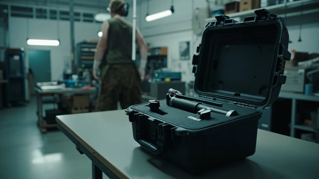
Transit damage to scissor lifts usually happens before the machine is connected to power. A scissor arm takes a slight bend in transit, so after assembly the platform drifts and rattles as it rises. A pin bore fit surface is burred, so the pin cannot rotate freely and the mechanism binds. A hydraulic cylinder piston rod is scored and starts weeping weeks later. A platform roller is dented, so the lift skips and judders. A limit switch or height sensor is broken, so the safety protection fails. These faults are hard to catch at factory inspection and surface only after commissioning, when the only remedies are teardown rework or downtime replacement. The conclusion is clear: a scissor arm is a slender structural member highly sensitive to straightness; a pin bore is a fit surface that tolerates no burr or deformation; a hydraulic cylinder is a precision actuator whose rod integrity governs seal life; platform guards and rollers are shape and rolling accuracy items; and electrical parts are moisture- and ESD-sensitive assemblies. Their outer packaging must be a dedicated parts case with layered location, anti-deformation support, cleanliness control, and moisture sealing - not a crate stuffed with filler, not stretch wrap, and not bare parts tied together.
Four characteristics set scissor lift components apart. In the trade this packaging category is generally called a scissor lift case, subdivided by component into scissor parts cases and lift component cases, all brought under one numbering and traceability system for scissor equipment cases and aerial work platform cases. The first is structural deformation sensitivity. A scissor arm is a slender bent-plate or section-steel member with limited bending stiffness, and its straightness governs the synchronisation and smoothness of the scissor mechanism as it raises. Once a plastic bend occurs, on-site correction is very limited and leaves residual stress. The second is the precision nature of pin fits. The whole motion of a scissor mechanism depends on relative rotation between pins and bores, and the clearance between pin and bore is set at the factory. Burrs and ovalisation from impact directly cause binding and accelerated wear. The third is hydraulic cleanliness and rod integrity. Scissor lift cylinders are long-stroke, high-thrust designs, and the hard-chrome piston rod is a sliding fit whose scores become starting points for leakage and seal wear, while particulate contamination causes valve spool sticking. The fourth is their aerial work platform role. Guards, decks, limit switches, and sensors relate directly to operator safety, so transit damage to them is a safety-relevant risk.
This article is written for scissor lift manufacturers, aerial work platform builders, equipment rental companies, and project buyers. Section by section it sets out how scissor and hydraulic components are graded for protection, how inserts and supports are designed, which standards the scheme is validated against and what acceptance looks like at the site; the engineering capability behind custom inserts and OEM/ODM supply is described along the way.
Table of Contents
- 1. Why Scissor Lift Components Need a Dedicated Parts Case
- 2. Scissor Lift Component List and Protection Grading
- 3. Failure Modes: Arm Bending, Pin Bore Deformation, Rod Scoring and Roller Damage
- 4. Scissor Structure Geometry and Packing Strategy
- 5. Scissor Lift Case Structure and Material Selection
- 6. Insert Design: Layered Stacking, Divided Pin Cavities and Bore Protection
- 7. Protecting Hydraulic Cylinders and Power Units
- 8. Platform Guards, Rollers and Slider Components
- 9. Protecting Electrical and Control System Parts
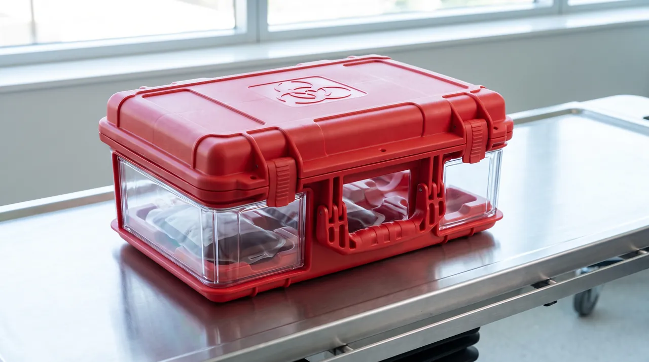
- 10. Choosing the Sealing Class: IEC 60529 and GB/T 4208 Applied to Scissor Cases
- 11. Vibration Validation for Scissor Arms and Cylinders: GB/T 4857 and ISTA
- 12. Stacking, Lifting and Centre-of-Gravity Control for Scissor Cases
- 13. Labelling, Traceability and Scissor Lift Site Installation Management
- 14. OEM/ODM Customization: Acceptance and Maintenance for Scissor Cases
- Frequently Asked Questions
- Conclusion & Related Reading
1. Why Scissor Lift Components Need a Dedicated Parts Case
A scissor lift is a classic combination of slender structure, hydraulic actuation, and aerial work safety. Its core components are machined to demanding accuracy, and much of that accuracy is squandered at the packaging step.
For a scissor arm, straightness is the function. The kinematics of a scissor mechanism depend on two sets of arms rotating synchronously about a centre pin. Straightness deviation in an arm translates directly into horizontal drift and sway of the platform as it rises. If the two sides differ in straightness, the platform tends to tilt, in severe cases triggering tilt protection or impairing the work. Scissor arms are usually bent plate, rectangular tube, or welded section-steel structures with a high length-to-diameter ratio and limited bending stiffness, so an unsupported mid-span, end loading, or a lateral strike in transit readily produces a slight plastic bend.
For a pin bore, the fit surface is the precision. All rotation in the mechanism depends on pin-to-bore fit. Bore internal cylindrical accuracy and surface roughness are completed at the factory, and the clearance between pin and bore sets both motion accuracy and play. Burrs, ovalisation, or a raised bore edge make the pin unable to rotate freely and cause binding, and forcing assembly damages the fit surfaces further.
For a hydraulic cylinder, surface integrity is life. Scissor lift cylinders are often long-stroke, high-thrust double-acting designs with a hard-chrome piston rod. A scored plating layer breaks seal lip contact and becomes a leak path, while a dent creates a high spot that accelerates seal wear. Long-stroke cylinders have a high length-to-diameter ratio and are also prone to bending under transport vibration.
Hydraulic contamination is a concealed failure source. Particles circulating with the oil into the clearance between spool and bore make the spool sluggish or seize, showing as uneven lifting, incomplete movement, or loss of self-locking. Contamination is often introduced during packaging and transport: crate wood dust, foam crumbs, and floor grit entering through uncapped oil ports surface weeks to months later.
The integrity of aerial work safety items is non-negotiable. Guards, decks, fall-arrest devices, limit switches, and height sensors relate directly to operator safety. A deformed guard leaves insufficient protection height, and a broken limit switch disables hoisting limit protection. Such damage cannot be judged minor on site and must be treated as non-conforming.
Key reminder: scissor lift component damage is cheap to prevent, expensive to reverse, and relevant to aerial work safety. The on-site cost of a single plastic bend in a scissor arm, covering correction, re-inspection, and loss of rental availability, far exceeds the packaging investment for the whole batch.
For scissor lift manufacturers and aerial work platform builders, the parts case also acts as standardised tooling. Building a standard case series by model platform height and scissor arm size significantly reduces storage and circulation cost; the method for judging how many trips a case is good for is set out in protective case service life and reuse years.
2. Scissor Lift Component List and Protection Grading
A scissor lift spreads its risk across five very different part families, so assign a grade to each before anything goes into the case.
| Part family | Construction | What fails first | Grading and protection |
|---|---|---|---|
| --- | --- | --- | --- |
| Scissor arm (bent or section) | Bent plate, rectangular tube, section steel | Straightness, pin bores, flatness | Layered stacking + multi-point support + bore sleeves |
| Centre pin and connecting pins | Quenched and tempered alloy steel | Outer fit surface, threads, oil ways | Isolated cavity + outer sleeve + thread sleeve |
| Pin bushing and self-lubricating liner | Bronze-based or composite | Bore, end face | Flat compartments + sleeves |
| Hydraulic cylinder | Barrel plus chrome-plated rod | Rod plating, barrel roundness, pin bores | Contoured slot + full rod coverage |
| Power unit (pump station) | Reservoir, pump, motor, valves | Pump shaft, oil ports, insulation | Isolated cavity + damping pad + barrier bag |
| Hydraulic valve block and control valve | Cast iron or aluminium body | Sealing faces, port threads | Isolated cavity + port plugs + anti-rust paper |
| Hydraulic hose and tube | Rubber, steel | Bend radius, fitting threads | Large-radius coiling + fitting sleeves |
| Platform guardrail | Bent tube or section | Straightness, welds, coating | Upright divided cavity + edge guards |
| Deck and platform surface | Tread plate or grating | Flatness, anti-slip teeth | Flat layering + surface film |
| Roller and slider | Alloy steel, nylon, PU | Rolling surface, mounting bore | Dedicated slot + protective film |
| Fall-arrest device and safety lock | Precision mechanism | Pawls, springs, fit surfaces | Isolated damped cavity + pre-compression |
| Limit switch and height sensor | Electronic, electromechanical | Contacts, code disc, cable | Small-parts box + ESD packaging |
| Control box and inverter | Sheet-metal box, PCB | Moisture, dust, ESD | Barrier bag + ESD bag + damped support |
| Access ladder and handrail | Bent tube | Straightness, coating | Upright divided cavity + edge guards |
| Fasteners and pin circlips | Alloy steel | Threads, elasticity | Compartment box + anti-rust paper |
| Seals and oil seals | Rubber, PU | Deformation, ageing, oil | Flat compartments + light-blocking bag |
The table shows that scissor arm straightness and pin-to-bore fit accuracy are the two physical protection themes, hydraulic rod integrity and electrical moisture and ESD control form a third, and the integrity of safety items such as guards, fall-arrest devices, and limit devices is a fourth, non-negotiable theme.
3. Failure Modes: Arm Bending, Pin Bore Deformation, Rod Scoring and Roller Damage
Plastic bending and twisting of scissor arms. Scissor arms have a high length-to-diameter ratio and limited bending stiffness. Shipped bare with an unsupported mid-span, loaded at the ends, or struck laterally, an arm acquires a plastic bend; stacked with misplaced supports, it can twist as well. Once bent, the kinematic relationship of the mechanism is broken, showing as platform drift, poor synchronisation, and local binding.
Damage to arm flanks and welds. Arm flanks often serve as guide or stop faces, and impact damage leaves local high spots that interfere in operation. Damage near a weld becomes a crack initiation site.
Pin bore burrs, ovalisation and raised bore edges. A pin bore is a fit surface. Impact produces burrs and raised bore edges, so the pin cannot rotate freely, and forcing assembly scores the pin outer surface and liner bore. A raised bore edge also changes the effective fit length.
Damage to pin and liner fit surfaces. A pin's outer fit surface and a liner bore are precision fits. Scores and dents from impact create early wear and increased clearance, showing as greater mechanism play and abnormal noise.
Piston rod plating scores and dents. Hard chrome is hard but limited in toughness. Contact with section-steel edges, pins, or the case wall produces scores, dents, and even spalling, breaking seal lip contact and becoming a leak path. Long-stroke cylinders also bend under vibration, causing creeping and uneven wear.
Barrel bore damage and ovalisation. The bore is a machined surface. Foreign matter or an end impact scores it, and stacking pressure or a drop impact ovalises the section so the piston seal cannot seat evenly.
Roller and slider running surface damage. Roller running surfaces and slider fit faces are accuracy surfaces. Impact causes runout and noise, and in severe cases mechanism binding.
Guardrail and deck deformation. Guardrails are usually bent tube with limited bending stiffness, and lateral pressure readily produces a plastic bend that leaves insufficient protection height. Decks are large with limited stiffness, and stacking pressure pushes flatness out of tolerance.
Hydraulic particulate contamination and valve spool sticking. Particles entering the clearance between spool and bore make the spool sluggish or seize, showing as uneven lifting, incomplete movement, or loss of self-locking. Such failures appear late and are hard to trace.
Electrical moisture ingress and insulation loss. Contactors, relays, and inverters in the control box are moisture sensitive, so exposure lowers insulation resistance and in severe cases trips the supply on energising or corrodes the control board. A broken limit switch or height sensor directly disables safety protection.
4. Scissor Structure Geometry and Packing Strategy
The scissor arm is the most geometrically distinctive component in a scissor lift, so packing strategy must be designed around its geometry.
Three geometric characteristics of a scissor arm. First, a high length-to-diameter ratio: arms are typically one to three metres long with a relatively small section depth, so bending stiffness is limited and the natural frequency falls inside the main energy band of road transport vibration. Second, a plate or tube structure with bores: bores at both ends and at the centre set the kinematic relationship through their pitch accuracy, and bore edges are among the most vulnerable features. Third, symmetric paired use: a scissor mechanism uses arms in pairs, and two arms in the same set must match in straightness, or mixing differently conditioned items produces synchronisation differences after assembly.
Grading packing by component size.
| Component class | Typical size | Packing strategy | Key risk |
|---|---|---|---|
| --- | --- | --- | --- |
| Small scissor arm | Under 1 m, under 25 kg each | Layered stacking in contoured slots, several per case | Mutual impact, bore damage |
| Medium scissor arm | 1-2 m, 25-80 kg each | Layered stacking + multi-point support | Bending, twisting |
| Large scissor arm | Over 2 m, over 80 kg each | Upright or layered + lifting points + mid-span support | Bending resonance, lifting deformation |
| Platform frame and guardrail | Large area, low stiffness | Upright divided cavity + edge guards | Lateral bending, coating damage |
| Hydraulic cylinder and power unit | Long stroke, high thrust | Contoured slot + full rod coverage + isolated cavity | Rod scoring, port contamination |
| Pins and bushings | Small, precision | Compartment box + isolated cavity | Fit surface scores, loss |
| Electrical and sensor parts | Electronics | Barrier bag + ESD bag + damped cavity | Moisture, ESD, impact |
Empirical rules for support point layout. When supporting arms in layers, space supports within one third of arm length, and for arms longer than about 2,000 mm use three or more support points. Middle supports should use low-stiffness elastic material to combine restraint with cushioning. Support points must avoid pin bore positions so no stress concentration forms at a bore edge.
Paired management. Arms belonging to the same scissor mechanism should go into the same case, placed adjacent, with the pairing marked inside. This prevents mixing items from different batches or conditions on site and markedly reduces synchronisation adjustment after assembly.
Independent bore protection. Every pin bore should be sleeved with a plastic plug or soft tube so the bore edge cannot be struck into a raised lip. Pins and bushings should have their own cavities so they cannot strike the arms.
5. Scissor Lift Case Structure and Material Selection
A scissor lift parts case has to satisfy three demands at once - slender parts, heavy parts, and aerial work safety parts - so selection balances carrying capacity, stiffness, sealing and weight, usually in that order of priority.
| Case format | Shell material | Working load per item | Why it is chosen | Where it fits on a scissor lift |
|---|---|---|---|---|
| --- | --- | --- | --- | --- |
| Small injection-moulded case | PP, PE | Low to medium (under 60 kg) | Light, tight sealing, nests when empty | Height and tilt sensors, limit switches, pins and bushings |
| Standard rotomoulded case | PE (LLDPE) | Medium to high (around 200 kg) | Takes impact, available in long sizes | Scissor arms, hydraulic cylinders, power units |
| Blow-moulded case | HDPE | Medium (under 100 kg) | Cost-effective with good stiffness | General hardware, control boxes |
| Composite case | FRP or carbon composite | High | High strength-to-weight, dimensionally stable | Large arms, export projects |
| Long or board case | Composite or metal reinforced | High | Suits long slender parts and mid-span supports | Long arms, platform guardrails |
| Base pallet case | Shell plus integrated pallet | Very high | Forklift handling and stacking made simple | A complete scissor mechanism shipped in parts |
Three material selection criteria. First, impact resistance: rotomoulded PE retains good toughness at low temperature and suits heavy loads and outdoor routes, while PP is stiffer but sensitive to low-temperature impact, so cold climate projects must consider the brittle temperature. Second, seal compatibility: gasket material, whether EPDM, silicone, or neoprene, must match the temperature, ozone, and oil exposure of the route. Third, flame retardancy and static: cases containing control boxes and PCBs should have material assessed against UL94 flammability classifications with anti-static inserts selected accordingly.
Three structural requirements for long slender-part cases. First, stiffness design for long cases: a long case supported only at its ends deflects at mid-span, so add ribs or use a sandwich structure so the case itself does not become a vibration amplifier. Second, a clear load path: arms and cylinders must be carried by the case floor and structural members, with the insert providing location and cushioning only. Third, matched hardware: latch, hinge, and handle capacity must match total case weight, and long cases should have more latches to distribute clamping force evenly and prevent local seal failure. Latch selection and distribution are covered in case lock customization options.
Equipment case selection thinking. Scissor lift components combine precision equipment parts with heavy structural parts, so case selection can draw on general equipment case thinking; see instrument case selection guide.
6. Insert Design: Layered Stacking, Divided Pin Cavities and Bore Protection
The insert is the functional core of a parts case. For scissor lift components it must solve layered location, anti-deformation support, isolation, and cleanliness at once.
Scissor arms: layered stacking, multi-point support, bore sleeves. Stack arms horizontally in layers, separating layers with dividers so they never touch directly. Each layer's insert slot should conform to the arm section, and support points must avoid pin bores. Sleeve every pin bore with a plastic plug or soft tube to prevent a raised bore edge. For arms longer than about 2,000 mm, add an elastic mid-span support.
Pins and bushings: isolated cavities and outer sleeves. A pin's outer fit surface is a precision surface, so use an isolated cavity with an outer sleeve, in soft tube or flocked fabric, and sleeve the thread. Store bushings flat in compartments with soft pads at the end faces so they cannot strike each other.
Hydraulic cylinders: contoured slots and full rod coverage. Lay the cylinder horizontally in a slot machined to more than a half circle, so the barrel is carried over an area rather than along a line and contact stress stays low. The exposed rod is the feature that decides seal life, so sleeve it end to end with a split cover whose bore is soft - low-density EVA or flocked fabric - leaving no length of plating able to touch steel. Each end clevis drops into its own slot, and a plug pushed into every pin bore keeps foreign matter from getting a start.
Power units: isolated cavities, damped bases, moisture control. Treat the unit as one assembly in its own cavity, line the cavity floor with a damping pad, and fit locating blocks around the perimeter to limit horizontal travel. Cap all oil ports, and where the unit includes electrical parts, add a desiccant pocket above or beside the cavity plus a barrier bag and humidity indicator card.
Platform guardrails and decks: upright divided cavities and surface film. Store guardrails upright with locating slots on both sides and edge guards at the corners so they cannot bend laterally. Store decks flat in layers with a protective film so anti-slip teeth are not crushed, and control the number of layers to avoid flatness deviation.
Rollers and sliders: dedicated slots and film. Roller running surfaces and slider fit faces should be stored in dedicated slots with film, away from hard components.
Insert machining and tolerance control. CNC routing suits complex contoured slots and small to medium batches; die-cut EVA suits regular shapes and large batches; thermoforming suits curved conformal fits; combined approaches, such as an EVA base with polyethylene foam fill and a flocked top layer, suit high-value items needing layered protection. One case often has to serve several part numbers at once, and a divider set that lifts out and re-seats gives that flexibility without paying for a second mould; see case removable divider system design. Detailed insert design and tolerance control are covered in custom foam insert design guide.
JUNZHJIA is the brand of Kexin New Materials (Guangdong) Co., Ltd. For scissor lifts the insert is drawn around arm length and section, pin diameters, cylinder bore and stroke, and the outline and centre of gravity of the power unit; a 3D insert concept is issued before any physical sampling.

7. Protecting Hydraulic Cylinders and Power Units
Hydraulic parts are the power core of a scissor lift, and their protection priorities differ completely from structural parts.
Rod surface protection comes first. The piston rod plating is the only permanently exposed sliding fit surface in the whole hydraulic system. Three points matter. Full coverage: the sleeve must cover the entire rod with no exposed length. Soft contact: the sleeve inner surface must be a soft material free of plasticizer that could migrate. No unsupported span: long-stroke cylinders need multi-point soft support with spacing within one third of cylinder length, so the rod does not rub repeatedly against the sleeve under transport vibration.
Barrel and port protection. Fit an end face protective cap on the barrel bore to keep out foreign matter and moisture. Cap every oil port and fitting, which is the most important single measure against contamination and leakage.
The compound sensitivity of power units. A power unit contains a reservoir, pump, motor, and valve assembly at once, and must handle mechanical shock, moisture, corrosion, and ESD together. Packing should provide an isolated cavity, a damping pad on the cavity floor, locating blocks around the perimeter, capped oil ports, a capped motor terminal chamber, and anti-static shielding bags plus barrier bags for PCB-containing parts.
Protecting valve block sealing faces. Valve blocks have complex internal passages and many sealing faces, and impact causes leakage under high pressure. Use isolated cavities with port plugs, and do not put several valve blocks in one cavity.
Hoses and bent tubes. Roll a hose coil to a bend radius of at least six to eight outer diameters, then tie the coil so it cannot open in transit. Where a rigid tube is bent, cradle the bend in a contoured pocket or a divided slot, and put a sleeve over every thread left exposed.
What cleanliness looks like in practice. ISO 4406 rates oil contamination with a three-number code covering particles above 4, above 6 and above 14 micrometres per unit volume; the smaller the numbers, the cleaner the oil, and on a scissor lift that figure decides how long the valve spools and the pump last. Packaging is one of the places where the count gets worse, through insert debris, dust off the shop floor, and whatever the case carried last time. Four controls cover it: clear machining debris out of the insert and prefer closed-cell grades such as EVA and IXPE that do not shed; keep the packing bay physically separate from the machining bay; cap every oil port and valve port and film the critical fit surfaces; and sweep out and wipe the empty case on every return.
8. Platform Guards, Rollers and Slider Components
Platform-side components relate directly to aerial work safety, so protection requirements are stricter than for general structural parts.
Guardrails and handrails: bending and coating together. Guardrails are usually bent tube with limited bending stiffness. Lateral pressure or stacking compression in transit produces a plastic bend and insufficient protection height. Store them upright, restrained by locating slots, supported symmetrically on both sides, with edge guards protecting the coating. Coating damage does not reduce strength but becomes a corrosion initiation point and affects appearance and service life.
Decks and platform surfaces: flatness and anti-slip teeth. Decks are large with limited stiffness, and stacking pressure pushes flatness out of tolerance, causing movement in service. Anti-slip teeth, whether tread pattern or punched and flanged, bend over when crushed and lose grip. Store decks flat in layers with soft dividers between them, limit the number of layers, and mark the permitted layer count on the case.
Rollers and sliders: running surface accuracy. Roller running surfaces and slider fit faces are accuracy surfaces. Impact causes runout and noise, and in severe cases mechanism binding. Store them in dedicated slots with film, away from hard components.
Fall-arrest devices and safety locks: pre-compression fixing. Fall-arrest devices and safety locks contain pawls, springs, and fit surfaces. Impact deforms the pawls or permanently sets the springs, directly impairing the fall-arrest function. Use an isolated damped cavity, fix springs in a pre-compressed state, and manage them as safety items.
Access ladders and accessories: dedicated cavities. Ladders, handrails, and accessories are usually thin-walled tube and should have dedicated cavities with edge guards, away from heavy items.

9. Protecting Electrical and Control System Parts
Scissor lift electrical and control systems include the control box, inverter, contactors, limit switches, height sensors, tilt sensors, operator panels, and cables, all sensitive to moisture, ESD, and shock.
Moisture control for control boxes and inverters. Contactors, relays, and terminals are moisture sensitive, and exposure lowers insulation resistance. Fit a barrier bag of aluminium-laminate or high-barrier film with desiccant, and include a humidity indicator card so the site team can judge moisture exposure at a glance and allocate responsibility.
ESD protection for control boards. Inverters, controllers, and sensors containing PCBs should be packed in anti-static shielding bags and unpacked under ESD-controlled conditions. Never wrap a PCB directly in ordinary bubble film, which generates static. Anti-static packaging and insert selection are covered in ESD shielding case design.
Mechanical protection for limit switches and sensors. The contacts and rollers of limit switches and the lens faces of photoelectric sensors are fragile and directly govern hoisting limit protection. Use compartmented small-parts boxes with protective film or guards on lens faces and actuating mechanisms.
Precision protection for tilt and height sensors. These sensors contain precision mechanisms or electronics sensitive to shock and ESD, so use an isolated damped cavity and ESD packaging.
Cables and operator panels. Coil cables at a large radius and secure them so transit cannot pull them, which would break conductors internally or loosen connectors. Operator panels and buttons damage easily, so give them dedicated compartments and protective covers.
Batteries and backup power. Where batteries are supplied, consider low-temperature performance and terminal protection, and comply with the applicable transport regulations.
10. Choosing the Sealing Class: IEC 60529 and GB/T 4208 Applied to Scissor Cases
How well a case keeps moisture, dust and water out is the number that decides whether a scissor lift parts shipment arrives fit to install.
Work back from the worst leg of the route. A case that never leaves the plant and travels under cover needs little more than IP54. Add open storage in a wet region to a domestic long-haul road leg and IP65 becomes the sensible step up. Once the route includes export sea freight, quay transfer or months standing in the open, IP67 is the figure to design to - and any case holding a control box, a sensor or hydraulic parts should reach it as a whole case, not part by part.
An IP rating describes the shell, nothing more. IEC 60529 and GB/T 4208 lay down how an enclosure is tested. IP65 means the shell keeps dust out and shrugs off a water jet; IP67 means it keeps dust out and survives being briefly submerged. Read those two sentences carefully and the limits are obvious: the shell is what passed, so the cushioning and cleanliness design inside is a separate question; a shell rating says nothing about whether the sensors or hydraulic parts carried inside hold the same rating; and it says nothing about the machine itself.
The hard part on a long case is the sealing line. An arm case or a platform frame case has a long opening, so the perimeter that must seal grows with it and flatness plus even compression both fall away quickly. Thickening the gasket is the instinctive answer and the wrong one - a fatter section compresses less evenly and fails locally sooner. What works is more latches, a clamping arrangement that closes several points at once, an extra latch at mid-span on long cases, a shell stiff enough to hold its shape, and a machined sealing face that stays flat.
A pressure equalisation valve earns its place on long cases. In air freight, on high-altitude legs or simply through a run of cold nights, a sealed case ends up with a pressure difference across it, and that difference either lifts the gasket or pushes the shell out at its weakest point. On an IP67 case, fit a valve that passes air and not water, so the difference is relieved without giving up the rating; guidance on choosing one is in case pressure equalisation valve function and selection.
Treat the gasket as a consumable. After each return, check for compression set, ageing cracks and grit pressed into the surface. Cleaning before the case goes back into service, covering insert, gasket and drying, is set out in protective case cleaning and maintenance methods.
11. Vibration Validation for Scissor Arms and Cylinders: GB/T 4857 and ISTA
A scissor-lift packaging scheme is only as good as the bench data behind it; how the insert feels in the hand proves nothing.
Long slender arms resonate first. The energy in road vibration sits in a low-frequency band, and a scissor arm one to three metres long has its first bending mode inside that band. When the two line up, the arm flexes and hops inside its slot, hammering the insert or the case wall, and the foam layer compresses and eventually collapses. Two arms that should have matched in straightness come out of the journey with different histories, and synchronisation after assembly suffers for it. As with any fatigue process, the damage turns up late in the journey, once the insert has taken a compression set.
Sideways shock is what bends an arm. Loading drops, forklift contacts and hard braking all throw high accelerations at the shipment. A slender arm is far more sensitive to a lateral hit than to a vertical one, and takes a plastic bend from it; a long-stroke piston rod bends under the inertia of its own mass; a guardrail or a deck panel deforms on drop.
Choose the standard set to match the project. For work inside the country, the GB/T 4857 series covers it: random vibration is the test that shows whether slots and stops still hold the arms over a long run, stacking is the test that shows what the case and its contents can carry, and drop is the test that shows whether the case structure survives. For projects going overseas, ISTA programmes or the ASTM D4169 distribution cycle can be used to set the spectrum. Where the brief calls for an environmental robustness assessment, the methods in MIL-STD-810H can serve as the evaluation basis; it is a test-methodology reference rather than any kind of certification.
Validate the whole case, then read six items. Build the first article as a complete case rather than testing a part on its own, because case stiffness, latch spacing, insert fit and the slenderness of the contents all feed into the same vibration response. After the test, go through six readings: arm straightness, the condition of the pin bore edges, displacement of the parts, insert compression set, cracks in the case, and gasket condition; then iterate. Guardrails, fall-arrest devices and limit devices are safety items, so give them an additional visual and dimensional review after validation.
12. Stacking, Lifting and Centre-of-Gravity Control for Scissor Cases
Scissor cases are long, and stacking and lifting are where the incidents are.
Find out what is taking the compression. Case stiffness, insert support and the strength of the parts themselves all feed into stacking capacity, and when the parts are heavy it is usually the parts that carry the load. A scissor arm cannot be allowed to do that in mid-span: a compressive load at the middle of a slender member bends it. Either route the load around the contents - load-bearing columns or a frame in the insert taking the upper stack straight down to the case floor and the pallet - or ban mid-span loading, add a column at mid-span where necessary, cap the stack height and mark the permitted layers and the total weight on the case. Cutting the problem off at the source is cheaper than designing a case strong enough to survive any stack. Stacking tests can follow the relevant parts of GB/T 4857.
The centre of gravity is not always where it looks. An arm case usually balances near the mid-point of its length, but the two end sections may differ, so measure rather than assume; a power unit wants to tip towards the motor. Set lifting points symmetrically, mark where the centre of gravity actually falls, and put the rated load on the case. A long case wants four lifting points, because one or two points will bend it.
Forklift handling. Send the forks through the pallet apertures or under the reinforced base, never into the case floor. On a long case, open the forks as wide as the base allows so the case does not sag between them, and keep them long enough that no excessive cantilever develops and the load cannot tip.
Manual handling. Twenty kilograms is the one-person ceiling; between 20 and 50 kg, two people or an aid; above 50 kg, bring in mechanical handling. Mark the weight on both sides and on the lid.
Where the standard references stop. Awareness of design calculation, safety requirements and test methods for mobile elevating work platforms can be built around the relevant national standards, awareness of general hydraulic rules and safety requirements around ISO 4413, and awareness of load and stability requirements for lifting machinery around GB/T 3811. One boundary has to be stated plainly: the case discussed here carries parts and nothing else. It does not alter the straightness the manufacturer built into an arm, does not alter the thrust a cylinder develops, and has no bearing on whether the platform passes its safety inspection.
13. Labelling, Traceability and Scissor Lift Site Installation Management
How much information a case carries decides both how quickly it can be installed and how quickly responsibility can be pinned down when something is wrong.
External labels have to state the arm's key dimensions. At minimum: model and platform height, part number and quantity, net and gross weight, case external dimensions, lifting points and centre-of-gravity position, the stacking limit, which matters more than usual for slender arms, moisture and this-way-up marks, and batch number plus case serial number. Guardrails, fall-arrest devices and limit devices are safety items, so give them their own marking.
Internal labels are for pairing. On a complete-set shipment, put the packing list in the case and number every slot so it lines up with the assembly drawing. Arms are used in pairs and pins and bushings in sets: keep them in one case and mark which goes with which, and the site stops hunting for parts and stops fitting the wrong ones.
Indicator labels settle arguments. A shock indicator says whether the shipment took an over-limit impact, and a humidity card says whether it saw moisture. Both cost very little and carry a lot of weight when liability has to be allocated, so put them on high-value cases as standard.
A register is what makes traceability real. Keep a record per case serial number covering case model, insert revision, what it carried, which batch it went out with and whether it has come back. The insert revision is the field that matters most, because swapping the insert in a given case type changes the protection that case offers.
Suggested order of work at the site. On opening, read the labels first, then inspect arm straightness, pin bore edges, rod plating and pin outer surfaces, then take dimensional samples such as bore diameter and bore pitch, and book the parts into stores only after that - not straight to assembly. Safety items must be inspected and confirmed sound before installation begins.
14. OEM/ODM Customization: Acceptance and Maintenance for Scissor Cases
A scissor lift case programme usually starts with a list of model platform heights and arm sizes plus the cylinder and power unit models. Work in this order: write the case range first, then the insert concept, then the load path and damping, then the sealing; run a first-article trial fit with clearance checks and add vibration and drop pre-trials where the route calls for them; go to pilot production, then volume supply with batch traceability, then iterate on what the site reports.
Supplier assessment comes down to five capabilities: structural design, design of support for slender parts, insert machining accuracy, cleanliness control, and the paperwork that goes with it, meaning test documentation and delivery stability. The method is described in how to choose a protective case OEM factory. JUNZHJIA is the brand of Kexin New Materials (Guangdong) Co., Ltd., and works with scissor lift builders, aerial work platform manufacturers and OEM/ODM customers from structural design and insert customization through to volume delivery; it can establish standard case ranges around model and component size, match seals and hardware to each model, and issue test documentation for tendering and acceptance. It is also worth checking for counterfeit cases, where a substituted gasket or a substituted material quietly removes the protection that was specified; see identifying genuine versus counterfeit protective cases.
Acceptance points cover two levels. The case: cracks, gasket integrity, latch and hinge operation, lifting points and pallet structure, tamper evidence, the humidity card. The parts: arm straightness and pin bore edges for raised lips, pin outer surfaces for scores, piston rod plating for scores, the barrel end cap, the oil port caps, guardrail straightness, roller running surfaces, and the condition of limit switches and sensors.
Maintenance and life management: clean inserts with a soft cloth and a mild neutral cleaner; solvents are not allowed near them. On every return, check the gasket for compression set and ageing. Keep hinges and latches lubricated and their fixings tight. Look over the load-bearing structure for cracks or deformation. Run a register per case serial number, with mandatory inspection points triggered by cumulative cycle count. Cases holding safety items should be checked more often, and the records belong in the quality system. Replacement intervals for inserts and gaskets are covered in protective case service life and reuse years.
Frequently Asked Questions
Q: A scissor arm is just a few steel plates or square tubes. Why can't it simply be bundled or packed in a crate with filler?
A: Because a scissor arm is a slender structural member whose value lies in its straightness and pin bore fit accuracy, and once either is lost it is effectively unrecoverable on site. Bundling and crate filling cause four classes of damage. An unsupported mid-span with loaded ends lets the arm bend slowly under its own weight plus transport vibration, showing after assembly as platform drift and poor synchronisation. Arms stacked directly on each other with misplaced supports twist, and twist is harder to correct than bending. Pin bore edges struck by other metal parts or straps develop burrs and raised lips, so the pin cannot rotate freely, and forcing assembly scores the pin outer surface and liner bore. Wood dust and floor grit enter pin bores or oil ports, wearing fit surfaces in the first case and causing valve spool sticking in the second once they circulate with the oil. There is also a geometric reason: arms have a high length-to-diameter ratio and limited bending stiffness, so their natural frequency readily couples with road transport vibration, which makes multi-point support with controlled spacing essential. Bundling and filling cannot achieve that, so a dedicated case with layered stacking and multi-point support is required.
Q: How should support points be laid out for scissor arms in a case?
A: Follow three empirical rules. On spacing, when supporting arms in layers, space supports within one third of arm length, and for arms longer than about 2,000 mm use three or more support points to avoid first-mode bending resonance under low-frequency road vibration. On bore avoidance, keep support points away from pin bore positions so no stress concentration forms at a bore edge and causes deformation or a raised lip. On stiffness matching, design middle supports as low-stiffness elastic material to combine restraint with cushioning rather than locking the arm rigidly, which would concentrate stress. Two supporting practices also matter. Sleeve every pin bore with a plastic plug or soft tube so the edge cannot be struck. And keep arms from the same scissor mechanism in the same case, adjacent, with the pairing marked, so items of different condition are never mixed on site and synchronisation adjustment after assembly is reduced. For a manufacturer, the more economical approach is to build three to five standard case types by arm length band and adapt them to different sizes with replaceable insert plates.
Q: Why do scissor arm pin bores matter so much, and how are they protected in transit?
A: Because all rotation in the scissor mechanism depends on pin-to-bore fit, making the pin bore the kinematic datum. Bore internal cylindrical accuracy and surface roughness are completed at the factory, and the clearance between pin and bore sets both motion accuracy and play. Burrs, ovalisation, or a raised bore edge from impact cause three problems. The pin cannot rotate freely and the mechanism binds, showing as uneven scissor motion and local noise. Forcing assembly scores the pin outer surface and liner bore, creating early wear and enlarging clearance. A raised bore edge changes the effective fit length, distributing contact stress unevenly and accelerating bore wall wear. Four protective measures apply. Sleeve every pin bore with a plastic plug or soft tube. Store pins and bushings in isolated cavities so they cannot strike the arms. Keep support points away from bore positions so no stress concentration forms there. And make bore edge condition, checking for burrs, raised lips, and ovality, a mandatory item at unpacking acceptance, quarantining anything anomalous.
Q: What does a hydraulic cylinder most need protecting from in transit?
A: Piston rod plating first, then barrel bore and oil port cleanliness. The rod outer diameter is a hard-chrome sliding fit and the only permanently exposed precision surface in the hydraulic system. Hard chrome is hard but limited in toughness, so contact with section-steel edges, pins, bolts, or the case wall produces scores, dents, and even spalling that breaks seal lip contact and becomes a leak path, while dents create high spots that accelerate seal wear. The barrel bore is a machined surface; foreign matter or an end impact scores it, and stacking pressure ovalises the section so the piston seal cannot seat evenly. Port threads and fittings are sealing fits, and impact prevents a fitting from tightening or causes high-pressure leakage. Four protective points apply. Cover the rod fully, with the sleeve covering the entire rod and leaving no exposed length, using a soft inner surface free of plasticizer that could migrate. Support long-stroke cylinders at multiple soft points with spacing within one third of cylinder length so the rod does not rub repeatedly against the sleeve under vibration. Fit an end cap on the barrel to keep out foreign matter and moisture. And cap every oil port, which is the most important single measure against contamination.
Q: Do safety items such as guardrails, fall-arrest devices, and limit switches need special packaging?
A: Yes, and with stricter requirements than general structural parts, because their integrity relates directly to aerial work safety. Guardrails are usually bent tube with limited bending stiffness, so lateral pressure or stacking compression produces a plastic bend and insufficient protection height; store them upright, restrained by locating slots, supported symmetrically, with edge guards at the corners. Coating damage does not reduce strength but becomes a corrosion initiation point. Fall-arrest devices and safety locks contain pawls, springs, and fit surfaces, and impact deforms the pawls or permanently sets the springs, directly impairing fall-arrest function; use an isolated damped cavity, fix springs in a pre-compressed state, and manage them as safety items. Limit switch contacts and rollers, and the internal mechanisms of height and tilt sensors, are fragile features that directly govern hoisting limit and safety protection; use compartmented small-parts boxes with guards on actuating mechanisms and lens faces, and anti-static packaging. Finally, cases holding these three categories should carry a dedicated safety-item marking, and unpacking acceptance should list them as mandatory inspection items, quarantining anything anomalous rather than trying it and seeing.
Q: How should a scissor lift's electrical and sensor parts be packed?
A: The priorities are moisture, ESD, and mechanical shock. On moisture, contactors, relays, and terminals inside the control box are moisture sensitive, and exposure directly lowers insulation resistance, in severe cases causing trip-on-energise or board corrosion. Fit an aluminium-laminate or high-barrier film bag with desiccant and include a humidity indicator card so the site team can judge moisture exposure the moment the case opens and allocate responsibility. On ESD, inverters, controllers, and sensors containing PCBs should go into anti-static shielding bags and be unpacked under ESD-controlled conditions; never wrap a PCB directly in ordinary bubble film, which generates static through friction, and where foam inserts are used, assess their surface resistivity and prefer anti-static types. On mechanical protection, limit switch contacts and rollers and photoelectric sensor lens faces are fragile, so use compartmented small-parts boxes with protective film. Coil cables at a large radius and secure them so transit cannot pull them, which would break conductors internally or loosen connectors, and cap plugs. Electrical parts should also be cased separately from heavy items such as arms and power units and from sharp metal parts.
Q: How should the sealing class for scissor lift parts cases be set, and where is the difficulty on long cases?
A: Start from the worst leg in the chain and work back. A case that stays indoors and moves under cover is fine at IP54. Add a long road leg inside the country plus open storage in a wet region and IP65 is the sensible step. Once export sea freight, quay transfer or long open storage is involved, design to IP67, and any case holding control boxes, sensors or hydraulic parts should reach that as a complete case. Be equally clear about what the rating does not say: IEC 60529 and GB/T 4208 test the shell, so a pass says nothing about the cushioning and cleanliness inside, nothing about whether the sensors carried inside hold the same class, and nothing about the machine. The real difficulty on a long case is the length of the sealing line: an arm case or a platform frame case has a long opening, the sealing perimeter grows with it, and flatness and even compression both suffer. A thicker gasket makes this worse rather than better, because a fatter section compresses unevenly and fails locally first. The route that works is more latches, several points clamped at once, an added latch at mid-span, a shell stiff enough to hold its shape, and a flat machined sealing face. Finally, remember that a sealed case sees a pressure difference in air freight, on high-altitude legs and across day-night temperature swings, so a valve that passes air and not water is worth fitting.
Q: What should be watched when stacking and lifting long scissor lift cases?
A: The point is to keep slender parts out of a mid-span bending load. Capacity is set by case stiffness, insert support and the strength of the parts, and with heavy parts it is usually the parts that end up carrying the load - which is exactly what a slender arm cannot do in mid-span. So either let the load bypass the contents entirely, using load-bearing columns or a frame in the insert that carries the stack straight to the case floor and pallet, or add a column at mid-span, cap the number of layers and mark the permitted layer count and total weight limit on the case. Check that the stacking surface is flat so the load is not concentrated in one spot. On lifting, measure the real centre of gravity rather than assuming the mid-point, since the two end sections of an arm set can differ; a long case wants four lifting points so that one-point or two-point lifts cannot bend it, and the centre of gravity should be marked so the load cannot tip. Keep forklift forks as far apart as the base allows and long enough to avoid a cantilever. Stacking tests can follow the relevant parts of GB/T 4857, and afterwards check arm straightness and insert compression set to confirm the design did what it was meant to do.
Q: How should a scissor lift manufacturer plan its parts case series?
A: The guiding idea is to trade case commonality for cost and efficiency while dividing case types by slenderness characteristics and safety class. A scissor lift range usually spans several platform heights and arm sizes, and tooling each one separately rapidly inflates tooling and inventory cost. Four practices help. First, divide case types into three to five standard sizes by arm length band, for example short, medium, long, and very long arm pallet cases, with case dimensions and insert slots designed for the largest size in each band. Second, adapt to different arm lengths and sections with replaceable insert plates that are standardised and batch-produced, so switching specification means switching a plate rather than a whole case. Third, distinguish case types by component type, giving hydraulic cylinders, power units, and electrical parts structures and inserts suited to each rather than one generic case for everything, which would under-protect some items. Fourth, match case dimensions to truck and container internal profiles, ideally with long case lengths that are simple multiples of truck bed width or container internal length to raise load fill, and consider nestable or collapsible empty cases to cut return cost. JUNZHJIA can assist customers at the concept stage with case series planning and standardised insert design.
Conclusion & Related Reading
Protecting scissor lift scissor and hydraulic components in transit means solving two problems at once: resistance to deformation in slender structures, and the cleanliness and moisture resistance of hydraulic and electrical parts. Scissor arm straightness and pin-to-bore fit accuracy belong to the first; piston rod plating integrity, barrel bore and oil port cleanliness, and electrical moisture and ESD control belong to the second. The integrity of safety items such as guardrails, fall-arrest devices, and limit devices, together with the sealing stiffness and stacking capacity of the case, determine whether that protection holds across the whole journey.
For scissor equipment, layer the arms in stacked tiers with bushed pin holes, set cleanliness, moisture, and ESD by the sensitivity of the hydraulic and electrical parts, and fix the sealing class to the transport route — that ordering, not a generic checklist, is what keeps the assembly intact to the line. For scissor lift manufacturers and aerial work platform builders needing custom inserts, OEM/ODM volume supply, or supporting test documentation, JUNZHJIA can provide integrated support from case series planning and structural design through to volume delivery.
Related Reading