


A drydock component case has to resolve an awkward contradiction. The keel blocks, hinge bases and gearboxes inside are heavy load-bearing parts that cannot be crushed, yet their bearing faces, fitted bores and mating surfaces are extremely vulnerable to knocks, while hydraulic valve assemblies carry a hard limit on internal particle contamination. The core conclusion is that drydock components need a combination of a salt-spray resistant shell, liners zoned by material and cleanliness class, continuous soft support under every load-bearing face, and dual protection of both oil ports and machined surfaces, because heavy structural parts, corrosion-sensitive parts and precision hydraulic parts each fail in a completely different way and cannot share one generic outdoor packing method.
The dock environment is far harsher than a normal machine shop. Relative humidity around the dock floor and dock wall sits above 75 percent for most of the year, chloride deposition rates are high, and the day-night temperature swing keeps forming condensation on case surfaces. Components often leave the factory and then wait in an open yard for weeks or months before the installation window opens. During that wait, a print left on a keel block bearing face concentrates hull load onto a few high points when the vessel is set down; a scored rope groove on a winch drum leads to uneven wire wear and jumping; and hydraulic valves that ingest particles in transit will make commissioning engineers chase sticking spools for days. This guide works through each component family with practical packing parameters, liner zoning methods, humidity targets and acceptance criteria, and lists the test items that can be written straight into a purchase specification. It is written for shipyard equipment departments, dock repair contractors and winch manufacturers.
Table of Contents
- Transport Environment and Case Boundaries for Drydock Components
- Impact-Safe Packing for Keel Blocks and Their Bearing Faces
- Securing Winch Drums, Gearboxes and Brakes
- Dock Gate Parts: Zoning Hinge Bases, Rollers and Seals
- Hydraulic Cleanliness Control and Port Capping
- Hoses, Accumulators and Precision Valve Assemblies
- Case Shell and Hardware Selection in Salt-Laden Humidity
- Lifting, Saddles and Support Design for Heavy Components
- Isolating Dissimilar Metals in Mixed Loads
- Liner Zoning and Weight Distribution
- Sealing, Pressure Equalisation and Internal Humidity
- Marking, Inspection Checklists and Opening Acceptance
- Transport and Salt Spray Test Evidence
- FAQ
- Conclusion and Further Reading
Transport Environment and Case Boundaries for Drydock Components
Drawing the line between what travels in a case and what does not is where drydock projects most often go wrong. Dock gate leaf sections, the structural body of a keel block, and long haulage rails are all beyond the load capacity and handling envelope of a normal case, and they travel on purpose-made saddles, bearers and multi-point lashing systems; forcing them into a box drags both the lashing scheme and the box into unnecessary risk. Five families genuinely deserve a dedicated case: keel blocks and their bearing face plates; winch drum assemblies, gearboxes, brakes, clutches and limit devices; dock gate mechanical parts including hinge bases, roller assemblies and seals; hydraulic power units, cylinders and valve blocks; and matched fastener sets, pins and splice connections. What these five families share is concentrated value, surface conditions that determine function, and the need to be managed as sets rather than as loose items.
Three rules govern case selection. The first is zone by cleanliness class rather than by size, because hydraulic parts must never share a cavity with corroding carbon steel structures, whose rust debris and abrasive particles are the most direct contamination source in any hydraulic system. The second is separate by material rather than group by function, because putting stainless seal plates and carbon steel parts in one crate is the same as preparing nucleation sites for pitting. The third is set the corrosion protection level from the storage period, not from the number of travel days, because the gap between dispatch and installation in the dock commonly runs from three to twelve months, and an open or semi-open yard must be assessed with the wet season, dock floor vapour and daily temperature swing all taken into account. Violating any one of these three cannot be fixed by buying a different box.
| Component family | Main damage mode | Essential protection |
|---|---|---|
| --- | --- | --- |
| Keel blocks and bearing face plates | Point-contact impressions, chipped edges | Continuous soft support band, face down, vertically aligned dunnage |
| Winch drums and rope contact parts | Groove scoring, radial distortion | Curved saddles, controlled wrap angle, no direct rope slinging |
| Gearboxes and geared parts | Mating face corrosion, oil seal lip loading | Fixed in service attitude, seal lip unloaded, film on mating faces |
| Dock gate hinge bases and pins | Bore knocks, chamfer damage | Plugs in bores, edge guards, single-layer saddle storage |
| Hydraulic valve blocks and cylinders | Particle contamination, internal rust | Dedicated clean cavity, capped ports, low-shed liner, humidity control |
| Seals and stainless parts | Free iron contamination, rubber ageing | Physical separation from carbon steel, dark storage, neutral paper |
Impact-Safe Packing for Keel Blocks and Their Bearing Faces
A keel block is a classic face-transferring part: essentially all of its value sits in one machined bearing face, and that face is precisely what generic packing treats as an ordinary bottom surface. The damage mechanism is simple. A block sits flat on a hard base plate, the moment of landing sends an impact through a few contact points, local stress exceeds yield, and a visible impression remains. Blocks stacked on each other put an upper edge in line contact with a lower bearing face and produce a scored crease. Blocks that shift in a truck bed because the lashing went slack strike each other repeatedly along their edges. All three defects pass outgoing inspection and then show up when the vessel is set down on the blocks.
Four practices make the difference. First, the bearing face should press down onto a continuous support band rather than onto a few discrete pads or legs; the band should cover more than 60 percent of the effective face width, in polyurethane elastomer at Shore A 80 to 90 (typical value) or a hardwood and felt laminate. Second, when several pieces are stacked, put continuous dunnage between layers and align the dunnage of successive layers vertically so load travels straight down instead of folding between layers. Third, fit edge guards to corners and chamfered edges; the guard material must not be a plasticised PVC that will leach plasticiser into a machined face over long storage. Fourth, banding with steel strip is acceptable, but the strip must sit on guard pads and must run across the face direction rather than over the bearing face itself.
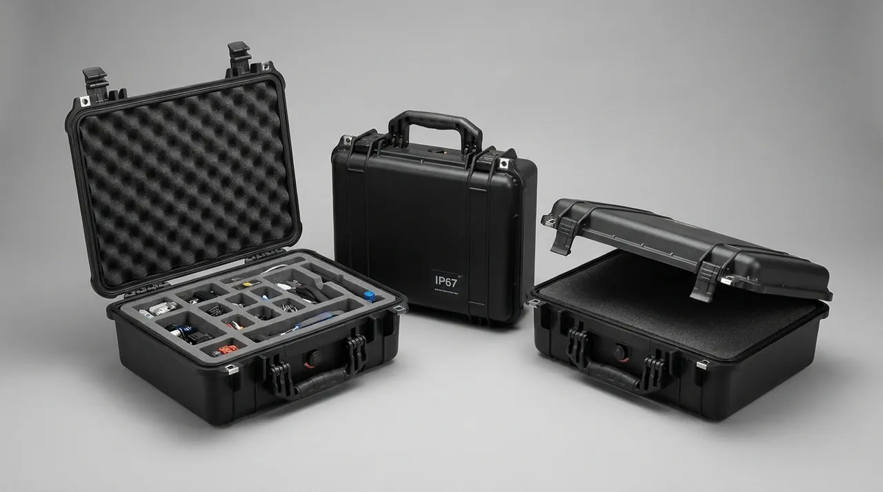
Heavy blocks, commonly found between 0.2 and 2 tonnes, should not rely on the case floor for support. Fix them to a load-bearing pallet or a purpose-made saddle first, then load the assembly into the case, with anti-slip pads between pallet and case floor to stop the whole load creeping in transit. If blocks and bearing face plates must travel together, store the plates vertically in their own slots rather than flat on top of the blocks; plates usually carry a tighter flatness tolerance than blocks and a single over-stack can put them out of tolerance.
| Component type | Typical unit weight | Bearing face protection | Stacking limit |
|---|---|---|---|
| --- | --- | --- | --- |
| Steel keel block | 0.2 to 2 t | Face down on continuous polyurethane band | Single layer preferred, upper offset under one third |
| Concrete or timber block | 0.3 to 3 t | Corner guards and soft end pads | Two layers maximum, continuous dunnage between |
| Dock block bearing plate | 50 to 400 kg | Face down with peelable protective film | Vertical slots, no flat stacking |
| Dock gate hinge base | 80 to 800 kg | Bore plugs and edge guards | Single layer on saddles |
| Dock gate roller assembly | 30 to 300 kg | Curved saddle, 90 to 120 degree wrap | Single layer, wheel faces must not touch |
Securing Winch Drums, Gearboxes and Brakes
Three areas of a winch assembly should never be treated as ordinary bulky iron: the drum rope groove, the gearbox parting face and oil seal lips, and the brake friction faces. The rope groove is the wire rope mating surface, and any score creates local stress concentration that shortens rope life and produces broken wires early. A corroded gearbox parting face leaks after reassembly. A seal lip is a very thin elastomer that deforms permanently under prolonged side loading, showing up later as leakage and shaft journal wear. All three defects can be created in transit and none of them appear immediately.
Handling should follow the principle of securing parts in their service attitude. Support the drum along its axis on two curved saddles with a wrap angle between 90 and 120 degrees and a soft contact lining, so load spreads around the shell rather than concentrating near the end flange welds; place the saddles as close to the drum ends as practical to reduce mid-span bending. Set the gearbox down in its installed attitude and bolt it through the foot mounting holes to the case floor. Do not lay it on its side, which puts the seal and shaft extension under a side component of the gearbox weight for the whole journey. Store brakes and clutches with friction faces facing up or sideways, and keep every rust preventive, vapour phase emitter or mould release away from friction material.
Limit switches, encoders and proximity sensors belong in their own small cavity, positioned in low-shedding closed-cell foam, never in a cavity with heavy metal parts, because vibration accumulates damage at pins and housings. For lifting, use lifting eyes or wide slings around the drum ends. Never pass wire rope or chain across a rope groove or gearbox housing, and never use ports, sensor brackets or guards as lifting points. These points are best issued as an illustrated packing work instruction rather than a verbal briefing, because the crew loading the case is rarely the engineer who wrote the specification.
Dock Gate Parts: Zoning Hinge Bases, Rollers and Seals
Dock gate parts share a profile of long dimensions, low stiffness and surface condition that directly determines function. The fitted bore of a hinge base is the rotation datum for the whole gate movement, and a damaged bore wall or chamfered bore edge produces play that accelerates pin wear. A roller tread carries the load and rolls, so any impression becomes a cyclic shock as the gate opens and closes. Seal base plates and seal rubber determine leakage after closing, the plate through flatness and the rubber through elasticity and surface integrity. Because the three fail in completely different ways, they must be placed in separate cavities rather than mixed.
Hinge bases need attention to both bores and outlines: plug or wrap the bores against dust and moisture, fit soft rings around bore chamfers, and add edge guards along the outer profile. Rollers and slide blocks should sit on curved saddles, with tread faces never touching each other and never pressing directly onto a hard case floor. Seal base plates and stainless parts are handled to a clean-part standard: any saddle, slot or strap touching them should be stainless, polyurethane or engineering plastic; wrapping paper should be chlorine-free and sulphur-free neutral paper; and where carbon steel lifting gear is unavoidable on site, it must be separated by a soft interface, with carbon steel never allowed to slide across a stainless surface.
Seal rubber components need their elasticity protected, not their shape. Rubber seal strips and P-profile seals should be coiled and laid flat, with a coil inner diameter of at least 300 mm as a practical baseline, because a tight coil leaves permanent bending stress inside the rubber. Never hang them on hooks or stretch them to shape, and never stack weights on top. Packaging should block both ultraviolet light and ozone, which dark polyethylene film or aluminium laminate film can do; films that may release chlorine or plasticiser must not share a cavity with stainless parts. Storage temperature around 10 to 25 degrees Celsius is a sensible working range, and the area should be well away from welding stations, electric motors and distribution cabinets as ozone sources, a point most often missed at dock installation sites where seals are simply laid out next to welding work while waiting to be fitted.
Hydraulic Cleanliness Control and Port Capping
Hydraulic parts face a completely different risk from heavy machinery: they do not mind pressure, they mind particles. A valve block or cylinder that has been flushed and certified at the works typically leaves with a cleanliness class between ISO 4406 -/17/15 and -/16/13 (typical values, depending on component grade), and one uncapped port, one open hose end, or even debris shed from a liner is enough to degrade that class to a level the site cannot accept. Once contamination enters, the symptoms are sticking spools, blocked orifices and creeping cylinders, and the diagnosis cost is far higher than the packing cost ever was.
Capping and isolation requirements are straightforward. Cap every port before dispatch with a metal or nylon plug carrying an O-ring; never use cotton waste, paper or ordinary tape as a temporary stopper, because cotton leaves fibres and paper absorbs moisture and creates a rust source at the port rim. Fit blind flanges with gaskets to flanged interfaces and tighten bolts in a diagonal sequence. Cap pipe ends with plastic covers that will not crush in transit. Keep complete valve groups sealed in a dedicated clean cavity that contains no paper labels and no low-density foam; use polyester labels or place labels outside the cavity. Choose low-shedding, closed-cell, non-hygroscopic liner materials and avoid plasticised PVC grades that may interact with hydraulic oil.
| Hydraulic component | Reference cleanliness target (ISO 4406) | Port capping method | Special notes |
|---|---|---|---|
| --- | --- | --- | --- |
| Proportional and servo valve group | -/16/13 or better | Nylon plug with O-ring plus blind flange | No cotton or paper, dedicated clean cavity |
| Hydraulic cylinder assembly | -/18/15 (typical) | Welded plug or dedicated screw plug | Rod retracted or sleeved, rod wiped clean first |
| Gear pump and piston pump | -/17/14 | Plastic caps plus port plugs | Protect shaft extension, guard keyway separately |
| Hydraulic hose assembly | Per system, -/-/16 common | End caps plus coupling protectors | Coil radius no tighter than minimum bend radius |
| Accumulator | Supplied at works cleanliness | Port plugs plus gas valve guard | Pressure vessel documents enclosed, no tipping or rolling |
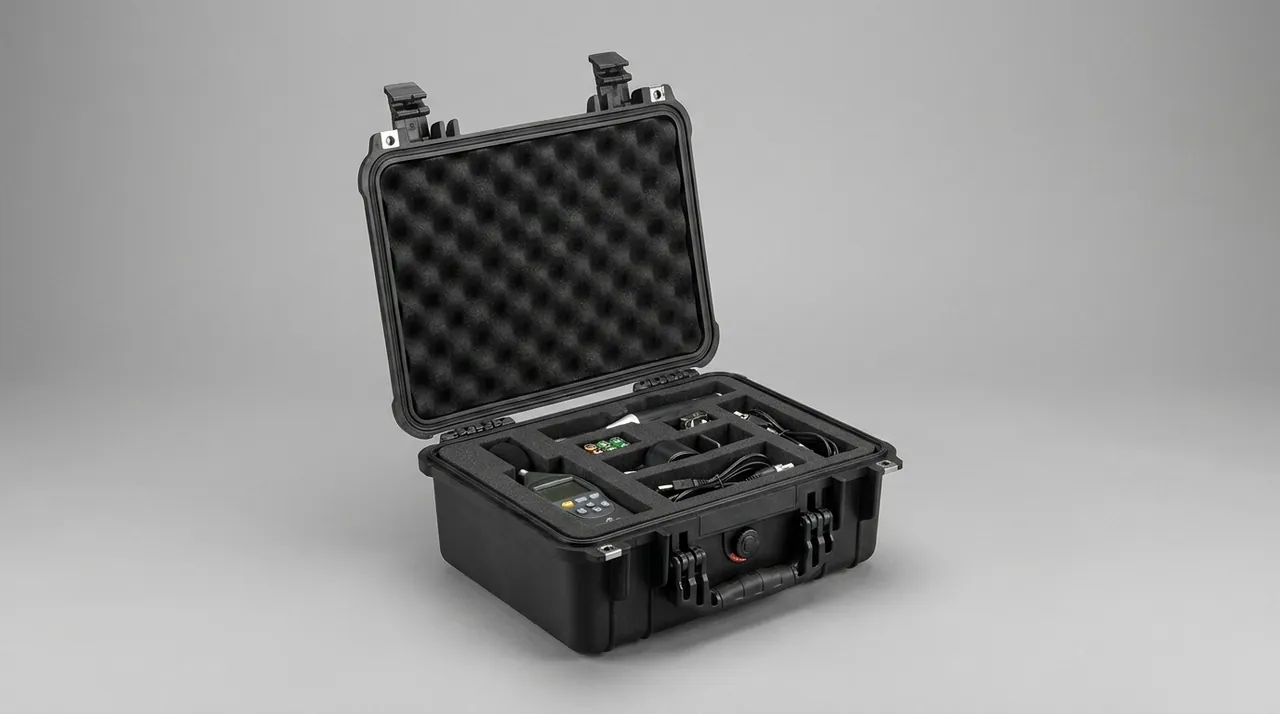
For projects with demanding cleanliness targets, the purchase specification can require a works cleanliness report, a defined sampling ratio for verification after arrival, and an unpacking procedure carried out in a wind-free, dust-free area with immediate re-capping if the system is not connected straight away. When JUNZHIJIA builds custom liners for dock hydraulic components, the clean cavity and the load-bearing cavity are normally made as separate units that do not communicate, each with its own opening sequence marked on the case, so the site never has to open every cavity to reach one valve.
Hoses, Accumulators and Precision Valve Assemblies
Hose assemblies fail in a completely different way from rigid pipe, because what hurts them is a kinked bend and a damaged coupling. Coil radius must never be tighter than the manufacturer's minimum bend radius, commonly six to eight times the hose outside diameter as a rule of thumb; a tight coil leaves residual stress in the reinforcement layers and shows up later as a bulge or an early burst under pressure pulsing. Cap every coupling to protect the sealing face and threads, and place separators between coils so couplings do not press on each other. Keep hoses out of cavities containing sharp-cornered metal parts and do not crush the middle of a hose with a strap.
Accumulators are pressure vessels. Confirm the pre-charge state before transport against the specification, and dispatch the nameplate and works inspection documents with the unit. Do not vent or charge arbitrarily in a way that could later be misread. Clamp them with a bracket plus anti-roll saddle and never invert them, since liquid can migrate into the gas side and cause operational faults. Heavier accumulators should be fixed to their own load-bearing pallet and loaded into the case as a unit rather than relying on local support from the case floor.
Precision valve assemblies must leave the works in exactly their delivered condition. Seal the complete assembly in a cavity with a gasket, and if a chlorine-free, sulphur-free vapour phase rust preventive is used inside, keep it away from rubber seals and electrical connectors, because compatibility problems in a mixed load are the hardest kind to trace. Apply peelable film to machined and mounting faces, using a low-tack grade that leaves no adhesive residue. For handling, use the dedicated lifting eyes on the body or support the base; never lift by solenoids, terminal boxes or ports.
Case Shell and Hardware Selection in Salt-Laden Humidity
Corrosion severity around a drydock exceeds that of an ordinary coastal warehouse, because the environment combines vapour with chloride-bearing wash water and wet sand. Shell material should be chosen for chloride resistance rather than for ordinary rain. Modified polypropylene or copolymer polypropylene performs consistently in this environment, whereas ordinary nylon and some glass-filled grades lose strength faster under combined ultraviolet and salt exposure. External hardware on the case often fails before the shell does: galvanised steel hinges and latches develop white rust quickly in chloride, and rust water then runs down the case wall and stains it. Exposed hardware should therefore be 304 or 316 stainless, or a multi-layer coating system verified by scratched salt spray comparison.
Gasket material matters just as much. EPDM and silicone outperform ordinary nitrile and reclaimed rubber on weather resistance and compression set. A double-lip gasket with a sand-relief step lets grit find a way out instead of holding one lip off its seat and defeating the whole seal. Hinges and latches are the first items to fail under repeated opening and closing, and their load capacity, pin clearance and corrosion combination directly set case service life, so selection and acceptance points are worth reviewing against the structural notes in toolbox hinge, latch and seal selection. Corrosion resistance is normally verified by neutral salt spray to GB/T 10125, but it is important to state that salt spray provides a ranked comparison between options rather than a service life prediction; comparing hinge opening torque before and after exposure often explains more than appearance ratings alone.
For cases stored outdoors at the dock for long periods, three further points matter. Fit a drain plug at a low point so the case can be washed, dried and resealed. Place insulating washers between fasteners of dissimilar metals so a galvanic couple cannot form. Choose a light shell colour to limit solar heating and the breathing effect that follows. Gaskets are consumables and should have a replacement interval and spare parts supply agreed in the purchase documents; the assessment criteria in protective case service life assessment provide a useful framework.
Lifting, Saddles and Support Design for Heavy Components
Once a heavy part is inside the case, the load path must be complete from the workpiece through the liner, through the case floor, into the pallet and on into the transport vehicle. The link most often ignored is dynamic amplification: on road transport, load peaks caused by uneven surfaces commonly reach 1.5 to 3 times static load as an empirical range, and the moment of landing is higher still. If the liner is designed for static load only, it compacts in transit, the workpiece shifts, and the case floor may crack. The amplification factor should be written into the load check explicitly.
Four practices follow. First, provide load-bearing beams or a load-bearing pallet so heavy parts transmit load through the pallet directly to the vehicle rather than through case walls and corner fittings. Second, size saddle contact area against contact stress, using 2 to 5 MPa as a working allowable for soft materials touching machined faces (empirical range), and derive contact width from that. Third, keep lashing angles between 30 and 45 degrees; never lash straight down, because a vertical strap only provides friction restraint and loses grip as soon as the liner compacts. Fourth, mark lifting points and the centre of gravity on the outside of the case, and if a heavy part is offset, add ballast or rearrange cavities so the case does not tilt when lifted.

Stacking must also be specified. Mark the permitted number of stacked cases on the outside, based on the compressive capacity of the lowest case in the stack rather than on an empty case compression test. Heavy cases belong at the bottom. If site constraints force a heavy case upstairs, use racking or a dedicated stacking frame; never place a heavy case directly on a hollow case. Long heavy items such as a batch of seal base plates or guide rails must not be supported at a single point with unsupported spans, and must not be allowed to sag in the middle; add support points so the span between them stays within a defensible limit.
Isolating Dissimilar Metals in Mixed Loads
The most common mixed load in a drydock project is stainless steel plus carbon steel plus aluminium, and the interactions inside that combination in a chloride-laden damp environment are routinely underestimated. Rust debris and free iron from carbon steel contaminate stainless surfaces and trigger pitting. Where stainless and carbon steel touch and a damp electrolytic path forms, carbon steel acts as the anode and corrodes faster. Aluminium and stainless steel sit further apart on the galvanic series, and the aluminium side corrodes more visibly. None of these effects requires immersion in water; a film of condensate cycling on and off inside the case is enough.
Isolation has to be designed in rather than improvised on site. The liner should provide separate cavities by material, with a rigid divider between them and a soft sealing strip along the top of the divider to create a weak barrier. Every saddle, slot and strap touching stainless or aluminium should be stainless, polyurethane or engineering plastic, and fasteners of dissimilar metals should carry insulating washers or sleeves. Wrapping paper and pads should be chlorine-free, sulphur-free neutral material, and chlorine-bearing plastic film should not be used for long-term wrapping because chloride concentrates in condensate trapped under the film. Where cleanliness matters, a free iron test (ferrocyanide colour reaction) on stainless surfaces after arrival is a practical check; any colour development means free iron contamination and the part should be pickled and passivated again before installation.
Matched fastener sets, pins and splice connections should be compartmentalised by size with quantity marking. Mixed compartments inevitably lead to mixed use on site, for example a carbon steel bolt fitted to a stainless flange, which is far from rare during dock gate and seal installation. Compartment design and material choice for this kind of liner are covered in custom foam insert design points.
Liner Zoning and Weight Distribution
The liner is the most technically loaded part of this type of case, because it simultaneously locates, cushions, isolates and carries. Material selection therefore has to be assessed function by function. Closed-cell EVA and polyethylene foam absorb very little water and resist chemicals well, which suits damp and chloride-bearing environments. Polyurethane foam cushions and recovers better, but in high humidity an unsealed surface can absorb moisture and then act as an internal moisture source. Comparison dimensions for these two families are set out in case foam material comparison. A typical drydock case uses high-density closed-cell foam or a composite rigid support block for load-bearing cavities, a low-shedding cleanable rigid divider with a soft facing for clean cavities, vertical slots for long members, and compartment trays for small parts.
Two hard rules apply to zoning. First, heavy parts go low and central: put the heaviest block or hinge base at the bottom centre, and place light or fragile parts in upper and outer positions, so the overall centre of gravity sits near the geometric centre and as low as possible. Second, incompatible parts never share a cavity: hydraulics away from rusting carbon steel, stainless away from carbon steel, rubber away from vapour phase rust preventive, electrical items away from heavy magnetic parts. Fix these rules at the design review stage, so that nobody rearranges cavities at loading time simply because a part fits.
Fit between liner and shell also matters. Any gap between the liner and the case wall becomes a space for movement in transit, letting the workpiece shift and strike the cavity wall. Add a thin filler layer or use a compressible edge strip so the liner sits in slight interference. Where one case must carry different components on different voyages, a removable divider system is better than a single moulded liner; the general approach is described in removable divider system.
Sealing, Pressure Equalisation and Internal Humidity
A drydock component case faces a continuous moisture source rather than an occasional rain shower, so its sealing logic differs from a simple waterproof box: it must keep external water out while managing humidity inside. The gasket should tolerate repeated opening and grit abrasion, using a double lip with a sand-relief step so that grit has an escape path instead of holding a single flat lip off its seat and defeating the case. The humidity target is to hold the sealed cavity below 45 percent relative humidity, or to keep the internal dew point more than 5 K below the lowest expected ambient temperature as an engineering guideline; both criteria are useful in a dock area with a large daily temperature swing.
Pressure equalisation is the frequently overlooked element. The better the seal, the more pronounced the internal pressure swing from day-night temperature change, and repeated pressure cycling prises the gasket open at its edges and draws moist outside air into the case. A breathable pressure equalisation device uses a hydrophobic membrane to equalise pressure slowly while blocking liquid water and dust, as described in case pressure equalisation valve. Desiccant quantity is estimated against free cavity volume; the table below gives the empirical ranges commonly used in engineering, and actual figures should be adjusted for the sealing class of the case and the storage environment.
| Storage condition | Reference desiccant quantity | Humidity indicator bands | Target internal RH |
|---|---|---|---|
| --- | --- | --- | --- |
| Sealed cavity, dry inland site | 0.6 to 1.0 kg per cubic metre | 10/20/30/40 | 45 percent or below |
| Sealed cavity, humid coastal site | 1.2 to 2.0 kg per cubic metre | 10/20/30/40/50/60 | 40 percent or below |
| Long-term open yard storage | 2.0 to 3.0 kg per cubic metre with spare cartridge bay | As above, plus photographed record | 45 percent or below, dew point 5 K under ambient minimum |
| Hydraulic clean cavity | 1.0 to 1.5 kg per cubic metre, low-shedding grade | 10/20/30/40 | 35 percent or below |
The value of a humidity indicator card is that it turns the internal microclimate into a readable record. Saturated desiccant looks almost unchanged, so a site cannot tell by eye whether it is still working; a banded indicator card lets the crew decide, before opening, whether components should be moved to a dry area first. Opening records should include a photograph of the card, the opening date and the operator, giving traceable acceptance evidence. For long storage, fit a replaceable desiccant cartridge and a viewing window, because repeatedly lifting the lid to check humidity is itself a common way of letting moisture in.
Marking, Inspection Checklists and Opening Acceptance
Marking is the only channel through which the packing intent reaches transport and site crews, so it should follow the handling pictorial markings of GB/T 191 supplemented with case-specific symbols. Essential items include centre of gravity and lifting points, this way up and no tipping, keep dry, permitted stacking height, and gross weight and external dimensions, together with the component list, batch number, sealing date and latest opening date for each sealed cavity. Clean hydraulic and stainless cavities should also carry working notes such as no chlorine-bearing cleaning agents and no bare-hand contact with machined faces.
A checklist lands better than marking alone. Before loading, confirm item by item that every oil port is capped and counted, bearing faces sit on continuous support with dunnage aligned between layers, stainless and carbon steel are in separate cavities, seal rubber is shielded from light and not compressed, desiccant and indicator cards are installed with the initial colour recorded, no paper labels or low-density foam remain inside, and hinges and latches are torqued and cycle-tested. During loading, record the actual content and weight of each cavity for later cross-checking. After loading, run a pre-closing recheck signed by a second person.
The opening sequence deserves to be specified as well. Read the humidity indicator and pressure equaliser status first, then decide whether the whole case should move to a dry area. Open cavities by number, taking light items before heavy ones so that nothing drops when a lower cavity is emptied. Once a hydraulic cavity is open, check immediately that all port plugs are present, look for leakage traces, and complete the first visual inspection inside a clean area. The acceptance record format can be aligned with the test-to-acceptance correspondence suggested in ISTA transport testing procedure.
Transport and Salt Spray Test Evidence
Three tests are worth naming in the purchase specification, so that a packing scheme moves from looking acceptable to being verified. The first is corrosion performance, run as neutral salt spray to GB/T 10125 with samples covering the case hardware (hinges, latches, handles) as well as the material combination of liner and workpiece; after exposure, measure hinge opening torque change as well as appearance rating. The second is transport performance, either drop and stacking tests to the GB/T 4857 series or a full distribution cycle simulation to the ISTA series or ASTM D4169, with the profiles described in ISTA transport testing procedure and ASTM D4169 distribution cycle simulation. The third is sealing and pressure equalisation, verified to IP rating under IEC 60529 or GB/T 4208 with a separate functional check of the equalisation device after thermal cycling.
Test programmes should be cut to the actual route rather than copied from a template. Where components travel a short road leg straight to the shipyard, stacking and vibration dominate. Where they go by sea with transhipment, longer temperature and humidity cycling plus stricter stacking duration are needed, because the upper layers of a container run well above average outside temperature and humidity. If a case will sit outdoors at the dock, add ultraviolet ageing and rain testing, and state whether the humidity indicator should be checked mid-storage.
Three quick checks when reviewing a packing proposal: what cleanliness class the hydraulic cavity targets and how the ports are capped; what material and what width of continuous support carries the keel block bearing face; how much desiccant is inside and what humidity criterion counts as a pass. A proposal that answers all three with numbers is a proposal that can be accepted.
FAQ
Q: Why can a timber baulk not be placed directly under a keel block bearing face?
A: A timber baulk contacts the bearing face along a line rather than over an area, so landing impact drives stress well past yield near that line and leaves an impression that later concentrates hull load. Timber also brings two secondary problems. It absorbs moisture and then becomes a stable internal moisture source, so a long-sealed case can develop rust or mould at the interface. Its moisture content also changes, so a support that was correctly fitted at dispatch can shrink away within weeks, letting the block move inside its cavity. Where timber support is unavoidable, choose a moisture-controlled hardwood with anti-fungal treatment, and put a non-absorbent, non-shedding soft pad between timber and machined face so contact stress is spread. A better default is a polyurethane elastomer band at Shore A 80 to 90 covering more than 60 percent of the effective face width, with continuous dunnage aligned vertically between layers. Finish with a load check against the transport amplification factor.
Q: Can hydraulic ports be temporarily plugged with cotton waste or paper?
A: No, and on projects with demanding cleanliness targets it should be explicitly prohibited. Cotton waste sheds fibres that migrate into valve bodies, gather at orifices and cause flow faults and sticking spools. Paper absorbs moisture and creates a local rust source at the port rim, and the rust flakes enter the system with the oil during commissioning. Both types of contamination cost far more to trace than a plug costs to buy, and they typically surface only at the commissioning stage. The correct method is a metal or nylon plug with an O-ring, a blind flange with gasket on flanged interfaces, and a plastic cap with a closed end on pipe ends. Plug quantities should be recorded against the drawing and verified on arrival. If temporary protection is genuinely necessary in transit, use a purpose-made elastic sealing cap rather than ordinary tape wound around threads. Unpack in a wind-free, dust-free area and re-cap immediately if the system cannot be connected at once.
Q: How much does ISO 4406 cleanliness degrade during transport?
A: The degree depends on capping quality and liner shedding, so no universal figure can be quoted, but the mechanism is settled: wherever an opening connects the interior to outside air, particles enter by settlement and by airborne carriage. Vibration during transport keeps dust suspended inside the case, and debris shed from soft packing materials or generated by internal rubbing can all be drawn into an open port. Engineering practice is therefore not to estimate degradation but to remove the paths that cause it: cap every opening, place valve groups in a dedicated clean cavity, select low-shedding closed-cell liners, and control internal humidity to suppress the formation of corrosion particles. Where a demanding class applies, require a works cleanliness report and a defined sample check on arrival in a clean booth, comparing results with the dispatch figure. If the check fails, flush or replace components in a clean environment before assembly rather than installing them and relying on a system flush to recover.
Q: What posture should a winch drum be fixed in inside the case?
A: Horizontal, in its service attitude, carried on two curved saddles is the more reliable choice. Keep the wrap angle between 90 and 120 degrees with a soft contact lining so load spreads around the shell rather than concentrating near the end flange welds, and place saddles as close to the drum ends as practical to reduce mid-span bending. Practices to avoid include passing wire rope through the drum or across the rope groove when lifting, which leaves impressions in the groove; standing the drum on its flange face, which puts the full weight onto the end face and spigot and invites distortion; and strapping the drum to a gearbox or brake so it carries extra side load. Limit switches and encoders are packed separately in their own cavity rather than fixed to the drum. After unloading, confirm the storage position offers equivalent support before lifting the assembly again, so nothing is left leaning once the saddle is removed.
Q: What harms dock gate seal rubber most in transit?
A: The worst case is ultraviolet exposure, ozone contact and sustained compression or tension occurring together. Ozone attacks stretched rubber surfaces first, producing fine cracks perpendicular to the stress direction. Ultraviolet light causes surface chalking that progresses inwards. Continuous squeeze or hanging under tension leads to permanent compression set that never recovers. Sealing capability depends on compression recovery, so rubber that has lost its spring cannot press hard enough and the gate leaks after closing. Protective measures include coiling flat with an inner diameter of at least 300 mm as a practical baseline, never hanging or stretching the strip to shape and never stacking weights on it, choosing dark polyethylene or aluminium laminate film that blocks both ultraviolet and ozone, and storing at roughly 10 to 25 degrees Celsius away from welding stations, motors and distribution cabinets as ozone sources. Inspect each piece for hardening, cracking and permanent deformation before installation and reject anything suspect.
Q: Can a dock block bearing plate travel in the same cavity as keel blocks?
A: Generally not advisable. A bearing plate is a thin plate item with a tight flatness requirement, while a keel block is a heavy item that can weigh hundreds of kilograms or several tonnes. In a shared cavity the block weight bears on the plate through a few contact points and creates local bending, and one journey can put the plate out of tolerance. The safer arrangement is to store plates in vertical slots sized with 3 to 5 mm clearance over plate thickness, with soft material at the slot bottom so the plate is carried on its edges, and to give blocks their own cavity on continuous support bands as described earlier. Where space forces a shared cavity, fit a rigid divider between them and place the plate in a slot above that divider, with the divider stiff enough to be supported directly by the case floor rather than indirectly by the blocks. Once cavity positions are fixed, run a loading trial to confirm plate flatness stays within tolerance after a full-load transport simulation.
Q: The dock is very humid, so should the case simply be sealed as tightly as possible?
A: Sealing class has to be matched with internal humidity management, because pushing sealing alone can create new problems. The tighter the seal, the larger the internal pressure swing caused by day-night temperature change, and repeated pressure cycling prises gasket edges open and draws moist outside air into the case, an effect usually described as breathing. The practical combination is a double-lip gasket with a sand-relief step, plus a breathable pressure equalisation device that uses a hydrophobic membrane to equalise pressure slowly while blocking liquid water and dust, together with desiccant dosed against free cavity volume and a humidity indicator card as readable evidence. Target internal relative humidity below 45 percent, or an internal dew point more than 5 K below the lowest expected ambient temperature. For long outdoor storage at the dock, add a replaceable desiccant cartridge and a viewing window so nobody has to keep opening the lid to check humidity.
Q: Is one layer of plastic film enough between stainless and carbon steel in the same case?
A: Usually not. Plastic film provides a physical barrier only, and neither contamination nor galvanic coupling is interrupted. Rust debris from carbon steel migrates through film openings and seams onto stainless surfaces. Closed gaps under the film collect liquid, and condensate working with iron ions inside those gaps becomes a pitting origin rather than a protection. Where carbon steel and stainless steel form a conductive path through a fastener or a metal case fitting, a damp environment will establish a galvanic couple. The robust approach works in layers: put the two materials in separate cavities with a rigid divider and a soft strip along its top to create a weak barrier; use stainless, polyurethane or engineering plastic for every saddle, slot and strap touching stainless; and specify chlorine-free, sulphur-free neutral wrapping paper. On cleanliness-critical projects, run a ferrocyanide free iron test on stainless surfaces after arrival and pickle and passivate again if colour develops.
Conclusion and Further Reading
Four rules summarise the whole scheme: zone by cleanliness class, separate by material, match support to stiffness, and set corrosion protection from storage duration. JUNZHIJIA builds dock and offshore component cases with clean, stainless and load-bearing cavities as separate liner units, supplying matched seals and port plugs per component family and preparing liner proposals. OEM and ODM supply is available.
Related Reading