

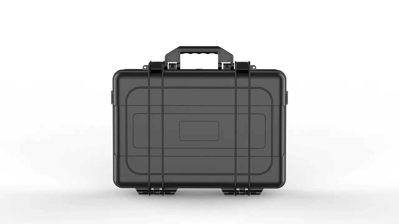
A feed mixer sits at the centre of daily operations on a dairy farm or in a feed processing plant. It runs in dust, humidity and vibration, starting and stopping many times a day, and it is expected to keep weighing and blending accurately for years. What often decides whether it does is a stage nobody photographs: the journey of its spare parts from the factory to the installation site. Auger assemblies, load cells, gearmotors and discharge-door components travel hundreds or thousands of kilometres by road, get handled several times, and may wait outdoors for weeks. A single careless bump can knock a calibrated sensor out of tolerance or bend a long screw flight. Writing as a protective case manufacturer, JUNZHIJIA walks through these risks and explains the container-design logic that answers them.
1. How Feed Mixer Parts Actually Get Damaged
Feed mixer components are not a single category of goods. Each responds to transport stress in a different direction, and understanding that is the starting point of any packaging decision. Choosing a box first and improvising the packing method afterwards is the most common mistake we see.
An auger, or screw conveyor, is the classic long, slender, overhung structure. The flight is welded to a central shaft, and its outer edge sits far from the axis, so local stiffness is low. Two failures dominate in transit. The first is progressive bending: laid horizontally with support only at the ends, the middle sags under its own weight, and vehicle vertical accelerations add to that deflection. The second is pitch distortion, where the flight edge rests against steel or an adjacent part and the thin leading edge deforms, changing the pitch between turns.
Once pitch drifts beyond a modest limit, throughput pulses. Material builds unevenly along the trough, the motor sees fluctuating load, and in bad cases the screw jams. None of this is visible from across a workshop floor, which is why it survives inspection and only appears as poor mixing performance months later.
Load cells sit at the opposite extreme. A load cell is a machined elastic body that converts tiny strain into an electrical signal through bonded strain gauges. A low-capacity unit, such as a 100 kg cell on a batching scale, can enter the plastic region when overloaded by roughly twenty per cent. After that the zero point shifts and calibration cannot fully restore accuracy. One night spent under a heavy gearmotor can destroy a cell, and the failure is invisible when the crate is opened.
Gearmotor problems concentrate at the output shaft and oil seal. A side impact increases runout at the shaft end, moving the gear contact pattern off the centre of the tooth flank and onto the edge. The seal tells a similar delayed story: once the lip is deformed or contaminated with grit, the unit still looks and sounds fine, and only after a few hundred operating hours does oil begin to weep.
Discharge-door assemblies carry the most invisible risk of all. Plate flatness, seal compression and actuator stroke accuracy all change when parts are stacked under load. A slightly twisted plate leaves a gap when it closes, so dust escapes, material absorbs moisture and weighing drifts. The symptom is described as the scale being "always a little off", and the investigation usually starts in the control cabinet rather than at the door.
2. Turning Damage Modes into Design Targets
Translated into container-design language, those failure modes produce four hard targets that form the skeleton of the whole approach.
The first is no overload transfer. No load cell, no calibrated assembly and no precision component should ever carry a force greater than its rated load while inside the case. That requires an explicit division of labour: some parts bear load, others must not. It sounds obvious, yet it is violated constantly because putting heavy and light items together is the cheapest handling option.
The second is no relative movement. Damage usually comes from repeated rubbing rather than a single blow: one drop leaves one dent, but hours of micro-movement produce surface wear, coating loss and loosened fasteners, surfacing weeks later as a machine that started acting up. Constraining movement depends on cavity fit, not loose fill, which creates exactly the play space in which parts hammer each other.
The third is no trapped moisture. Feed equipment parts are mostly carbon steel and cast iron, and machined surfaces flash-rust as humidity rises. Corrosion in storage is more insidious than corrosion in transit: rain on the road leaves an obvious mark and triggers an inspection, while humidity climbing slowly in a warehouse triggers nothing, and by the time the case is opened the threads have seized and the keyways have rust pits.
The fourth target is verifiability. A protection scheme has to survive drop, vibration, stacking and salt-spray testing rather than claiming robustness from experience. For export shipments the packaging should also map onto recognised distribution test methods, including the familiar drop and stacking procedures and the airworthiness-style case standards used in aviation logistics.
Putting those four targets onto a drawing exposes a set of natural conflicts. Thicker liners resist impact better, but the thicker the liner the harder it is to hold cavity tolerance, so parts actually gain free play. Heavier steel adds stiffness, but a heavier case is more likely to be handled roughly by a tired operator, which raises the real-world damage rate. Good design is therefore not a one-way push towards maximum strength, but a balance between stiffness, weight, fit and cost, confirmed by testing rather than asserted on a specification sheet.
It helps to define the transport environment before choosing anything. Road vibration, rail shunting, container handling and forklift staging impose different frequency and acceleration profiles, so a case designed around one may be marginal in another. Where the route is known we ask for the mode split, the expected number of handlings and the worst-case drop height, because those three numbers shape cradle geometry and liner thickness more than any generic strength requirement.
Separate transport damage from handling damage in the risk register. Transport damage scales with distance and road quality; handling damage scales with how many times a case is lifted, opened and moved. A two-handling domestic delivery and an eight-handling sea journey need different solutions even for identical parts, and treating them as one line item is how projects over-protect the short hop and under-protect the long one.
3. Auger Assemblies: Cradles and Multi-Point Support
The auger is the hardest item in the whole scheme because it must neither bend nor be scratched.
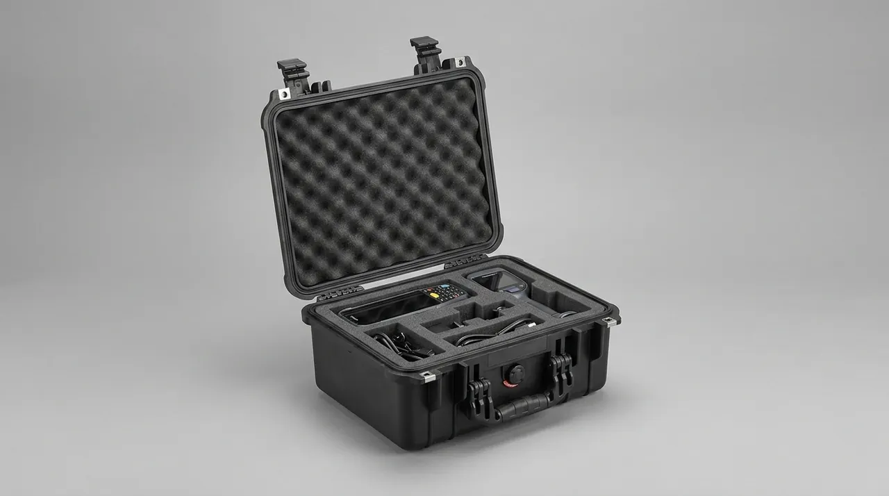
Our approach is to stop treating the auger as a loose item and instead give it a load-bearing cradle running the full length of the case. The cradle is welded from rectangular steel tube and anchored to the case frame at both ends, with nylon or ultra-high-molecular-weight polyethylene blocks spaced along it. The blocks carry a V or half-round groove matched to the auger outside diameter, with relief pockets where the flight edge passes, so the thin edge never lands on a hard support.
Support spacing depends on the slenderness ratio and self-weight of the specific auger. The rule is to keep maximum deflection within one thousandth of the span under self-weight plus vertical acceleration, while keeping the first natural frequency clear of the bands road transport excites; if they coincide, resonance multiplies deflection several times over. More supports is not automatically better, since every support is another contact point and another chance of scuffing, so spacing is calculated per part rather than copied from a template.
For multi-section augers, or extended versions assembled on site, the cradle divides per section. Each gets its own cavity, supports and axial restraint, so one section cannot push another during a rough ride. Threaded ends and flange faces get plastic caps over the features easiest to bruise.
Material choice for a long case leans towards a steel frame with coated panel skin, balancing rigidity against weight. Where the customer needs empty-case return shipping and lighter handling, an aluminium-magnesium frame is the alternative. The base is thickened and carries embedded beams, so cradle load passes into the bottom structure rather than pressing on the side walls.
Handling needs design attention too. A long auger case has a centre of gravity that rarely matches its geometric centre, so it is marked with the centre line and lifting points, plus forklift pockets at both ends. Those pockets get reinforced edges, because repeated fork entry otherwise splits the opening and damages the seal face. For very long augers we recommend a split case with alignment dowels, so the halves can be stored and moved separately.
In storage, an auger case should never be laid on its side. Once it is, the cradle stops carrying the main load, the deflection direction reverses, and the flight edge can press against the wall. The case exterior is marked with permitted storage orientations and a stacking limit, and a pallet goes underneath. For long-term storage we also fit a humidity indicator card so desiccant is replaced before relative humidity climbs into the danger band.
Field experience points to one more failure that drawings rarely capture: the auger that arrives straight but is then bent during installation. A long screw is often lifted by a sling around its middle, which puts the whole self-weight of both overhangs into one section. Even a gentle lift that way can add a permanent set. We therefore keep the cradle in service during installation and specify that the auger be lifted on two slings at calculated positions, or moved together with its cradle, then separated only at the coupling. The protection therefore does not end at the case mouth; it continues through the first hour on site, which is statistically one of the riskiest moments in the whole chain. Putting that instruction on the case lid costs almost nothing and prevents a class of damage that is otherwise attributed to the supplier.
4. Load Cells: Segregated Cavities and Gentle Restraint
If the auger tests stiffness, the load cell tests restraint. Here the case has to do less, not more.
Low-capacity load cells are packed one per cavity, in cavities machined from a solid block of EVA or polyurethane foam. The cavity is matched to the cell profile with roughly five per cent pre-compression at the contact faces. The purpose is to keep restraint near zero while the case is at rest and let it build up progressively only when acceleration occurs, avoiding the creep that continuous pressure would cause.
A load cell must never share a cavity with a heavy part. Our field data includes many cases where a cell sat beside a gearmotor with only a cardboard sheet between them and arrived with a visible zero shift. The cause was not a direct impact but the tiny continuous movement of the motor under vehicle vibration, repeatedly squeezing the elastic body. That is precisely where compartmentalisation earns its cost.
Cabled cells run through a separate channel with a strain relief at the exit, so that pulling force never reaches the sealed connector or the weld. Junction boxes, transmitters and display instruments go into their own cavity, fully separated from mechanical items.
For moisture control, precision cavities carry desiccant and a humidity indicator card, while the case is built to IP67 with a pressure-equalisation valve to handle differential pressure. Even through day-night temperature swings and a humid rainy season, relative humidity inside stays in a safe band. Each cavity also carries a weather-resistant label with the original calibration data, serial number, rated capacity and wiring definition, so the parts can be verified the moment the case opens.
Installation torque deserves a mention here because it belongs in the design. A load cell is normally fixed between the scale frame and the hopper, and applying torque directly to the cell body introduces preload by hand. Our documentation therefore specifies where and in what order torque is applied, and where necessary supplies a spacer block so that clamping force travels through the block rather than the elastic body. Reserving space for those accessories inside the case is itself part of the protection scheme. For a machine with several cells, we recommend numbering them by mounting position and packing them in order, because cells on different weighing points may differ in capacity and sensitivity; a swap will still power up, but the machine's metering accuracy will drift from its design value, and that kind of deviation is very hard to trace on site.
5. Gearmotors and Drive Parts: Load Path First
The gearmotor is usually the heaviest item in the case, and its logic runs opposite to everything else: it should sit on structure, never hang from it.
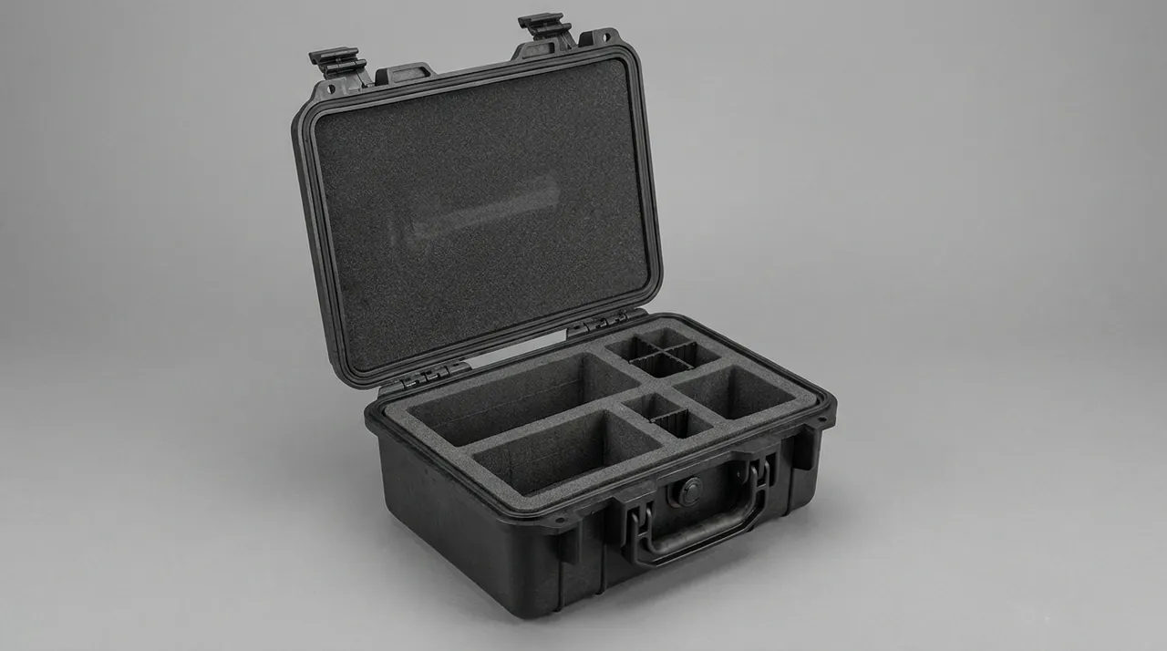
The motor rests on its flange face or mounting feet directly on the base beams, with a vibration-damping rubber sheet between. Beam section is selected from motor mass plus a transport shock factor, and what is checked is the base deflection of the case under four-point stacking, not merely the strength of the case itself.
The output shaft is the most vulnerable direction because it overhangs and is usually smaller in diameter than the housing. Both axial and radial movement must be restricted. Axially, a set screw or end plate blocks shaft movement; radially, a half-round clamp with a soft liner supports the shaft close to the seal. The clamp must not be over-tightened, because that applies a radial load by hand and damages the bearing just as effectively. The acceptance test is simple: with the clamp fitted, the shaft should not turn at all, but no witness mark should be left on the shaft surface.
Fan cowls and terminal boxes are thin-wall or plastic parts and get their own foam blocks that carry no stacking load. Fan blades are thin cantilevered elements, and a single compression event bends them into the housing, so the case must preserve clear space in the blade direction.
Pulleys, sprockets and couplings are mid-weight items that can share a level, but with perforated trays between layers and a fixed count per layer, so that they cannot slide against each other and polish their own surfaces. All machined faces and keyways receive rust-preventive grease before packing. Flexible coupling elements such as spider inserts and rubber blocks are ageing items and should be kept away from metal parts so that they do not sit in long-term contact with oil-based rust preventives.
Every motor should be visually confirmed before packing: fan cowl free of cracks, terminal box cover tight, nameplate legible. Catching these at the factory costs almost nothing; discovering them on site means either shipping the unit back or improvising a repair on a farm, and both are far more expensive than the check.
One more easily missed detail: if a sprocket or gear tooth presses against rigid packing, the tooth tip takes a concentrated load and deforms slightly, which later shows up as increased mesh noise and faster wear. Gear faces therefore always point towards the soft face of the cavity.
Motor weight distribution deserves a note too. Many gearmotors are heavier on the gearbox side, and the flanges are not symmetric. If the cradle is designed around the geometric centre instead of the true centre of gravity, one end carries far more load than the other during acceleration, and the mounting feet take a bending moment they were never designed for. We therefore ask for actual mass and centre of gravity rather than a nominal figure, measuring a sample unit where data is missing.
6. Discharge-Door Assemblies: Flatness and Seal Faces
The discharge door is a flat part, and flat parts hate uneven loading.
If plates are stacked flat, the lower plates bend slightly under the weight above, and once the seal channel distorts, the door can no longer make uniform line contact when closed. Dust escapes at the highest point of the gap, which is where aeration and moisture problems begin. We therefore build vertical slots for door plates, so each plate slides in like a file, held on both sides by foam strips. Standing vertically, the plate's main load direction lies in its own plane, where its bending resistance is greatest, and flatness loss is almost eliminated.
Seals are handled two ways. Loose seals go into a separate cavity to avoid stretching and twisting, while seals already fitted to a plate are covered with a protective film, and the slot entry is radiused so insertion cannot cut the lip.
Cylinders, electric actuators, linkage rods and hinges share a cavity but never touch each other. Actuator strokes are held at full retraction with a mechanical stop, preventing the creep that wears a cylinder bore. Transport attitude should also follow the installation sequence: where the door is fitted early, it belongs in an outer cavity so fitters are not digging through the case at the start of the job.
Fasteners and standard parts live in a clear compartmented tray with an assembly diagram on the lid. On a farm, that small convenience is often appreciated more than the protection itself. Compartment count is set to the quantity needed for one machine, so an empty slot signals a missing item before the build stalls and someone reaches for a substitute bolt, which is very often the source of a later loosening failure.
All adjustable components are marked at their factory positions with a paint pen, so a fitter can compare after installation and see immediately whether anything moved in transit.
7. How Compartments and Liners Are Actually Built
Dividing a case is not simply cutting it into squares. The layout has to match the number, the shape and the handling order of the parts.
We group by system rather than by size: auger cavity, cell cavity, motor cavity, door cavity, accessories cavity. Each opening is independent and none of them interconnect, so a mistake in one cavity cannot affect the whole load. Lids are hinged rather than fully removable, which reduces loss and mis-fitting on site.
Liner material follows the part. EVA foam suits low and medium weight precision items, thanks to good machinability and tight fit. Polyurethane foam offers better rebound and energy absorption for heavier parts and repeated impacts. Low-density polyethylene is appropriate for large items that only need coarse location. Composite liners are used when needed, for example a polyurethane energy layer under a precisely cut EVA locating layer.
On cavity geometry our rule is small contact area, many support points. Small contact areas reduce friction and contamination; many support points distribute stress. For curved parts the cavity is contoured rather than supported on a few flat pads, because flat pads leave local dents on a curved surface.
Cavity tolerance is applied selectively. Precision items get tight tolerances so no free play exists, while heavy structural items get looser ones because their position is set by the load-bearing structure rather than the cavity wall. Making every cavity a tight fit is a common over-design: it makes removal difficult, and an operator in a hurry will force parts in and out, damaging both part and liner.
Case hardware belongs to the protection chain too. Hinges must carry the lid weight plus a one-handed opening action, latches need an anti-release feature, and handles are sized against the loaded weight. For cases in frequent rotation we make wear-prone hardware replaceable, so one broken latch does not scrap an entire case.
8. VCI Rust Control and Sealing Working Together
Most feed equipment parts are carbon steel, cast iron or blackened machined components, so rust prevention is the floor of the whole scheme, especially across sea freight and long storage periods.
We combine vapour corrosion inhibitor technology with physical sealing. VCI film or VCI masterbatch foam releases inhibitor molecules inside the sealed cavity, forming a monomolecular protective layer on metal surfaces, including recesses and threads that are difficult to coat by hand. VCI performance depends on a closed environment, so the case sealing class must match it. If the case breathes, the molecules disperse, and the protection period can drop from two years to a few months.
The main seal is a one-piece moulded silicone or EPDM gasket, never spliced at the corners, with compression set from the material compression-set curve. Latch spacing is calculated, because latches set too far apart let the case mouth open locally between them, one of the commonest causes of an IP67 failure.
Waterproof cases carry a venting pressure-equalisation valve, letting internal pressure track temperature while blocking liquid ingress. For humid regions and shipments crossing climate zones we place humidity indicator cards inside so the user can decide whether to renew desiccant.
The case itself should also drain. The base avoids troughs that hold water, and external ribs channel rain away. When cases are stacked, a ventilation gap between contact faces stops long-term water pockets from corroding the exterior.
A second, subtler interaction happens at the moment of opening. After cold storage, a case moved into a warm humid warehouse warms its internal air, so relative humidity climbs quickly and condensation forms on cold metal. The vent valve solves pressure; condensation is handled by desiccant quantity and placement. We fit separate desiccant packs in each metal-dense cavity rather than one central pack, so a sealing difference in one cavity does not affect the others.
For very long storage or sea freight, reusable humidity indicators and regenerable desiccant boxes can be added. The colour change gives the user a direct read on whether protection is still valid, rather than relying on a judgement call. None of these details is complicated alone, but together they decide whether the scheme covers the full chain from dispatch to installation.
9. Manufacturing Quality Control from First Article to Dispatch
A good design still underperforms if manufacturing deviates, so we run a staged inspection process.
The first stage is first-article cavity verification. Once the liner is machined, a duplicate part at identical dimensions is placed in the cavity to check fit, removal force and play. Production starts only after a hard contact point has been ruled out.
The second stage is packaging testing. A fully loaded case goes through vibration, drop and stacking procedures following recognised distribution test methods, checking whether liners shift, parts deform or seals fail. Export and hazmat scenarios add verification against international transport packaging tests and airworthiness-style case standards.
The third stage is environmental testing. Salt spray evaluates the corrosion resistance of metal and hardware items, while immersion and spray tests confirm whether the sealing class genuinely reaches IP67.
The fourth stage is dispatch inspection. Every case is checked for cavity configuration, liner type, gasket integrity, vent valve function and label content, with packing photographs archived for traceability.
The point of this process is not to pass a test but to make protection repeatable: in a batch delivery the first case and the thousandth should behave identically. That consistency depends on records. Liner machining parameters, gasket batches and hardware supplier changes all affect performance, so they are logged and re-verified when they change, and any material substitution goes through an equivalence assessment rather than being approved on visual similarity.
We also recommend keeping a baseline sample case. When a damage complaint arrives, comparing the problem case against the baseline separates a design defect from a manufacturing deviation from operational misuse, which prevents repeated redesign under uncertainty. That matters most across batches and years, because memories fade while a sample does not.
10. Storage and Stacking: The Underestimated Window
Plenty of damage never happens on the truck. It happens in the warehouse.
Stacking is a long-duration load. Plastic cases creep under sustained pressure, walls bow inward, and eventually the contents are squeezed. Stack height must therefore come from long-term load capacity, not short-term strength. We mark a recommended stack count on the case side and advise pallets and separating boards for multi-layer stacking.
Warehouse humidity matters just as much. Above a critical relative humidity, corrosion rate on metal parts climbs sharply, so stores should be ventilated and dehumidified, and cases should not sit directly on the floor. A gap underneath protects against rising damp.
Handling method belongs in the work instruction. Lifting points, forklift entry direction and permitted tilt angles should all be explicit, so that nobody shortcuts the process by tipping a case onto its side and loading the contents in a direction the design never anticipated.
Rotating cases need maintenance management too. Ageing gaskets, loose latches and damaged liners all reduce protection, so a quick check after each return trip, logged in a rotation record, is worthwhile. For cases in long service, replacing gaskets on a schedule is cheaper than waiting for failure.
Rotation records also feed back into design. If the same liner position fails repeatedly on one model, the original load assumption does not match reality and the cavity or local reinforcement needs revisiting. That insight only accumulates when records exist; otherwise every failure is treated as an isolated event and the problem returns.
For customers running their own rotation pool, three explicit rules are worth setting: permitted stack count, permitted lifting and fork entry methods, and the post-return inspection list. Together they cover most non-transport damage causes at low cost.
11. Matching the Case to the Shipping Mode
The same parts can need different cases depending on how they travel, and mixing modes without adjusting the design is a common source of late-stage failures.
Full container load shipments handle rarely, so impact risk is low, but a container heats in the sun and cools at night, driving condensation cycles a single-seal case will not resist alone. Vent valves and per-cavity desiccant therefore matter more at sea than on a domestic truck.
Less-than-container-load shipments are the opposite: many handlings, mixed stacking with unrelated cargo and no control over what goes on top. Requirements shift outward to reinforced corners, protected hinges and latches, and feet that keep the case stable beside an irregular pallet. Labels matter more too, since strangers will open the case.
Air freight is a third category. Humidity exposure is short, but handling is frequent and the case travels pressurised and temperature-controlled. Unpressurised space still exists on some routes, so a vented case beats a fully rigid one that sees a large differential. Weight also drives cost, which is where aluminium-magnesium frames earn their premium.
Rail and inland waterway shipments add low-frequency, high-amplitude vibration over long duration, so cradle spacing and part-to-part restraint matter most, because exposure lasts days rather than hours. When the mode is unspecified we assume the worst realistic combination, then let the customer trade weight back for cost once the route is known, recording that assumption on the drawing.
12. Joining Up with On-Site Installation
A case proves its worth the moment it is opened, so the design has to think about the installation sequence.
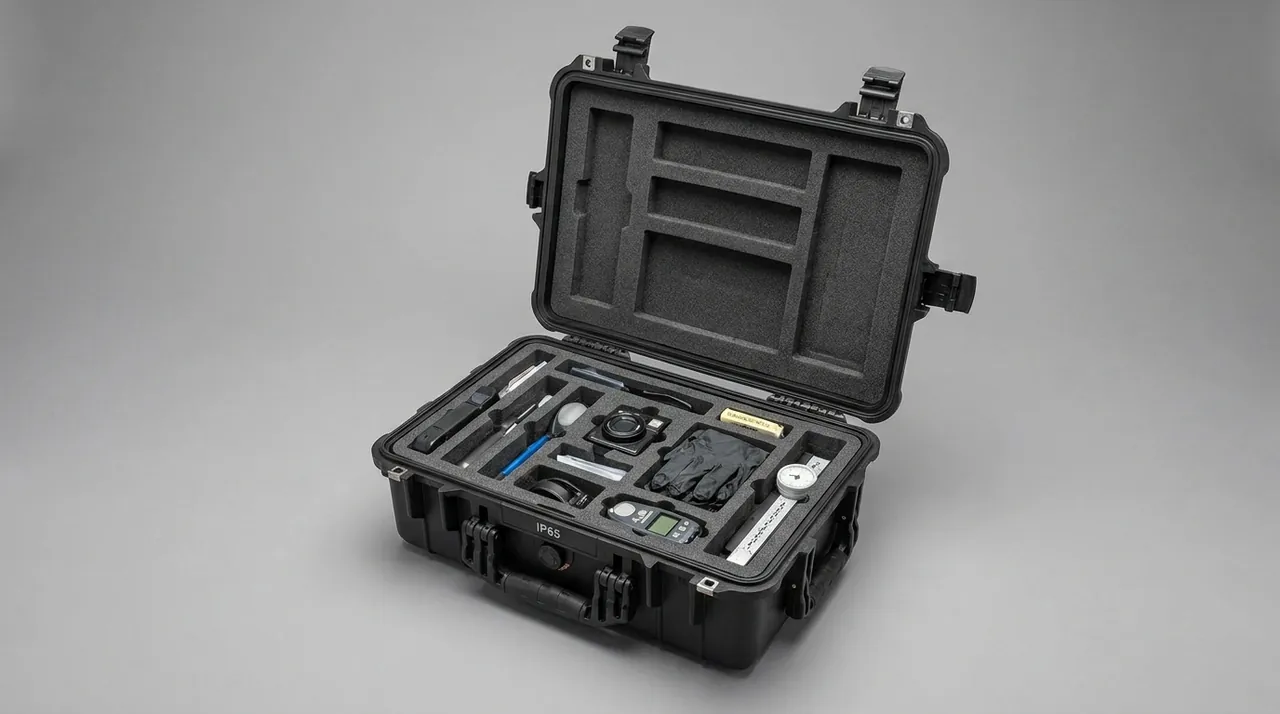
Common parts go in the upper cavities, heavy parts needing special tools go lower, and documents and calibration records go inside the lid. Opening order follows installation order as closely as possible to reduce double handling. For augers and discharge doors assembled on site, locating blocks stay in place until the last moment, so parts keep factory condition even where site conditions are poor.
Site conditions are a further practical point. Many farms and feed plants have no climate-controlled store, and installation often happens outdoors or under a half-open shed where dust and humidity are uncontrolled. We print the tool list inside the lid, with wrench sizes, torque values and a wiring cross-reference, so fitters do not walk back and forth, which also shortens the time parts sit exposed after opening.
Commissioning records matter as much as the packing. No-load zero, loaded output and deviation at each weighing point should be recorded as a baseline. If batching drift appears later, the baseline indicates whether the cause is cell drift, a mechanical loosening or a control parameter problem, instead of a search that starts from nothing.
13. Specifying by Part, Not by Box Size
A practical recommendation for buyers and engineers: list the spare parts and their damage categories first, then decide case size and liner configuration.
The minimum list carries dimensions, mass, accuracy class, metal type, whether a part is calibrated, and whether it contains electrical components. Decisions then follow quickly: which parts need their own cavity, which can share a level, which need axial restraint, and which must be isolated from moisture. Only then choose case material, sealing class, liner material and hardware.
Doing this thoroughly turns a protective case from a box that holds things into a genuine link in the equipment quality chain. JUNZHIJIA, manufactured by Kexin New Materials (Guangdong) Co., Ltd., builds cavity layouts and liner prototypes from a spare-parts list and supplies packaging test reports, helping feed equipment manufacturers cut the hidden losses that occur between dispatch and installation.
14. Frequently Asked Questions
Q: What are the most common causes of an auger deforming during transport? A: The dominant causes are too few support points, leading to self-weight deflection, and direct hard contact between the support and the flight edge. An auger is a long, slender, overhung structure, so if it is supported only at its two ends the middle section sags continuously under its own weight plus vehicle vertical acceleration. After a long road trip, straightness has shifted and the pitch between successive turns is no longer uniform. The second frequent cause is the thin flight edge resting on steel or on a neighbouring part, where a concentrated load rolls the edge over and destroys the leading profile. The third, less obvious cause is resonance: if the first natural frequency of the supported span coincides with a vibration band the truck excites, deflection is multiplied several times over and the auger takes a permanent set. The remedy is to calculate support spacing from the slenderness ratio, cradle both shaft and outer edge in half-round nylon blocks, cut relief pockets where the flight passes, and hold maximum deflection within one thousandth of the span. For multi-section augers, each section gets its own cavity and axial restraint so that one cannot push another.
Q: Why does a load cell show zero drift after transport, sometimes beyond what calibration can fix? A: Zero drift usually means the elastic body entered the plastic region, or the strain-gauge bond layer was damaged. A load cell works through elastic deformation, converting tiny strain into an electrical signal, and a low-capacity unit such as a 100 kg cell can exceed its elastic limit when overloaded by roughly twenty per cent. Once that happens it will not return to its original zero, and calibration can only correct the output curve, not restore structural accuracy. Even without an obvious impact, sustained pressure from a heavy part resting on the cell for hours causes creep, which appears as a slow zero shift that is easy to mistake for a wiring fault. Direct impact is not the main mechanism either; the more common scenario is a gearmotor sharing the same space, moving slightly under vibration and repeatedly squeezing the cell body. This is why cells travel one per cavity with slight pre-compression, kept far from heavy items, so that being pressed or repeatedly squeezed becomes structurally impossible. Each cavity also carries the original calibration data and wiring definition for verification on arrival.
Q: Why does a gearmotor show no problem immediately after a side impact on the output shaft? A: Because the first damage appears in the gear contact pattern and the bearing raceways, not on the outside. A side load increases runout at the shaft end, and the mesh contact area moves from the middle of the tooth flank to the edge, concentrating stress where the gear was never designed to carry it. The motor still runs normally at this stage, and neither noise nor temperature gives the problem away. Only after a few hundred hours of alternating load does the flank develop pitting or spalling, and by then the failure is attributed to the gearbox rather than to transport. The oil seal behaves the same way: once the lip is deformed or grit works past it, sealing capacity drops, but leakage does not begin at once and the unit looks dry on arrival. Protection therefore has to limit side load at the source, using a lined half-round clamp close to the seal, an end plate to control axial movement, and a clear space in the fan direction so that thin blades are never compressed. A useful acceptance test is that the shaft cannot turn once clamped, while leaving no witness mark.
Q: A discharge door looks like a simple flat plate, so why does it need dedicated packaging? A: Flat parts are vulnerable to uneven loading, and the sealing performance of a discharge door depends entirely on flatness. If plates are stacked flat, the lower ones bend slightly under the weight above, and the seal channel distorts with them, so the door can no longer make uniform line contact when it closes. Dust escapes at the highest point of the gap, material absorbs moisture, and batching results begin to drift. The symptom is usually reported as the scale being consistently a little off, and troubleshooting on site frequently starts in the control cabinet, which sends the investigation in the wrong direction and wastes days. The correction is vertical slot storage, so each plate stands in its own plane where bending resistance is greatest, with foam strips holding both sides and a radiused slot entry that cannot cut the seal lip. Loose seals go into a separate cavity to avoid stretching and twisting, and actuators are held at full retraction with a mechanical stop. Adjustable components are marked at factory positions so a fitter can verify nothing moved in transit.
Q: Feed mixers are built for dusty environments, so why does the packaging still emphasise moisture and rust control? A: Dust and moisture are separate threats, and a high dust rating does not mean rust is under control. Feed equipment parts are largely carbon steel, cast iron and blackened machined items, and during storage and sea freight they see day-night temperature swings together with humid air, so machined surfaces flash-rust quickly. Threads, keyways and bores are the worst affected, because they are difficult to coat and hold moisture in their recesses. Corrosion is also irreversible: at best it requires cleaning and recoating, and at worst it changes fits and assembly accuracy, which then shows up as vibration, leakage or a scale that will not hold its zero. The cost is not limited to the part itself, because replacing a corroded component on a working mixer means downtime and lost batches. We therefore combine vapour corrosion inhibitor materials inside sealed cavities, forming a monomolecular protective layer even in recesses that grease cannot reach, with IP67 sealing, a venting valve and per-cavity desiccant. A humidity indicator card gives the user a direct read on whether renewal is due. Dust ingress and moisture ingress are governed by different features of the case, so a box that performs well in a dusty plant is not automatically safe in a humid store.
Q: Why must VCI rust-control material be paired with a sealed case? A: Because vapour corrosion inhibition depends on maintaining a molecular concentration inside a closed space. VCI material releases inhibitor molecules continuously, and those molecules deposit on metal surfaces to form a protective layer covering threads, keyways and recesses that ordinary coatings cannot reach. The efficiency of that process depends on concentration, and concentration depends directly on the air exchange rate of the enclosure. If the case leaks, molecules disperse to the outside air, internal concentration falls, and the protection period shortens markedly, in some cases from about two years to a few months. The two technologies are therefore mutually dependent rather than optional extras: a sealed case without VCI protects against water but not against humidity-driven corrosion, while VCI in an unsealed case is simply consumed and lost. We maintain closure with one-piece moulded gaskets that are never spliced at the corners, calculated latch spacing so the case mouth cannot open locally between latches, and a venting valve that equalises pressure without admitting liquid. Sealing class is then verified by immersion and spray testing rather than assumed from a specification. For long storage we also fit a reusable humidity indicator so the inhibitor charge can be checked at a glance.
Q: What stacking and storage risks are most often overlooked for feed mixer parts cases? A: The most overlooked is creep from long-term stacking. Plastic case walls deform slowly under sustained pressure, and after several months the bulge can press directly on the contents, an effect invisible at the moment of loading and easy to blame on the supplier. Stack height must therefore be derived from long-term load capacity rather than short-term strength, with a recommended layer count marked on the case and pallets or separating boards used underneath. The second risk is rising damp and warehouse humidity: a case sitting directly on the floor keeps its base permanently in a humid layer, and metal parts there corrode first. The third is missing rotation maintenance, because ageing gaskets, loosening latches and damaged liners all reduce protection without any obvious external sign, so a quick post-return inspection with a written record pays for itself. The fourth is handling, since tipping a case onto its side loads the contents in a direction the design never anticipated. Lifting points, fork entry direction and permitted tilt angles should all be explicit in the work instruction, and the case itself should be marked with its centre of gravity so that a lifting sling is placed correctly rather than guessed.
Q: What does compartmentalisation actually deliver compared with simply adding cushioning material? A: The core difference is that compartments convert a random risk into a structurally impossible event. Cushioning material can soften an impact, but it cannot stop a heavy part from drifting slowly under vibration, and that slow drift is exactly what damages precision components. A load cell pressed by a gearmotor for eight hours does not fail loudly; it simply arrives out of tolerance. Compartments cut the load path between parts, because heavy items sit on a dedicated load-bearing beam while precision items are constrained only by their own cavity. The second is diagnostic clarity, since a failure traces to one cavity instead of the whole case. The third is site efficiency: opening order matches installation order, nobody searches through a mixed box, and the chance of fitting the wrong part falls. The trade-off is a larger case, more liner machining and higher unit cost, so we concentrate compartments around load cells and calibrated assemblies. The practical approach is to rank every component by replacement cost and calibration status, then draw compartments around the top of that list. Mid-list parts usually do well with a shared cavity and a separating tray, while structural items such as door plates need only support and anti-scuff protection.
Q: What should an equipment manufacturer look for when selecting a parts-case supplier? A: Four things matter most. First, can the supplier provide a cavity layout and a liner prototype from your parts list, rather than only a catalogue case with loose foam, because that determines whether the scheme actually fits your components. Second, are there real verification data for sealing and corrosion protection, including salt-spray results, immersion or spray test records, and confirmation that a vent valve and humidity indication are fitted. Third, is there engineering capability to check weight and stacking, and to specify a long-term load-bearing layer count together with lifting and fork-entry guidance, since these are where most real-world damage originates. Fourth, is batch consistency controlled through first-article cavity verification, per-case dispatch inspection and archived packing records, so that the thousandth case behaves like the first. It also helps to confirm that the supplier can advise on mode-specific requirements such as container condensation, less-than-container-load handling and air freight pressure differentials. JUNZHIJIA, manufactured by Kexin New Materials (Guangdong) Co., Ltd., provides all of these, with cavity layouts, liner materials and hardware configured from your spare-parts list.
Related Reading: Agricultural machinery parts cases, Bearing and gearbox cases, Weighing and dosing equipment cases, Bulk silo equipment cases, Precision instrument cases, Sensor transport cases, IP67 protective case guide, Heavy-duty case selection, and Warehouse stacking moisture control.