


A differential pressure transmitter leaves the calibration bench with a zero offset of 0.02 percent of full scale. It then travels two thousand kilometres by road, passes two transfer hubs, sits in the open for a day, and is reinstalled on the same pipe run. The zero offset now reads 0.3 percent of full scale, and hysteresis is clearly visible. Nothing is broken. The diaphragm shows no dent, the terminal block is tight, the housing is unmarked. Yet the instrument no longer outputs what it output at the factory. This "intact shell, failed parameters" outcome is the signature loss mode for precision sensor elements, and it is routinely misdiagnosed as a product defect. A sensor is not a structural part. It is an instrument whose real product is a calibration curve, and the curve, not the housing, is what packaging has to preserve.
The objective of sensor transport protection is not "arrive unbroken" but "arrive unchanged" — the case must hold shock acceleration, relative displacement, electrostatic potential and sealed cavity humidity simultaneously inside the window the element datasheet allows. JUNZHIJIA builds sensor transport cases on a four-layer logic: the shell carries stacking and puncture loads, the liner carries energy absorption and location, a conductive or static-dissipative layer carries charge drainage, and the sealing and desiccant system carries humidity and condensation control. Remove any one layer and the loss shows up later as parameter drift measured at incoming inspection.
Table of Contents
- 1. Sensor Transport Failure Modes: From Diaphragm Deformation to Zero Drift
- 2. Sensor Element Classes and Packaging Protection Requirements Matrix
- 3. Case Material Selection and Chemical Compatibility
- 4. Ingress Protection: Where IP65 Ends and IP67 Begins for Sensor Shipments
- 5. Pressure Equalization Valves and Sealed Cavity Humidity Control
- 6. ESD Protection: Surface Resistivity, Conductive Liners and Grounding Paths
- 7. Cushion Liner Stiffness Matching and Thickness Calculation
- 8. Compartmentalization: Process Connections, Diaphragms and Optical Windows
- 9. Vibration and Resonance Avoidance: Natural Frequency and Isolation Design
- 10. Temperature, Humidity, Salt Spray and Condensation Control
- 11. Transport Test Validation: ISTA, GB/T 4857 and ASTM D4169
- 12. Stacking Load, Stack Height and Stack Tier Limits
- 13. Arrival Acceptance Criteria and Unpacking Checklist
- 14. Frequently Asked Questions FAQ
- 15. Conclusion and Related Reading
1. Sensor Transport Failure Modes: From Diaphragm Deformation to Zero Drift
Failures in precision sensor elements are gradual, cumulative and largely invisible. Six mechanisms account for most real transport losses.
Diaphragm plastic residual. The isolating diaphragm of a pressure transmitter is typically 50 to 100 micrometres thick. In transit it sees sustained static load from stacking and transient acceleration from drops and braking. When the uniformly distributed pressure from that acceleration exceeds the elastic margin by fifteen to twenty percent, a plastic residual remains, showing as a zero shift. Oil-filled differential units are worse: repeated impact can draw air into the fill cavity, producing hysteresis and temperature error.
Strain gauge adhesive creep. Load cells work through a strain transfer chain of gauge, adhesive and elastic body. Sustained vibration, especially in the fifteen to thirty hertz wheel-hop band, drives viscoelastic creep in the epoxy layer. Output then drifts by hundreds of microstrain over days, appearing a week into operation rather than on arrival.
MEMS stiction and bond failure. The gap between proof mass and fixed combs in an accelerometer or gyroscope is one to three micrometres. A peak shock above fifteen hundred g can cause stiction, or fatigue a bond wire to failure. Allowable peak shock for a MEMS part is often an order of magnitude tighter than for the structural hardware in the same shipment.
Optical surface damage and axis shift. Window coatings on photoelectric, laser displacement and vision sensors are far softer than steel. Any rubbing against coarse fabric, paper or wood dust leaves scratches that reduce return signal strength. A lens group displaced by micrometres changes the measurement spot position. Neither defect alters electrical parameters, yet both degrade accuracy irreversibly.
Magnetic property change. Inductive and Hall-effect proximity switches depend on core permeability. A strong external field or a severe impact changes permeability and residual magnetism and shortens sensing distance.
Process connection and connector deformation. A scarred sealing face on a G1/2, M20x1.5 or NPT thread leaks once installed. Pins on an M12 A-coded connector sit on roughly one millimetre centres, so lateral shock bends them or cracks the potting. Crimped terminals inside a DIN 43650 valve plug work loose under vibration.
The conclusion is direct: case design must be driven by displacement control and environment control, not by wall thickness.
2. Sensor Element Classes and Packaging Protection Requirements Matrix
Sensitive elements differ so widely that mixing them in one cavity is a leading cause of transit damage. The matrix below is the one JUNZHIJIA uses at concept stage to decide which items must be isolated.
| Element type | Typical construction | Sensitive factors | Shock sensitivity | ESD sensitivity | Humidity sensitivity | Packaging focus |
|---|---|---|---|---|---|---|
| --- | --- | --- | --- | --- | --- | --- |
| Pressure / DP transmitter | 316L diaphragm, oil filled | Diaphragm flatness, fill cavity | Medium-high (20-50 g) | Low | Medium | Diaphragm up, free space above |
| Load cell / force sensor | Strain gauge on elastic body | Adhesive, zero stability | Medium (cumulative) | Low | Low | Limit long vibration, no cantilever load |
| RTD / thermocouple | Sheathed Pt100 probe | Probe bend, insulation resistance | Low | Low | Medium | Axial support, no side load |
| Electromagnetic / vortex flowmeter | Liner plus electrodes | Liner deformation, electrode insulation | Medium | Low | Medium | Flange face covers |
| Photoelectric / laser displacement | Optical window, lens group | Coating, optical axis | High | Medium | Medium-high | Cleanroom cloth plus dedicated slot |
| Proximity / Hall switch | Coil core plus potting | Permeability, potting integrity | Medium | High | Medium | Magnetic shield, dissipative liner |
| MEMS inertial | Proof mass plus bond wires | Stiction, wire fracture | Very high (over 1000 g) | Very high | High | Isolated bay, shield bag, desiccant |
| Transmitter PCB assembly | PCB, ASIC, terminals | ESD, solder fatigue | Medium | Very high (HBM 100-500 V) | High | Metalized shield bag plus dissipative liner |
Both rows marked "very high" go into an isolated bay in every JUNZHIJIA layout, and the liner there must sit in the static-dissipative range. It may not share a cavity with stainless structural parts or aluminium flanges, because charge generated by metal rubbing under vibration injects straight into the component pins.
3. Case Material Selection and Chemical Compatibility
Material selection must satisfy four conditions at once: impact stiffness, controllable surface resistivity, chemical compatibility with cleaning agents and process residues, and creep resistance under long-term stacking.
| Material | Density g/cm3 | Typical wall | Impact | Surface resistivity control | Chemical compatibility | Typical use |
|---|---|---|---|---|---|---|
| --- | --- | --- | --- | --- | --- | --- |
| Copolymer PP, injection | 0.90-0.91 | 3-5 mm | Medium | Requires conductive masterbatch | Acids, alkalis, alcohols, salt spray | Standard sensors, batch rotation |
| ABS, injection | 1.04-1.06 | 3-5 mm | Medium-high | Requires coating or masterbatch | Poor against ketones, esters, strong alkali | Presentation-grade cases |
| Rotomoulded LLDPE | 0.93-0.94 | 6-10 mm | High | Carbon black addition possible | Acids, alkalis, low temperature | Large multi-sensor kits |
| Aluminium-magnesium | 2.70 | 2-3 mm | High | Inherently conductive | Needs anodizing | Severe ESD, shielding duty |
Three details get overlooked. Ordinary ABS has a surface resistivity generally above 10 to the twelfth ohm, so triboelectric charge has no drainage path and can accumulate to several kilovolts; a discharge occurs the moment a component pin touches the wall, which is why ESD-sensitive elements must never rest directly on a plain ABS interior. PP creeps by one to two percent over thirty days at forty degrees Celsius under sustained load, so cases for tall stacks must route load into corner posts through ribs rather than relying on flat panel compression. And an aluminium case forms a galvanic couple with stainless threaded hardware, corroding in salt spray unless the aluminium face is anodized or the thread region is electrically isolated.
On structural and process differences between material systems, see Rotomolded vs Injection Molded Protective Cases; for outdoor service life data see Engineering Plastic Outdoor Cases.
4. Ingress Protection: Where IP65 Ends and IP67 Begins for Sensor Shipments
IP ratings are defined in IEC 60529 and the equivalent GB/T 4208. The first digit covers solid objects, the second covers liquid.
| Rating | Dust | Water | Transport scenario | Typical sensor configuration |
|---|---|---|---|---|
| --- | --- | --- | --- | --- |
| IP54 | Level 5 | Splash | In-plant transfer, short urban moves | Bag plus carton is sufficient |
| IP65 | Dust tight | Water jets | Domestic road transport, hub transfers, rain-exposed handling | Rigid case, single seal |
| IP66 | Dust tight | Powerful jets | High-pressure washdown zones, refrigerated transfer | Rigid case, double seal, drainage channel |
| IP67 | Dust tight | Short immersion | Sea freight, intermodal, open storage, container floor | Rigid case, double seal, pressure valve |
One boundary must be stated plainly: an IP rating covers only water and dust, not vapour, chemical mist or condensation. Relative humidity inside a sea container can hold above eighty-five percent for weeks, and the daily temperature swing makes the case wall alternately the cold condensing surface. A well-sealed case is more dangerous here, because moisture closed in at packing time cannot escape and must be absorbed by desiccant. An IP67 case on a long sea route therefore needs desiccant and a humidity indicator card as standard. The layered approach is described further in System Level IP67 Design.
For seal verification, a negative pressure hold test is preferred: evacuate to minus twenty kilopascals, hold five minutes, accept a decay of no more than one kilopascal. It is more sensitive than immersion and carries no water into the seal groove. Where third-party judgement is required, the evidence checklist in Verifying IP67 Certification applies.
5. Pressure Equalization Valves and Sealed Cavity Humidity Control
A sealed case develops a pressure difference against ambient whenever temperature or altitude changes. At constant volume the differential is proportional to the difference in absolute temperature: falling from twenty to minus twenty degrees Celsius, from 293 to 253 kelvin, produces about 13.7 percent of the initial absolute pressure, roughly fourteen kilopascals. An air cargo hold pressurised to a 75 kilopascal equivalent produces twenty-five to thirty kilopascals.
Three consequences follow. The seal ring is pressed into or blown out of its groove, making the case hard to open without destructive force. The wall deflects inward, squeezing the liner and adding a uniform load onto the diaphragm. And repeated pressure cycles accelerate compression set in the seal.
A waterproof-breathable equalization valve with an ePTFE membrane resolves the conflict. Typical ePTFE pore size is 0.1 to 1 micrometre, far below the roughly twenty micrometre minimum of a liquid droplet, so liquid water cannot pass, while a water vapour molecule at about 0.0004 micrometre migrates freely. Airflow is typically fifty to three hundred millilitres per minute per square centimetre per bar.
Two rules are commonly violated. The valve body must be mounted on a side wall section that does not pond water, never on a recessed top face or the underside, where it becomes a direct ingress path under immersion. And because a vent lets vapour migrate in both directions, desiccant must never be loose in the case. The correct arrangement is dual: the outer rigid case breathes through the valve, while an inner metalized or foil barrier bag seals the element together with the desiccant into a low-humidity micro-environment.
For assemblies that must stay dry for months, place silica gel or type 4A molecular sieve inside the barrier bag and add a segmented humidity indicator card, typically marked at five, ten and fifteen percent, or ten, twenty and thirty percent. A reading above twenty percent at arrival means the assembly should be re-dried before installation.
6. ESD Protection: Surface Resistivity, Conductive Liners and Grounding Paths
Electrostatic discharge damage to sensor electronics has a delayed-exposure signature: an ASIC input stage weakened by ESD can pass factory test perfectly and fail months after installation as leakage current rises. Relevant standards include IEC 61340-5-1 and ANSI/ESD S541.
| Surface resistivity | Classification | Liner examples | Guidance |
|---|---|---|---|
| --- | --- | --- | --- |
| 10^2-10^5 ohm | Conductive | Metalized fabric, nickel-coated cloth | Shield bags, shorting caps; not in direct contact |
| 10^5-10^11 ohm | Static dissipative | Carbon-filled EVA, conductive PE foam | Recommended direct contact layer |
| 10^11-10^12 ohm | Antistatic | Antistatic-treated PE | Short-term rotation only, performance decays |
| Above 10^12 ohm | Insulating | Plain ABS, plain EPE, PVC | Prohibited against ESD-sensitive parts |
The system has four layers. The contact layer seats the element in carbon-filled EVA or static-dissipative PE foam at a controlled surface resistivity of 10^6 to 10^9 ohm, slow enough to drain charge but not so conductive that it delivers a high-current discharge. The barrier layer wraps the element in a metalized shield bag below 10^2 ohm, isolating external fields and creating a low-humidity micro-climate. The pin layer fits conductive PE caps on M12 and DIN 43650 connectors so all pins are shorted. The ground layer requires the operator to equalise potential with the case before opening, and the case to be bonded to ground where the material is conductive. Unpacking directly on synthetic carpet or a plastic bench top is not acceptable.
7. Cushion Liner Stiffness Matching and Thickness Calculation
Liner thickness is not a matter of packing generously. It is determined jointly by drop height and the acceleration the element permits. A simplified energy model that neglects material hysteresis gives:
delta = 2 H / a_max
where delta is the effective compression travel of the cushion in metres, H is the drop height in metres, and a_max is the permitted acceleration as a multiple of g. For a drop height of 0.8 metre and a permitted acceleration of 40 g, delta equals 2 times 0.8 divided by 40, or 0.04 metre, a forty millimetre compression travel. Allowing a factor of 1.3 to 1.5 for material fatigue and temperature effects on stiffness, the liner should be fifty-two to sixty millimetres thick.
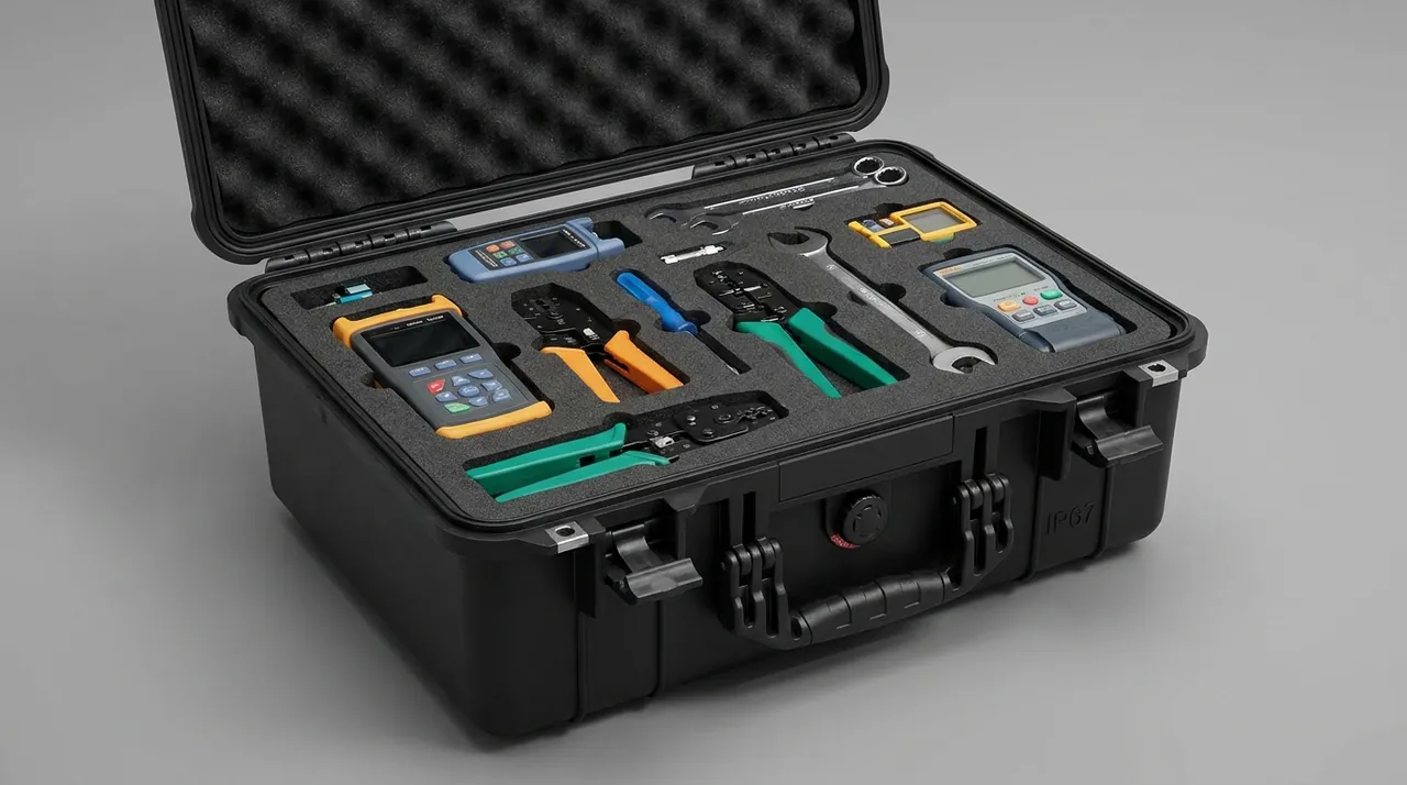
| Material | Density kg/m3 | Stress at 25% compression | Resilience | Character | Role in a sensor case |
|---|---|---|---|---|---|
| --- | --- | --- | --- | --- | --- |
| EPE | 25-35 | 0.10-0.18 MPa | Above 90% | Stable after repeated impact, low cost | Outer energy absorbing layer |
| EVA | 40-80 | 0.25-0.50 MPa | Above 95% | CNC machinable, tight tolerances | Inner locating layer, dividers |
| IXPE | 30-60 | 0.15-0.35 MPa | Above 90% | Available as thin as 3-10 mm | Gap filling, facing |
| PU foam | 25-45 | 0.08-0.20 MPa | Above 90% | Soft, conforms well | Irregular surfaces, optics wrap |
| Hybrid build | - | - | - | Soft outside, firm inside | Combines absorption and location |
One failure point is widely ignored: the fit clearance between liner and element must be under one millimetre. At three millimetres of clearance the element free-travels three millimetres before striking the liner, which is equivalent to raising the drop height and can raise measured shock acceleration by sixty to one hundred percent. That is why a case packed full of foam can still protect nothing. The problem is not foam thickness, it is fit accuracy.
8. Compartmentalization: Process Connections, Diaphragms and Optical Windows
The most fragile surfaces on a pressure transmitter are not the housing but three faces: the diaphragm face, the threaded sealing face and the connector terminal face. How those three are oriented and supported decides whether the packing scheme is acceptable.
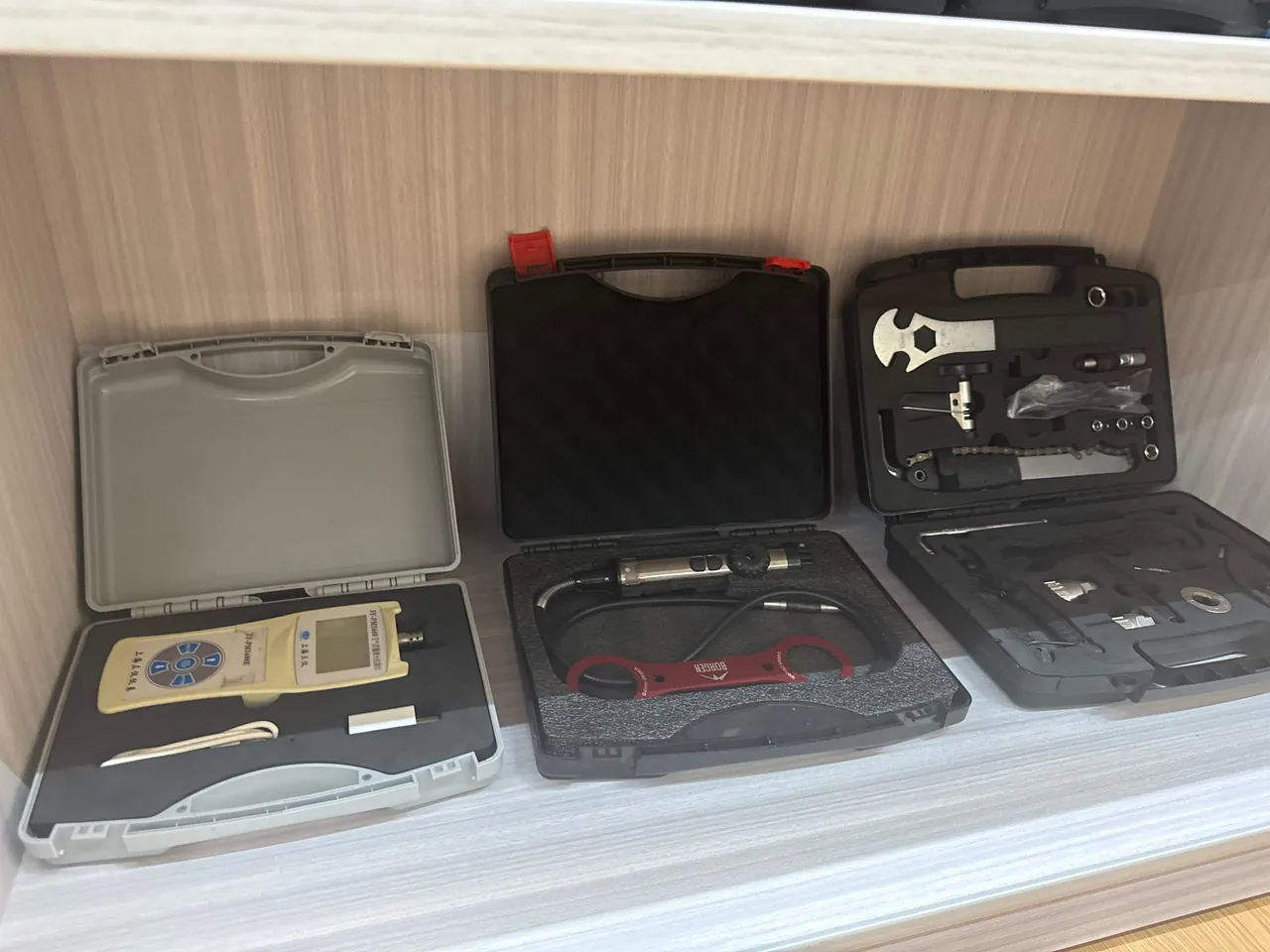
Four rules govern compartmentalization.
- Diaphragms and optical windows always face up, with ten to fifteen millimetres of clear space directly above. No divider, retainer bar or rigid part may intrude. Where vertical packing is unavoidable, add a compliant stop limiting axial movement to 0.5 millimetre.
- Process connections are located by counterbore plus nylon bushing so the threaded section floats rather than pressing into foam. A G1/2 or M20x1.5 sealing cone held under foam compression over a long route will weep once installed.
- Sensitive classes never share a cavity. MEMS inertial parts and optical parts get their own cells. Metal flanges, wrenches and clamps travel in a separate accessory cavity and never alongside elements.
- Removable dividers need a top retainer bar. Many transit incidents happen not at impact but when the case tips and a divider falls over, letting elements collide inside the cavity.
| Location | Locating method | Permitted movement | Prohibited |
|---|---|---|---|
| --- | --- | --- | --- |
| Diaphragm / measuring face | Face up, clear space above | 0.5 mm axial | Any rigid part above |
| Threaded connection | Counterbore plus nylon bushing | 0.5 mm | Thread pressed into foam |
| Optical window | Cleanroom cloth, PE bag, EVA slot | 1 mm | Contact with metal parts |
| Connector | Conductive cap, dedicated recess | 1 mm | Load through pins |
| Transmitter PCB | Dissipative liner plus retainer | 1 mm | Unsupported board edge |
| Accessories | Separate accessory cavity | Unrestricted | Sharing a cavity with elements |
Where element variants change frequently, a removable divider system is preferable. Structure options are compared in Removable Divider Systems and Dividers versus Foam.
9. Vibration and Resonance Avoidance: Natural Frequency and Isolation Design
Transport vibration energy concentrates at low frequency. Road transport splits into roughly three bands: three to eight hertz from suspension movement, fifteen to thirty hertz from tyre and road coupling, and twenty to one hundred hertz from the powertrain. Air cargo random vibration concentrates between ten and one hundred hertz. Sea transport is dominated by one to twenty hertz wave excitation with propeller frequencies at twenty to sixty hertz.
The objective is to avoid resonance. In the mass-spring system formed by case, liner and element, the first natural frequency should either sit at least a factor of two from the dominant excitation frequency, or fall in a band where excitation energy is low. Where separation is impossible, only damping dissipates the energy, and EVA with a loss factor of about 0.10 to 0.25 is a practical damping layer.
A real trade-off exists. A softer liner isolates vibration better but allows greater displacement and risks over-travel in a drop. A firmer liner controls displacement but raises transmissibility, and long-term vibration then accelerates adhesive creep and loosens terminals. JUNZHIJIA resolves this with a two-stiffness build: an outer layer of roughly twenty-five kilogram per cubic metre EPE absorbs impact energy, an inner layer of fifty to sixty kilogram per cubic metre EVA carries location and stiffness, and the two are not bonded, so a small relative slide adds frictional damping.
For long sea routes, external restraint should be added: nylon webbing with a breaking strength of at least one kilonewton lashing the case to the pallet reduces whole-case bounce. Fastener loosening is handled with medium-strength threadlocker or spring washers, consistent with the approach in Shockproof Cases for Precision Tools.
10. Temperature, Humidity, Salt Spray and Condensation Control
Moisture is the least visible and least reversible influence in sensor transport. Oil fill cavities, ASIC packages and insulator surfaces can all absorb moisture and shift electrical behaviour.
Desiccant quantity can be estimated from the equilibrium uptake of silica gel, roughly twenty percent of its own mass at twenty-five degrees Celsius and forty percent relative humidity, combined with internal volume, transit duration and target humidity:
| Internal volume m3 | Road, up to 7 days | Sea, 30 days | Tropical, 45 days (4A sieve) |
|---|---|---|---|
| --- | --- | --- | --- |
| 0.02 | 15 g | 25 g | 20 g |
| 0.05 | 35 g | 60 g | 45 g |
| 0.10 | 70 g | 120 g | 90 g |
| 0.20 | 130 g | 230 g | 170 g |
Type 4A molecular sieve outperforms silica gel markedly in the low-humidity range and can be used at sixty to seventy percent of the silica gel mass, which suits MEMS and optical elements with tight humidity limits.
Salt spray control follows the neutral salt spray test in GB/T 10125, usually judged over forty-eight to ninety-six hours. The three corrosion hot spots on a sensor case are the hinge pin, the latch spring and the handle pin, where 316 stainless should be specified first. Salt spray testing ranks competing schemes against each other; it does not project field life and does not support any certification claim.
Condensation is controlled by three measures. Avoid large metal surfaces directly adjacent to plastic surfaces inside the case, because the difference in heat capacity and conductivity makes the metal face the first condensing surface during a rapid temperature change. Leave two to three millimetres of vent channel in the liner so moisture is absorbed evenly by desiccant rather than trapped in a local cavity. And allow the case to equalise with ambient for two to four hours before opening.
11. Transport Test Validation: ISTA, GB/T 4857 and ASTM D4169
Packaging reliability has to be demonstrated by test, not inferred from calculation. The test system for sensor cases normally runs at two levels: whole-case and element.
| Standard | Level | Main procedures | Sensor acceptance criteria |
|---|---|---|---|
| --- | --- | --- | --- |
| ISTA 1A / 2A | Whole case, up to 68 kg | Drop, random vibration, stack | Zero drift at or below 0.1% FS |
| ISTA 3A | Whole case, parcel | Drop, random vibration, compression | Insulation resistance at or above 100 megohm |
| GB/T 4857.5 / .7 / .3 | Whole case, domestic | Drop, sinusoidal vibration, stack | No plastic residual on diaphragm, threads intact |
| ASTM D4169 DC13 | Whole case, air plus road | Low pressure, vibration, drop | No moisture ingress, differential within limit |
| IEC 60068-2-27 Eb | Element | Half-sine shock, 15 g, 11 ms | No structural displacement, no functional loss |
| IEC 60068-2-64 Fh | Element | Random vibration, 10-500 Hz | Output drift at or below 0.05% FS |
| IEC 60529 | Whole case | IP dust and water | Negative pressure hold, decay at or below 1 kPa |
Two conclusions must be kept apart. A passed whole-case test only says the combination of case, liner and element protects the element under that spectrum. A passed element test only says the element tolerates that magnitude of direct excitation. Neither substitutes for the other. A complete validation report contains both whole-case data and post-test element parameter measurements.
12. Stacking Load, Stack Height and Stack Tier Limits
Stacking is the dominant sustained load in transport and storage, and the main reason diaphragms sit under compression for weeks. The load on the bottom case is estimated as:
P = m (n - 1) k
where P is the load on the bottom case in kilograms, m is the gross mass of one case, n is the number of tiers, and k is a dynamic factor normally taken as 1.5 to 2.0. For a twenty-five kilogram case stacked five high with k at 1.8, the bottom case carries 25 times 4 times 1.8, or 180 kilograms. If the footprint is 0.12 square metre, the top face pressure is about 14.7 kilopascals, at the level of the stress a medium-density EPE sees at twenty-five percent compression. If the liner takes that load directly instead of routing it into corner posts, the elements stay under compression for the whole journey. The case must therefore direct stacking load through ribs into the corner posts, and the liner should provide an unloading zone so the cavity above an element does not line up with a lid rib.
Long-term creep also has to be budgeted. PP creeps by roughly one to two percent over thirty days at forty degrees Celsius, and a sea container can reach sixty degrees Celsius, where creep increases noticeably. A practical approach is to set the actual stacking limit at eighty percent of the designed tier count and to mark the maximum stack tiers and gross mass on the case.
Package handling marks follow GB/T 191 and GB/T 13384, covering this way up, keep dry, do not roll, centre of gravity and stacking tier limit. For palletised sea freight, keep total pallet height at or below 1.5 metres.
13. Arrival Acceptance Criteria and Unpacking Checklist
Arrival inspection is the last gate before transport damage becomes a production problem. Because sensor damage is usually progressive, inspection must include parameter re-measurement and cannot stop at visual checks.
| Check item | Method | Criterion | Action on failure |
|---|---|---|---|
| --- | --- | --- | --- |
| Case shell | Visual, open and close | No puncture, no crack, normal operation | Record and photograph, quarantine |
| Water traces | Visual plus absorbent paper | No seepage mark, no salt bloom | Stop unpacking and isolate |
| Humidity card | Read indicator | At or below 20% | Re-dry and recheck above 20% |
| Liner displacement | Feeler gauge, witness marks | No free travel mark over 1 mm | Re-check liner fit |
| Diaphragm / optics | Visual plus loupe | No dent, scratch or coating loss | Send for metrology |
| Threads and connectors | Visual plus go gauge | No scar, no pin offset | Replace part |
| Insulation resistance | 500 VDC megohmmeter | At or above 100 megohm | Judge as wet or damaged |
| Zero and span | Traceable signal source | Drift at or below 0.1% FS, repeatability at or below 0.05% | Recalibrate or reject |
| Shipping documents | Checklist review | Packing list, humidity record, test report complete | Complete the file |
Take a matched pair of photographs at packing and at unpacking to create a traceable packaging record. Only then can a dispute establish whether damage occurred in transit or at assembly.
14. Frequently Asked Questions FAQ
Q: Why does sensor transport protection focus on zero drift rather than on a broken housing?
A: Because the value of a sensor element sits in its calibrated transfer curve, not in the integrity of its enclosure. A broken housing is an explicit failure recognised the moment the case is opened, and it can go straight into a claim. Zero drift is a latent failure: the part looks perfect and electrical continuity is normal, yet zero, span, hysteresis and repeatability have moved outside the factory tolerance, and only a parameter re-test reveals it. More importantly, the load that causes drift is far lower than the load that breaks a housing. A diaphragm can take a plastic residual at only twenty to fifty g, while the same shock leaves the shell unmarked. Case design must therefore work backwards from the element permitted acceleration to derive liner thickness and stiffness, rather than forwards from shell puncture resistance. In practice the purchase specification should state the permitted acceleration per element class, and the liner drawing should be approved against that number rather than against a general fragility claim.
Q: Why does an IP67 sensor case still need an open equalization valve during air freight?
A: An air cargo hold typically holds an equivalent pressure of about seventy-five kilopascals in cruise, while the case closes at close to one hundred and one kilopascals at packing, so the differential reaches twenty-five to thirty kilopascals. At that magnitude the seal ring is pressed into its groove, the wall deflects inward, the liner is squeezed and the diaphragm receives an added uniform load. Repeated pressure cycles also accelerate compression set in the seal and shorten the reuse life of the case. A waterproof-breathable equalization valve using an ePTFE membrane with pores of 0.1 to 1 micrometre passes gas while blocking liquid water, holding the differential within about one kilopascal. The important consequence is that the vent allows vapour to migrate both ways, so a metalized barrier bag must be added inside, sealing the element together with desiccant. The dual structure, breathing outside and sealed inside, is the only configuration that satisfies both pressure and humidity requirements at once, which is why the vent and the bag must always be specified together.
Q: Is a thicker cushion liner always safer?
A: No. Liner thickness should follow the relationship delta equals two H divided by a_max, where H is drop height and a_max is the permitted acceleration in multiples of g. That calculation yields a required compression travel, not a rule that more foam is better. An over-thick liner creates two new problems. It consumes internal volume, so elements must sit closer together and compartmentalization may become impossible. And a softer liner lets elements travel further under vibration, so they can rub repeatedly against dividers, retainer bars or the case wall and suffer abrasion damage. The decisive variable is actually fit accuracy: the clearance between liner and element must stay below one millimetre. Above that, the element free-travels before it strikes the liner, which is equivalent to increasing the drop height, and measured shock acceleration can rise by sixty to one hundred percent. Thickness without fit control buys almost nothing, because free travel adds energy rather than absorbing it into the cushion.
Q: Why can an ESD-sensitive sensor not rest on a plain ABS interior?
A: Plain ABS typically has a surface resistivity above 10 to the twelfth ohm, which makes it an insulator. Under transport vibration the element rubs against that wall, generating and accumulating triboelectric charge with no drainage path. The interior can reach several kilovolts, and as soon as a component pin or a board edge touches the wall, a discharge occurs. The signature of ESD damage is delayed exposure: a damaged ASIC input stage can pass factory test perfectly and fail months after installation as leakage current rises, producing a field failure whose responsibility is nearly impossible to assign. The correct arrangement uses a static-dissipative contact layer with a surface resistivity between 10^5 and 10^11 ohm, combined with a metalized shield bag and conductive pin caps. Operators must also equalise potential with the case before opening it, because the final discharge of the sequence is often delivered by the person unpacking the shipment. A wrist strap and a grounded bench mat cost little compared with a field failure that cannot be reproduced.
Q: Why should desiccant never be left loose inside a sealed case?
A: Because a sealed case is not actually sealed. To relieve the differential pressure created by temperature and altitude changes, the case carries a waterproof-breathable equalization valve, and that valve passes water vapour in both directions. If desiccant is loose in the case, it continuously absorbs vapour migrating in from outside, exhausts its adsorption capacity early, and is already spent when it is finally needed. The correct architecture separates the functions. The outer rigid case vents through the valve to equalise pressure. An inner metalized or foil barrier bag is heat sealed around the element together with the desiccant, creating a genuinely low-humidity micro-environment that the valve cannot reach. A segmented humidity indicator card goes inside the bag, and a reading above twenty percent at arrival means the assembly should be re-dried before use. Loose desiccant in the outer cavity is among the most common and most easily corrected packaging errors, and the fix costs almost nothing beyond moving the bag inside.
Q: Can different sensor types share a single cavity?
A: It is not advisable, for three separate reasons. The first is sensitivity class: MEMS inertial parts and optical assemblies permit an order of magnitude less acceleration than stainless structural parts, so a shared cavity forces the liner to be designed for the tightest element, over-packaging everything else at avoidable cost. The second is material interaction: metal flanges, wrenches and clamps rub against elements under vibration, acting as both a mechanical damage source and a triboelectric charge source. The third is magnetic behaviour, because unshielded permanent magnets alter the core state of inductive and Hall-effect switches. The JUNZHIJIA standard is to grade elements into three classes. Class one goes into an isolated bay with a static-dissipative liner and a shield bag, class two may be compartmentalized by variant, and class three accessories travel in a dedicated accessory cavity, separated from every element. Grading is recorded on the packing specification so a later accessory change cannot silently break the arrangement, and it is reviewed at every product revision.
Q: If a case passes ISTA testing, are element-level tests unnecessary?
A: They are not interchangeable. A whole-case test evaluates the combined system of case, liner and element and produces the conclusion that the combination protects the element under that spectrum; it says nothing about how much direct excitation the element itself tolerates. An element-level test such as IEC 60068-2-27 half-sine shock or IEC 60068-2-64 random vibration evaluates the component and produces the conclusion that the element survives that magnitude of direct excitation, but it says nothing about how the case behaves under stacking, air cargo low pressure, or repeated transfer dynamic loads. Complete validation requires both data sets, and every test round should be followed by re-measurement of zero, span, hysteresis and insulation resistance, so that the criterion is upgraded from no structural damage to no parameter change. That upgrade matters commercially, because only a parameter-based criterion gives both parties a defensible basis for accepting or rejecting a delivery batch, and both reports belong together in the same batch file for that shipment.
Q: Why is a two-stiffness liner recommended for sea freight batches?
A: Because sea transport presents two conflicting load families at once. The low-frequency band, one to twenty hertz of wave excitation, favours a soft liner to isolate vibration and avoid the long-term excitation that accelerates strain gauge adhesive creep and loosens terminals. Handling and stacking shocks favour a firm liner to limit displacement so elements cannot strike the cavity wall. A single-stiffness liner can only compromise between the two and will sacrifice one. The two-stiffness build separates the functions instead: an outer layer of roughly twenty-five kilogram per cubic metre EPE absorbs impact energy and isolates vibration, while an inner layer of fifty to sixty kilogram per cubic metre EVA carries location and stiffness. The layers are not bonded, so a small relative slide provides additional frictional damping. The result is a system whose first natural frequency stays clear of the dominant excitation band while element displacement remains under one millimetre.
15. Conclusion and Related Reading
Sensor transport protection is about moving a precision instrument from the calibration bench to the field without changing what it measures. JUNZHIJIA backs that goal with custom liner engineering, OEM and ODM programmes, and full shipping documentation.
Related Reading