

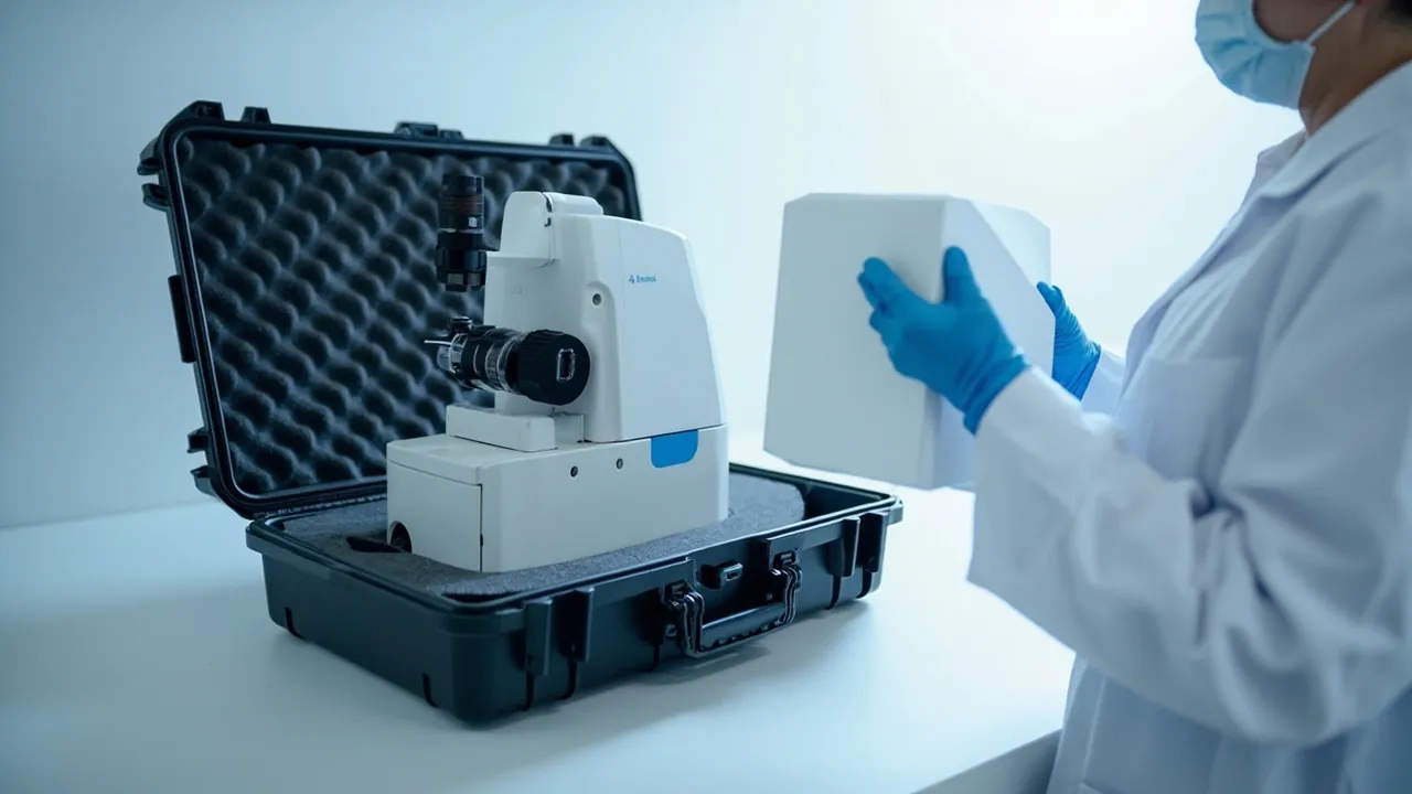
A spectrometer is a classic three-in-one analytical instrument combining precision optics, precision electronics and precision mechanics, and its transport protection problem is this: the optical bench, the grating and the detector each tolerate a given stress completely differently, yet they are coupled to one another through a single rigid beam path. The optical bench demands structural rigidity and dimensional stability, since any bending or twisting changes the beam path geometry. The grating and dispersion elements demand angular accuracy and surface cleanliness, since a tiny change in angle shifts the wavelength calibration. The detector demands fixed position, freedom from electrostatic damage and reliable thermal management. The correct selection logic for a spectrometer case is therefore integral rigid support, isolated beam path, dedicated detector protection, and humidity and cleanliness control throughout, not treating the instrument as a fragile box.
The practical pain points cluster in five areas. The first is optical misalignment caused by vibration and shock. Once the optical bench flexes slightly, or the grating turret rotates by a tiny angle, wavelength accuracy and resolution fall. This degradation is often only discovered during the first calibration after arrival, by which time the damage has already occurred. The second is loss of cleanliness control. The internal optical surfaces of a spectrometer, including mirrors, grating rulings, lenses and optical windows, are extremely particle-sensitive, and a micrometre-scale particle on an optical surface produces noticeable stray light and false peaks. The third is humidity and condensation. Some spectrometers contain hygroscopic materials, such as certain infrared optical crystals and halide windows, where moisture reduces transmission and fogs the surface, while condensation in a sea freight container is worse still. The fourth is electrostatic and thermal damage to detectors. CCD and CMOS devices and photomultiplier tubes are sensitive to electrostatic discharge, and some detectors operate at low temperature, so poor temperature management in transport and storage causes performance drift. The fifth is damage to gas and liquid interfaces. Spectrometers usually carry argon purge ports, sample gas lines, cooling water circuits or vacuum interfaces, and impact deformation of these fittings causes leakage and contamination.
This article works through the protection logic in the order of optical bench, grating, detector, sample interface, cleanliness and humidity control, isolation and sealing, and testing and acceptance. It provides a spectrometer type comparison table, an optical and detection component protection table, cleanliness and humidity control points, sealing class recommendations, a transport test plan and a specification selection table. JUNZHJIA serves spectrometer manufacturers, analytical instrument distributors, third-party testing laboratories and instrument rental services with high-rigidity case design, clean optical cavity inserts, ESD-safe detector cavities, model-matched isolation and humidity control, and OEM/ODM volume delivery, manufactured and shipped worldwide by Kexin New Materials (Guangdong) Co., Ltd.
Table of Contents
- 1. Why Spectrometers Need Purpose-Built Cases
- 2. Risk Profile: Failure Modes of Optical Bench, Grating and Detector
- 3. Spectrometer Types and Their Differing Protection Needs
- 4. Optical Bench Protection: Alignment Stability and Structural Rigidity
- 5. Protecting Gratings and Dispersion Elements
- 6. Detector Protection: CCD, CMOS and Photomultiplier Tubes
- 7. Sample Interfaces, Slits, Gas and Liquid Lines
- 8. Cleanliness and Particle Control
- 9. Humidity, Condensation and Purge Gas
- 10. Vibration Isolation and Cushioning: Graded Design
- 11. Sealing Class, Pressure Equalisation and Cable Penetrations
- 12. Custom Inserts and Cavity Schemes
- 13. Transport Testing: ISTA, GB/T 4857, ASTM D4169 and the MIL-STD-810H Note
- 14. Procurement Acceptance, AQL, Selection Table and Export Recalibration
- Frequently Asked Questions
- Conclusion & Related Reading
1. Why Spectrometers Need Purpose-Built Cases
The starting point for understanding spectrometer transport protection is the fact that one rigid beam path links three component classes of quite different sensitivity.
The optical bench is the geometric datum of the whole instrument. The bench, sometimes called the optical base or optical platform, is usually a precision-machined metal plate carrying the entrance slit, collimating mirror, grating turret, focusing mirror and detector. Every element position is set by optical design, and the angular and distance relationships between them must hold within small tolerances. The rigidity of the bench determines whether that geometry survives vibration and shock. If the bench bends in transit, the elements mounted on it shift as a group; if it twists, the symmetry of the beam path is broken. The core of optical bench protection is therefore limiting the bending and torsional moments applied to the bench, not simply cushioning it.
The grating and dispersion elements are the source of wavelength accuracy. A grating disperses polychromatic light by wavelength, with ruling densities typically from several hundred to several thousand lines per millimetre. Wavelength accuracy depends on the angular position of the grating: for every tiny rotation, the output wavelength shifts correspondingly. The grating and its turret mechanism are therefore highly sensitive to vibration, shock and temperature change, and anything that changes the grating angle appears directly as a wavelength error.
The detector is the end of the signal chain and the most electronic part. CCD, CMOS, photomultiplier tube, thermocouple, InGaAs and mercury cadmium telluride detectors differ greatly in protection requirements. Silicon CCD and CMOS devices are static-sensitive, and electrostatic discharge can permanently kill pixels. Photomultiplier tubes are vacuum tube devices vulnerable to mechanical shock, and some types are magnetic-field sensitive. Infrared detectors such as MCT usually operate cold and are very sensitive to thermal cycling and condensation. Thermal detectors are sensitive to mechanical stress. Detector protection must therefore be designed by type.
Coupling creates a special constraint. Because the optical bench, grating and detector are linked by one beam path, protecting only one link is useless: even with excellent detector protection, a bent optical bench shifts the spot position and the detector no longer receives light in the right place. A spectrometer case design must therefore be system level: integral rigid support as the foundation, beam path isolation as the method, dedicated detector cavities as a complement, and humidity and cleanliness control as the environmental guarantee.
Post-arrival recalibration cost is an economic factor that must be counted. A spectrometer normally needs wavelength and intensity verification after transport, and the worse the misalignment the greater the recalibration effort, potentially requiring optical component replacement or a return to the factory. Counting recalibration and downtime cost into the packaging decision is the most frequently overlooked judgement in procurement.
In summary, the core requirements for a spectrometer case are high-rigidity integral support, beam path isolation, detector protection by type, and humidity and cleanliness control throughout. A general selection framework is in the Instrument case selection guide.
2. Risk Profile: Failure Modes of Optical Bench, Grating and Detector
The spectrometer logistics chain is typically: instrument manufacturer, distributor or regional office, then user laboratory, via long-distance road, rail, sea or air freight, with some scenarios also involving on-site testing by a third-party laboratory and rental turnover.
| Chain stage | Dominant stress | Typical consequence | Protection focus |
|---|---|---|---|
| --- | --- | --- | --- |
| Factory dispatch | Shock, sustained vibration, temperature swing | Bench micro-deformation, grating angle shift | Integral rigid support, attitude fixation, isolation |
| Distributor warehousing | Long-term static load, humidity, temperature swing | Optical surface moisture, detector drift | Humidity control, desiccant, temperature stability |
| Long-haul road and rail | Low-frequency vibration, random shock | Beam path misalignment, fastener loosening, cable fatigue | Low-frequency isolation, anti-loosening, cable limits |
| Sea and air freight | High humidity, heat, condensation, low pressure, repeated handling | Crystal moisture, condensation, seal failure, case compression | IP67 plus pressure equalisation plus desiccant |
| Laboratory installation and recalibration | Handling, unpacking, abrupt environment change | Optical contamination, condensation, extra recalibration work | Clean unpacking, temperature equalisation, staged unwrapping |
Optical bench failure takes the form of micro-deformation. Visible bending or fracture is rare; what is far more common is micron-scale bending, twisting or residual local stress. The consequence is that mirror group relative positions shift slightly, the spot moves on the detector, spectral resolution falls and wavelength calibration acquires a systematic error. This failure cannot be found by a visual inspection on arrival and can only be identified by comparing recalibration data.
Grating failure takes the form of angular shift. A grating is normally mounted on a precision turret or swing arm located by a worm gear, harmonic drive or direct-drive motor. Vibration in transit changes the preload state of the mechanism, and shock can cause micro-damage to gear flanks or brinelling of bearing races. It shows up as degraded wavelength repeatability, the same wavelength appearing at different positions across measurements, and small jumps during scanning.
Detector failure modes diverge by type. For CCD and CMOS, electrostatic discharge causes pixel or readout circuit failure, since handling friction in a dry environment alone can generate enough energy; mechanical shock cracks packages or fatigues solder joints; moisture condenses inside the package. For photomultiplier tubes, the vacuum envelope is shock-sensitive because relative movement of internal electrodes changes gain; the high-voltage section is moisture-sensitive; and some types are magnetic-field sensitive, drifting in gain near strong magnetic equipment. For infrared detectors, thermal cycling causes thermal stress, condensation and frost form, and the long-term stability of some materials depends on humidity. For thermal and pyroelectric detectors, mechanical stress changes the response.
Sample interfaces and slits are easily overlooked but the consequences are direct. Entrance slit width is typically between micrometres and tens of micrometres, and any damage to the slit edges changes the effective bandwidth and throughput. Argon purge ports, sample gas fittings and cooling water fittings leak and contaminate once deformed, and a scratched vacuum sealing face cannot be recovered by tightening.
Loss of cleanliness control is a hidden but lethal risk. Once internal optical surfaces are contaminated by particles, the result is increased stray light, false peaks and baseline drift. What characterises this failure is that no mechanical inspection reveals it; it surfaces only when spectral quality falls, by which point the stage at which contamination occurred is usually impossible to determine.
3. Spectrometer Types and Their Differing Protection Needs
Different spectrometer types differ significantly in protection requirements and must be designed separately.
Spark optical emission spectrometers (OES) analyse metal composition and are usually large and heavy, often in the hundreds of kilograms, containing an electrode stand, excitation table, grating optics and multi-channel detectors. Their characteristics are high machine weight, demanding on case load capacity and lifting; an open excitation table and electrode stand vulnerable to contamination and impact; an argon purge system with gas fittings prone to leakage; and an optical system often under vacuum or inert gas, vulnerable to seal failure under vibration. Protection focus: heavy-duty load bearing, integral isolation, gas fitting protection and optical chamber attitude fixation.
ICP spectrometers, including ICP-OES and ICP-MS, contain a radiofrequency generator, plasma torch, sample introduction system and optical detection system. Their characteristics are quartz or glass torch and spray chamber parts that chip or break easily; a peristaltic pump and tubing that deform under compression; many exhaust and gas interfaces; and an optical system in some models held at constant temperature, hence temperature-sensitive. Protection focus: dedicated quartz cavities, cushioned fixation, tubing limits and fitting caps.
Near-infrared and Fourier transform infrared (FTIR) spectrometers centre on the interferometer. An FTIR interferometer is extremely sensitive to vibration and tilt, and the position accuracy of its moving or corner-cube mirror directly determines spectral quality, making it the most fragile part of the instrument in transit. Protection focus: the highest grade of isolation for the whole unit, strict attitude fixation and independent mirror group location; some models have a dedicated transport locking device that must be applied as the manufacturer instructs and recorded. In addition, infrared optical materials differ greatly in hygroscopicity: KBr and NaCl windows deliquesce very easily and must be strictly dry-sealed, while ZnSe and CaF2 are more tolerant but still require moisture protection.
Raman spectrometers contain a laser, usually a 785 nm or 1064 nm solid-state laser, a grating or filter set, a CCD detector and a probe. The probe connects to the main unit by fibre, so fibre bend radius and end face cleanliness are critical, and the laser is shock-sensitive according to the same logic as laser source protection in laser cutting equipment. Protection focus: dedicated fibre cavity, controlled radius, end face protection and laser isolation.
X-ray fluorescence spectrometers (XRF) contain an X-ray tube and detector. The X-ray tube is a high-voltage vacuum device vulnerable to shock. Transport and storage must comply with applicable radiation protection management requirements, and the case and packaging must not compromise radiation protection status; transport must follow applicable regulations. Protection focus: dedicated cushioned cavity for the tube, integral attitude fixation and complete compliance marking.
Handheld and portable spectrometers, including LIBS, portable Raman and portable XRF, have their own housing but still need protection for the probe, display and interfaces. Battery transport must follow applicable battery transport requirements, and probe window cleanliness is critical. Protection focus: profile-matched cavities, probe window protection and a dedicated battery cavity.
| Spectrometer type | Most fragile parts | Main failure modes | Protection strategy | Key prohibitions |
|---|---|---|---|---|
| --- | --- | --- | --- | --- |
| Spark OES | Grating optics, excitation table, gas circuit | Optical chamber seal failure, table contamination, gas leak | Heavy load bearing, integral isolation, fitting protection, attitude fixation | No inversion, no load on gas fittings |
| ICP series | Torch, spray chamber, thermostatted optics | Quartz breakage, tubing deformation, thermal disturbance | Dedicated quartz cavity, cushioned fixation, tubing limits | No quartz and metal parts sharing a cavity |
| FTIR | Interferometer moving and corner mirrors | Tilt, displacement, spectral quality loss | Highest-grade isolation, attitude locking, mirror group limits | No shipping unlocked, no tilted attitude |
| Raman | Laser, delivery fibre, CCD | Laser misalignment, small-radius fibre bending, detector ESD | Laser isolation, dedicated fibre cavity, end face protection | No small-radius fibre bends |
| XRF | X-ray tube, detector | Tube shock damage, detector contamination | Dedicated cushioning for the tube, attitude fixation, compliance marking | No obscuring radiation labels |
| Handheld and portable | Probe window, display, battery | Window scratches, screen cracks, battery compression | Profile-matched cavity, window protection, dedicated battery cavity | No battery sharing a cavity with sharp items |
4. Optical Bench Protection: Alignment Stability and Structural Rigidity
The optical bench is the geometric datum of a spectrometer and its protection point is limiting bending and twisting.
The support method determines the load path. Bench support inside the case should follow three principles. First, multi-point surface support, using distributed support faces rather than single points or short line supports, so that the bench is evenly loaded and local bending is avoided. Second, support points placed close to areas carrying heavy components, since weight concentration is where bending starts. Third, avoid support points on openings or thin-wall regions of the bench, where local stiffness is lower and local deformation is likely. A common practical error is supporting the whole bench on two long rails, which creates a spanning gap between them, so that shock in transit shifts the position of elements over the span.
Attitude and degree-of-freedom management. Optical benches are most sensitive to tilt and rotation about a horizontal axis, because these motions change the relative positions of optical elements. The case should therefore constrain vertical bounce through top stops or clamping, horizontal translation through lateral stops, rotation about a horizontal axis through equidistant support either side of the centre of gravity, and rotation about the vertical axis through asymmetric stops or friction. Where the manufacturer provides transport locking devices, such as interferometer locking screws or turret lock pins, they must be applied as instructed and recorded on the packing list.
The indirect role of temperature stability. The geometric stability of the bench is directly related to temperature: thermal expansion changes bench dimensions with temperature, and a temperature difference between the top and bottom surfaces produces thermal bending. The thermal buffering capability of the case therefore has real value. Recommendations: the thermal inertia of the case material slows the rate of temperature change, avoid direct sunlight on the case, and avoid prolonged exposure to high temperatures. Related wide-temperature schemes are in Extreme temperature protective cases.
On recalibration after transport. However good the packaging, a spectrometer should have wavelength and intensity verified after long-distance transport, with results compared against factory data. That comparison is in turn the most valuable evidence for judging packaging effectiveness, and it is worth fixing into both the procurement and the delivery process.
5. Protecting Gratings and Dispersion Elements
The grating is the source of wavelength accuracy and its protection points are angular accuracy and surface cleanliness.
The fragility of a grating ruling surface. A grating ruling surface is an extremely fine periodic structure, usually carrying a reflective coating such as aluminium with a protective layer. Any settled particle on the ruling surface causes scattering and false peaks; any scratch creates a permanent defect; and wiping almost inevitably causes damage, which is why contamination is normally handled by returning the grating to the manufacturer rather than cleaning on site. Given that, the design principle for a grating cavity is do not touch, do not disturb, do not contaminate: never touch the ruling surface, never disturb the mounting angle and never introduce a contamination source.
Protecting the turret mechanism. The grating turret is the actuator for wavelength scanning and its positioning accuracy depends on the stability of mechanical fits. Transport risks include micro-damage to gear flanks under shock, brinelling of bearing races, changed preload in the preload spring, and disturbance of the magnetic circuit of a direct-drive motor. Protection points: prevent shock reaching the turret region directly through integral isolation and local reinforcement; apply turret locking where the manufacturer provides it; and check wavelength repeatability after transport rather than only the appearance.
Other forms of dispersion element. Some spectrometers use prisms, filter wheels or tunable filters instead of gratings. A filter wheel is vulnerable at the filter edges and at the spindle, where shock causes misalignment or breakage. Prisms are sensitive to angle in the same way as gratings. Volume holographic and transmission gratings have thin face plates that are compression-sensitive. The principle is the same as for gratings.
Stray light control and internal structural integrity. A spectrometer stray light level depends on the integrity of internal baffles, light shields and coatings. Vibration in transit can loosen baffles, shed coating or bring internal parts into contact. The protection point is to limit relative movement of internal parts through integral attitude fixation, then to check whether baseline noise is abnormal on arrival.
| Dispersion element | Vulnerable point | Failure consequence | Protection point | Key prohibitions |
|---|---|---|---|---|
| --- | --- | --- | --- | --- |
| Plane and concave gratings | Ruling surface, mounting angle | False peaks, increased scatter, wavelength shift | No touch, no disturbance, integral isolation, lock as instructed | No wiping the ruling surface |
| Prisms | Entrance and exit face angles | Changed dispersion relationship, wavelength shift | Angular fixation, cushioned support | No compression on prism faces |
| Filter wheels | Filter edges, spindle | Filter misalignment or breakage | Wheel locking, independent cushioning | No free rotation of the wheel |
| Volume holographic and transmission gratings | Face plate, thin substrate | Face plate change, efficiency loss | Flat support, no compression | No point support |
6. Detector Protection: CCD, CMOS and Photomultiplier Tubes
Detectors are protected by type, and this chapter sets out the workable differences.
Silicon CCD and CMOS detectors. These are the mainstream choice for visible and near-infrared spectrometers and share a sensitivity to electrostatic discharge. Static sources include friction and separation between plastic packaging materials, walking and contact by personnel in a dry environment, and friction between insert material and instrument housing. Electrostatic discharge is extremely fast, on the nanosecond scale, but its energy is sufficient to punch through gate oxide or permanently kill pixels. Protection points: use ESD-safe packaging materials, such as antistatic bags, conductive foam or static-dissipative inserts; provide a sensible grounding path in the case or insert so grounding can be applied when required; avoid repeated opening and friction in low-humidity conditions below about 30 percent RH; and have operators wear antistatic wrist straps. Related schemes are in ESD shielded protective case design. Cooled CCD types also need to avoid being powered before reaching operating temperature, and temperature management in transport and storage should follow the manufacturer requirements.
Photomultiplier tubes. A PMT is a vacuum tube device whose interior comprises a photocathode, a dynode chain and an anode, and the relative positions of these electrodes determine gain and noise. Mechanical shock displaces electrodes, showing up as gain change and rising noise. Protection points: a dedicated cavity with cushioning selected specifically for the PMT weight; avoiding shared cavities or adjacent storage with strongly magnetic objects such as motors, loudspeakers and permanent magnets, since some types are magnetic-field sensitive; moisture protection for the high-voltage section; and avoiding rapid temperature change.
Infrared detectors such as InGaAs, MCT and InSb. These often operate cold or thermostatted and are very sensitive to thermal cycling and condensation. MCT detectors are particularly temperature-sensitive, and the performance of some types is affected cumulatively by thermal cycling. Protection points: a case with strong thermal buffering plus avoidance of severe temperature change; strict humidity control with desiccant; avoiding opening immediately after prolonged low-temperature storage into hot humid air, instead equalising temperature in a transition area first; and handling parts requiring cold storage as the manufacturer instructs.
Thermal and pyroelectric detectors. Structurally simpler but sensitive to mechanical stress and rapid temperature change. Protection points: avoid clamped fixation since clamping stresses the body, avoid local compression, and control the rate of temperature change.
The electronic side of the detector. Detectors carry preamplifier and readout circuits and signal cabling. Cable risks are internal breakage from repeated flexing and poor contact from load on connectors. Protection points: controlled cable coil radius, connector protection and a cable cavity separate from heavy items.
| Detector type | Main risk | Protection points | Key prohibitions |
|---|---|---|---|
| --- | --- | --- | --- |
| Silicon CCD and CMOS | ESD, package cracking, moisture condensation | ESD-safe packaging, grounding path, humidity control, cushioned fixation | No plain plastic wrapping, no repeated friction in dry air |
| Photomultiplier tubes | Electrode displacement, gain change, magnetic interference, HV moisture | Dedicated cushioned cavity, away from strong magnets, moisture protection | No shared cavity with magnetic parts, no rapid temperature change |
| Infrared detectors InGaAs, MCT, InSb | Thermal cycling, condensation, accumulated thermal stress | Thermal buffer, strict humidity control, equalise before opening | No abrupt temperature change, no opening in high humidity |
| Thermal and pyroelectric | Mechanical stress, rapid temperature change | No clamping, no local compression, controlled rate | No clamped fixation |
| Detector electronics and cabling | Cable fatigue breakage, connector load | Controlled coil radius, connector protection, dedicated cavity | No shared cavity with heavy items |
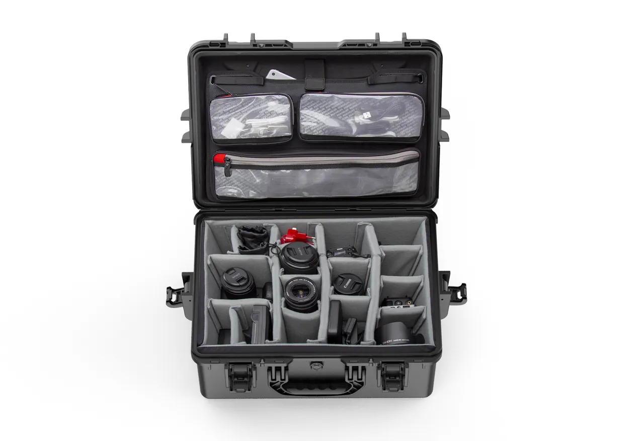
7. Sample Interfaces, Slits, Gas and Liquid Lines
Sample system interfaces and slits are small, precise and consequential, and are easily overlooked.
Entrance and exit slits. Slit width is typically between micrometres and tens of micrometres, and edge quality determines stray light level and line shape. Any impact or compression that deforms the edge changes the effective bandwidth. Protection points: a dedicated cavity for the slit assembly, a rigid guard, absolutely no clamping or compression over the slit region, and no shared cavity with tools or heavy items. Some spectrometer slits are replaceable modules, and before shipping it is worth confirming with the manufacturer whether they are installed or packaged separately.
Argon purge and gas fittings. OES type spectrometers usually need argon purging to avoid ultraviolet absorption. Risks to gas fittings are deformation or thread damage from impact, internal deformation from tubing compression, and loosening from repeated load between tubing and fitting under vibration. Protection points: protective caps on fittings, controlled and fixed tubing coil radius, never letting tubing become a load path, and confirming the gas circuit is in a safe state before shipping as the manufacturer instructs.
Liquid and cooling water circuits. The sample pump, peristaltic tubing and spray chamber of ICP type instruments mix consumables with precision parts. Protection points: remove peristaltic tubing and pack it separately so it does not take a compression set, dedicated cushioned cavities for the spray chamber and torch, protective caps on fittings, and never using the drain line as a load-bearing structure.
Vacuum and gas-filled optical chambers. Some spectrometers have optical chambers under vacuum or filled with inert gas, sealed by flanges and gaskets. Vibration changes flange bolt preload, and shock can damage sealing faces. Protection points: fix the overall attitude to limit load on the optical chamber, avoid pressure differentials acting on the case which at high sealing classes means fitting a pressure equalisation valve, and checking on arrival that vacuum or gas pressure is within the range the manufacturer allows.
Fibre probes and delivery fibres, for example in Raman systems. Fibre has a minimum bend radius, and an undersized radius raises macrobend loss or even breaks the core, while end face contamination reduces signal and raises background. Protection points: a dedicated cavity, a bend radius no smaller than the manufacturer value with allowance, end caps with clean packaging, and no shared cavity with heavy components.
8. Cleanliness and Particle Control
Cleanliness control is the capability that sets a spectrometer case apart from an ordinary instrument case.
Sources of contamination and their consequences. The contaminants that reach optical surfaces in transport and storage are mainly particles such as metal dust, abrasives, paper debris and fibre; oil mist and organic vapour from lubricants and packaging outgassing; water vapour and condensate; fingerprints and skin oils; and micro-organisms. In a spectrometer they appear as increased stray light, false peaks, baseline drift and reduced sensitivity. The hardest to handle is the haze formed by deposited organic vapour, since it produces no obvious particulate signature yet steadily reduces transmission.
Three levels of cleanliness control. Level one is packaging of the optical components themselves: gratings, lenses, optical windows and slits should be in a sealed clean state during transport, with optical faces never contacting packaging material directly. Level two is cavity isolation: optical, detector, gas and liquid, and tool cavities must be physically separated so dust cannot migrate in transit. Level three is case sealing and internal cleanliness: the sealing class determines the rate at which external dust enters, and the better the seal, the longer internal cleanliness is maintained.
Hard constraints on insert materials. Insert materials that contact optical components or share a sealed volume with them must deliver low outgassing, releasing no siloxanes, plasticisers or condensable volatiles; low particle shedding; no hard fillers, to avoid scratching; and chemical inertness. This must be established by material evaluation rather than appearance, because materials that look alike can differ greatly in outgassing. A comparison method is given in the Case foam material comparison.
Unpacking and installation cleanliness. Delivery documentation should state: open in a clean area, clean the bench and tools beforehand, wear clean gloves, install optical components immediately after removal or transfer them to a clean container, and avoid dust-generating work while the case is open. No packaging can compensate for contamination caused by leaving equipment open in a dusty area for a long time.
9. Humidity, Condensation and Purge Gas
Humidity control matters to a spectrometer twice over: it protects optical components and it protects hygroscopic materials.
Special requirements for hygroscopic materials. The potassium bromide (KBr) and sodium chloride (NaCl) windows common in infrared spectroscopy deliquesce very easily, fogging and losing transmission once they absorb surface moisture, and the damage is usually irreversible. Calcium fluoride (CaF2), magnesium fluoride (MgF2) and zinc selenide (ZnSe) are more moisture-tolerant but still require protection, and some infrared crystals degrade at the surface under humidity. Storage and transport humidity limits for infrared instruments are therefore notably stricter than for visible-range instruments, and the specific value must come from the instrument manufacturer rather than general experience.
How condensation forms and how to prevent it. Condensation occurs when a surface temperature drops below the dew point of the surrounding air. Two situations are typical: container rain in a sea freight container crossing climate zones, and moving directly from cold storage into hot humid air. Prevention means reducing the absolute water content inside the case through sealing, desiccant and packing in a low-humidity environment; slowing the rate of temperature change using the thermal inertia of the case; and avoiding abrupt transfers by equalising temperature before opening.
Desiccant selection and quantity. Selection points: capacity matched to the target humidity, rate matched to the transport duration with fast-acting types for short journeys and high-capacity long-lasting types for sea freight, no dust or corrosive by-products, and an indicating type for visual checking. Quantity should be calculated from free internal volume, packaging material moisture vapour transmission rate, transport duration and target humidity, with an allowance, never estimated roughly.
Purge and inert gas protection. Some spectrometers require the optical chamber to be filled with inert gas or kept under purge during transport, which suppresses water vapour adsorption and oxidation on optical surfaces. Points: use the gas type and pressure the manufacturer specifies; confirm the fittings do not leak, otherwise the gas escapes in transit and protection is lost; record fill pressure and time on the packing list; and verify pressure state on arrival. Where useful, a monitoring interface position can be provided in the case.
Combining sealing with pressure equalisation. A high sealing class brings a pressure problem: sealed at low altitude and shipped at high altitude or by air, the differential loads the case structurally and makes it hard to open. Cases at IP67 and above used for spectrometers should therefore be fitted with a pressure equalisation valve, which breathes slowly at a threshold differential while a hydrophobic and oleophobic membrane blocks liquid water and particles. Related structure and selection points are in Case pressure equalisation valve and IP67 protective case structure.
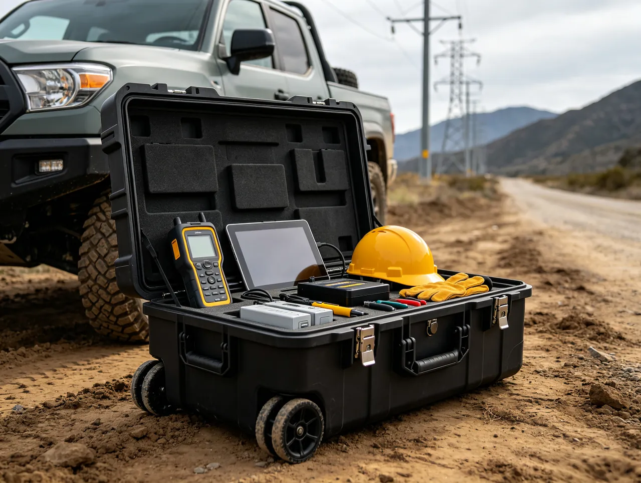
10. Vibration Isolation and Cushioning: Graded Design
Isolation must be graded by component sensitivity rather than applied uniformly to the whole case.
Distinguish shock from vibration. Shock is a short, high-amplitude event such as a drop, impact or emergency stop, needing sufficient cushion stroke and a suitable energy-absorbing material. Vibration is sustained, low-amplitude oscillation from road excitation and engine running, needing an appropriate natural frequency and damping to avoid resonance. The two require different countermeasures and must be designed separately.
Grading by sensitivity. Level one: interferometer mirror groups, grating and turret, optical bench, the most sensitive, needing the highest grade of isolation and attitude fixation. Level two: detectors, preamplifier circuits, gas and liquid fittings, moderately sensitive, needing cushioned fixation and ESD protection. Level three: housings, guards, tools and cables, relatively insensitive, needing impact and abrasion protection. Different levels must not share a cavity or cushion layer.
Avoid the padding-more-is-better trap. Cushion material must be matched to component weight: a material that is too soft compresses fully under a heavy load and loses its stroke, while too hard a material cannot absorb energy and transmits shock unchanged. Correct practice is to select material hardness and bearing area from cushion curves using component weight, the allowable acceleration limit given by the manufacturer and the expected drop height, then verify by test.
Low-frequency vibration and resonance. Road transport energy concentrates at low frequency, and if the system natural frequency falls inside the excitation band, resonance amplifies. This needs a combination of a lower natural frequency, added damping and multi-axis constraint. For heavier bench-type components a common approach is elastic support underneath, lateral stops and adjustable top clamping. Related structural design is in Cushion liner case design and Shock-sealed case design.
Attitude and transport locking. A spectrometer should retain its design attitude in transit. Where the manufacturer provides transport locking devices, such as interferometer locks, turret lock pins or beam path shutters, they must be applied as instructed and the state recorded on the packing list; and they must be released as instructed on arrival, otherwise the instrument will not work properly and may be damaged.
| Component level | Representative parts | Allowable condition (typical practice) | Insert scheme | Verification |
|---|---|---|---|---|
| --- | --- | --- | --- | --- |
| Level one | Interferometer mirror group, grating turret, optical bench | Per manufacturer acceleration limit | High-grade isolation, multi-point surface support, multi-axis location, attitude locking | Vibration test plus recalibration data comparison |
| Level two | Detectors, preamplifier circuits, gas and liquid fittings | Conventional precision instrument level | Cushioned fixation, ESD-safe cavity, fitting protection | Vibration and drop test plus function check |
| Level three | Housings, guards, tools, cables | Impact and abrasion protection | Separated fixation, surface protection, controlled radius | Visual and appearance inspection |
11. Sealing Class, Pressure Equalisation and Cable Penetrations
Sealing class is a basic specification, but its scope must be understood precisely.
Definition and recommendation. The dust and water ingress rating follows IEC 60529 internationally and GB/T 4208 in China, expressed as IP plus two digits. For spectrometer cases:
- IP54: only for short transfers in a controlled environment, not recommended for long-distance transport or storage.
- IP65: suitable for domestic transport and normal storage, dust-tight and protected against water jets.
- IP66: for transfer and site environments where hosing or heavy spray may occur.
- IP67: for sea freight export, long-term storage and the bench and detector cavities, and the recommended class for spectrometers.
- IP68: only where there is a genuine immersion risk.
Three boundaries that must be stated. First, the IP class does not indicate the humidity level inside the case, which persists if the case is sealed with humid internal air, so reducing it requires desiccant and low-humidity packing. Second, the IP class says nothing about vibration isolation; the two are independent and must be designed and verified separately. Third, the IP class is not radiation protection; for instruments containing a radiation source such as XRF, transport and storage must comply with applicable radiation protection management requirements, and a sealed case is not a radiation protection measure.
Key structures for achieving the seal. Common practice for IP67 includes a continuous closed-loop perimeter gasket with no joint in a critical position; controlled sealing face rigidity and flatness with groove tolerances matched to the gasket cross-section; multi-point latch preload design; a pressure equalisation valve; and sealed cable and interface penetrations. Related structural points are in Toolbox hinge, latch and seal structure and Case seal material selection.
Handling cable penetrations. Where power must be maintained in transit, for example for heating, dehumidification or data logging, cable has to pass through the case wall. The penetration is the weak point of the seal. Approaches include using a sealed bulkhead connector rather than crushing cable across the gasket, providing cable slack with strain relief, and fitting a quick-disconnect outside the case so opening does not pull on the instrument. Where power is not needed, avoid drilling the case at all to reduce sealing risk.
Gasket replaceability and service life. The gasket is a wear part and loses sealing performance through compression set, ageing and contamination. The structure should allow replacement without special tools, no re-adjustment of the overall structure afterwards, and standardised specifications for customer sourcing. Where material flammability matters, selection and verification can follow UL94 classification with testing of the actual part. Related life evaluation is in Protective case service life evaluation.
12. Custom Inserts and Cavity Schemes
The insert is the executing layer of protection and its design quality determines the outcome.
Bench and main unit cavity design points: multi-point surface support avoiding the spanning gap created by long rail supports; support points close to heavy component areas; avoiding bench openings and thin-wall regions; lateral stops limiting horizontal movement; adjustable top clamping limiting vertical bounce with no force on fragile areas; and operating space and a sight window for the transport locking device so its state can be confirmed.
Grating and turret area design points: local reinforcement by increasing support density under the turret region; no storage cavity or load-bearing structure in that region; and a separate cushion layer for the region rather than sharing with the rest of the main unit.
Detector cavity design points: ESD-safe material such as antistatic foam or static-dissipative insert; a dedicated cavity physically separated from the tool cavity; cushioning selected specifically for the detector weight rather than sharing the main unit cushion; thermal buffering for infrared detector cavities, which may use a low-conductivity material layer; and controlled cable coil radius with protected connectors.
Sample and accessory cavity design points: dedicated cushioned cavities for quartz and glass parts such as torches, spray chambers and optical windows; protective caps on gas and liquid fittings; peristaltic tubing packed separately; a dedicated fibre probe cavity with controlled radius and end face protection; and a separate dry document cavity. Custom machining processes are described in EVA foam insert custom process and Custom foam inserts guide; for flexible zoning see Case removable divider system.
| Cavity type | Contents | Key design parameters | Prohibitions |
|---|---|---|---|
| --- | --- | --- | --- |
| Main unit and bench cavity | Spectrometer main unit, optical bench | Multi-point surface support, lateral stops, adjustable top clamp, locking access | No long spanning rail support, no clamping on fragile areas |
| Turret and grating area | Grating turret, dispersion elements | Local reinforcement, separate cushion layer | No storage cavity above |
| Detector cavity | CCD/CMOS, PMT, infrared detectors | ESD-safe material, separate cushion, thermal buffer | No sharing with tools or consumables, no clamping |
| Quartz parts cavity | Torch, spray chamber, optical windows | Cushioned fixation, isolating soft pads, desiccant | No contact with metal parts |
| Gas and liquid cavity | Fittings, tubing, peristaltic tubing | Protective caps, controlled coil radius, independent fixation | Tubing must not be a load path |
| Fibre probe cavity | Raman probe, delivery fibre | Radius no smaller than specified, end caps, clean packaging | No small-radius bends, no compression |
| Document cavity | Manuals, calibration and test documents | Independently sealed, moisture protected, fixed position | No mixing with consumables |
13. Transport Testing: ISTA, GB/T 4857, ASTM D4169 and the MIL-STD-810H Note
Packaging effectiveness must be verified by citable standard testing.
The ISTA series is graded by transport form and weight: Series 1 non-simulation performance tests, Series 2 partial simulation, Series 3 general simulation including temperature and humidity conditioning, and Series 6 carrier-specific and e-commerce programmes. For a single spectrometer case, ISTA 2A suits partial simulation; for palletised case sets, ISTA 3E is closer to reality; and for export cargo with humidity requirements the conditioning of ISTA Series 3 is more complete. The process is described in ISTA transport testing procedure.
The GB/T 4857 series is the Chinese family of basic test methods for transport packages, covering vibration, shock, stacking and drop. For spectrometer cases the most important are vibration testing, after which the beam path state and fasteners must be checked and recalibration data compared to detect misalignment; stacking testing, which evaluates structural stability under warehouse and container stacking; and drop testing, which evaluates the integrity of case and contents in an accidental drop. The method is analysed in GB/T 4857 transport packaging testing.
ASTM D4169 combines distribution cycles with assurance levels and suits sea freight and intermodal transport. It is described in ASTM D4169 distribution cycle testing.
| System | Emphasis | Typical spectrometer scenario | Common procedures |
|---|---|---|---|
| --- | --- | --- | --- |
| ISTA | General simulation and carrier specific | Export case sets, palletised dispatch | 3E, 3A, 2A |
| GB/T 4857 | Domestic road and rail | Domestic distributor and laboratory delivery | Vibration, stacking, drop series |
| ASTM D4169 | Intermodal distribution cycle | Overseas projects, sea and land combined | DC12, DC13 and similar |
Additional verification items:
- Recalibration comparison after vibration. This is the most direct and effective verification for a spectrometer. Measure wavelength accuracy, repeatability and baseline noise before and after the vibration test and use the difference to judge the effectiveness of the isolation scheme.
- Shock recording. Place impact indicator labels and a transport data logger inside the case and collect data on real shipments to iterate the insert design.
- Cleanliness verification. Place cleanliness witness plates in the optical cavity and count settled particles after shipping under real conditions.
- Humidity verification. Place a temperature and humidity logger inside the cavity, record the humidity profile of the journey, and for infrared instruments check specifically that the manufacturer limit was not exceeded.
- ESD verification. Measure the surface resistance of insert materials to confirm it falls in a sensible range, and carry out a practical opening test in a dry season to observe any discharge.
- Reassembly and unlock verification. Simulate the on-site workflow to confirm the unlock steps for transport locking devices are clear and need no special tool, or that the special tool ships with the case.
Where a customer asks to reference MIL-STD-810H, it may be used as an environmental test method basis for designing test conditions such as high-temperature storage, low-temperature storage, damp heat cycling, vibration endurance and transport drop. It must be made clear that the standard is a test method standard and not equivalent to military certification, and no military certification claim may be made. Related notes are in MIL-STD-810H as an environmental test basis.
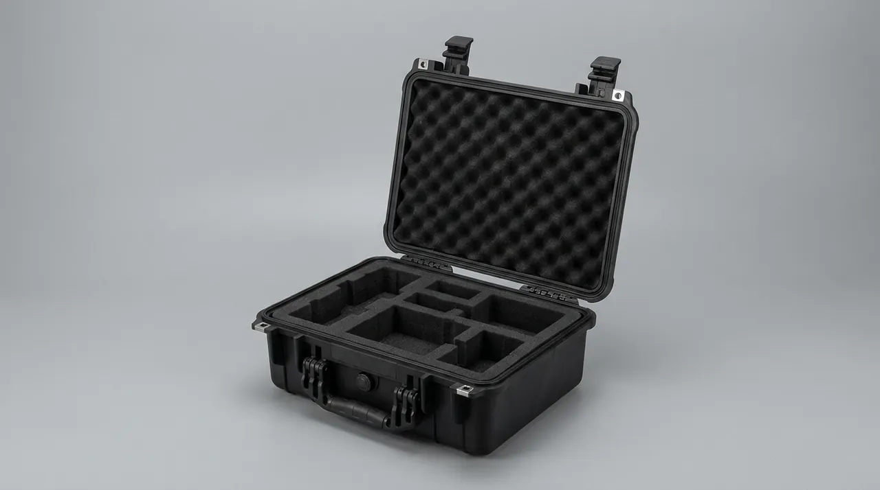
14. Procurement Acceptance, AQL, Selection Table and Export Recalibration
When buying spectrometer cases in volume, acceptance criteria must be written into the contract.
Recommended incoming inspection items:
- Appearance and dimensions: external and cavity dimensions match the drawing; no cracks, sink marks or flash; sealing face flat.
- Sealing performance: sample check to the agreed class, continuous perimeter seal fit check, gasket replaceability confirmed.
- Structural strength: sample static load test at the rated multiple held for the specified time, confirming no permanent deformation or cracking; sample corner drop or simulated drop.
- Insert fit: trial assembly with the actual item or a gauge confirming no interference, no point contact and smooth removal; confirm there is no hard contact point anywhere in the optical and turret regions.
- ESD check: surface resistance measurement for the detector cavity insert, plus documented ESD properties.
- Cleanliness check: visual inspection of the optical cavity for particles, fibre and odour; obtain outgassing or cleanliness documentation for the insert material.
- Humidity control measures: desiccant type, quantity and placement; humidity indicator card; pressure equalisation valve function.
- Marking and documentation: content, position and durability of markings; completeness of documents; document cavity sealing effective.
AQL sampling method. Sample size and acceptance criteria follow batch size, inspection level and AQL value. For spectrometer cases the recommendation is a tighter AQL for critical defects such as seal failure, an insert that puts optical components in contact with hard material, structural cracking, failure to meet ESD requirements, or a cavity dimension error preventing assembly, and a looser AQL for minor defects such as colour variation, light flow marks or font differences. The method and tables are in Custom case acceptance and AQL.
Specification selection table:
| Cargo category | Recommended case type | Insert and protection scheme | Sealing class recommendation | Suggested transport testing |
|---|---|---|---|---|
| --- | --- | --- | --- | --- |
| Spark OES complete unit | Heavy-duty isolating case | Multi-point surface support, integral isolation, gas fitting protection | IP65 | ISTA 3E plus vibration plus recalibration comparison |
| ICP series main unit | Heavy-duty isolating case | Main unit isolation, dedicated quartz cavity, tubing limits | IP65/IP67 | ISTA 3E plus vibration plus drop |
| FTIR main unit | High-rigidity isolating case | Highest-grade isolation, attitude locking, mirror group limits | IP67 | ISTA 3E plus vibration plus recalibration comparison |
| Raman main unit and probe | Zoned isolating case | Laser isolation, dedicated fibre cavity, end face protection | IP67 | ISTA 2A plus vibration plus cleanliness verification |
| XRF main unit | Heavy-duty protective case | Dedicated cushioning for the tube, attitude fixation, compliance marking | IP65 | ISTA 2A plus vibration plus compliance review |
| Handheld and portable | Portable protective case | Profile-matched cavity, window protection, dedicated battery cavity | IP67 | ISTA 2A plus drop |
| Spare optical components | Clean box plus dedicated cavity | Clean packaging, low-outgassing material, desiccant | IP67 | ISTA 2A plus cleanliness witness plates |
Export and storage points:
- Moisture and condensation are the primary risk. Sea freight containers crossing climate zones condense; a sealing class of IP67 or above is recommended with a pressure equalisation valve and calculated desiccant, and infrared instruments need particular attention to humidity limits. Where required, the test plan can follow an ASTM D4169 distribution cycle.
- Structural strength for repeated handling. Export cargo passes through factory loading, port storage, vessel loading, discharge and inland transport, so case corners, lifting points and the base need reinforcement.
- Regulations and documentation. Instruments containing a radiation source may attract additional compliance requirements in cross-border transport, so country requirements should be checked at quotation stage, and radiation protection markings must not be obscured.
- Storage. Store in a temperature-stable, humidity-controlled area away from heat sources and external walls and not directly on the floor; replace desiccant and check the humidity indicator card after every opening; inspect gasket and insert condition periodically. Methods and care are covered in How to clean a protective case and Protective case service life evaluation.
- Recalibration on arrival. Fixing wavelength and intensity verification against factory data into the delivery process gives both a quality record and the most valuable evidence for judging packaging effectiveness.
JUNZHJIA provides complete custom delivery capability in analytical instruments: developing high-rigidity cases and inserts around spectrometer main unit and optical bench structures, grading isolation and location by component sensitivity, fitting ESD-safe dedicated cavities for detectors, matching desiccant and pressure equalisation valves to humidity requirements, reserving marking and document positions for export, and supplying OEM/ODM manufacturing with stable volume delivery. Kexin New Materials (Guangdong) Co., Ltd. operates a complete chain from structural design, tooling development and rotomoulding or injection moulding through insert machining and case assembly, serving instrument manufacturers, distributors, third-party testing laboratories and instrument rental services. For a first engagement we recommend a small trial batch and physical trial assembly including isolation and ESD verification, moving to volume supply once verified. Partner evaluation points are in How to choose a case OEM factory.
Frequently Asked Questions
Q: What is the biggest difference between a spectrometer case and an ordinary instrument case? A: The biggest difference is that spectrometer protection is system level rather than component level. Inside a spectrometer one rigid beam path links the optical bench, grating and detector, and the three tolerate a given stress completely differently. The bench demands structural rigidity and dimensional stability, since any bending changes the beam path geometry. The grating turret demands angular accuracy, since a tiny rotation shifts wavelength calibration. The detector demands fixed position, freedom from ESD damage and reliable thermal management. Protecting only one link achieves nothing, because even with an excellent detector cavity a bent bench shifts the spot and the detector no longer receives light in the right place. Spectrometer failures are also hidden: micron-scale bench deformation and tiny grating angle shifts are invisible in an arrival inspection and show up only when recalibration data for wavelength accuracy, repeatability and baseline noise are compared. A spectrometer case must therefore deliver high-rigidity integral support, beam path isolation, detector protection by type, and humidity and cleanliness control throughout. Q: How do you tell whether a spectrometer has suffered optical misalignment in transit? A: Appearance inspection is essentially useless and data is essential. Judge at three levels on arrival. First, wavelength verification: check wavelength accuracy and repeatability with a standard source or reference material and compare against factory data; a systematic shift or degraded repeatability usually points to the grating turret mechanism or a change in bench geometry. Second, resolution and line shape verification: observe whether lines have broadened or become asymmetric, which usually points to bench bending or slit edge deformation. Third, baseline noise and stray light verification: rising baseline noise or abnormal false peaks usually points to optical surface contamination or loosened internal baffles. Transport records matter too: impact indicator labels and a transport data logger inside the case reveal whether a shock event exceeded the set threshold. The most effective practice is to fix arrival recalibration against factory data into the delivery process, which both detects problems promptly and accumulates the data needed to evaluate and improve the packaging scheme. Q: Why can a grating not be cleaned by wiping? A: Because the ruling surface of a grating is an extremely fine periodic microstructure and any wiping causes irreversible damage. The surface usually carries a reflective coating, and ruling density can reach several hundred to several thousand lines per millimetre, meaning the feature scale is at or below the surface roughness of common wiping materials. Cleaning with ordinary wipes or cloth, however gently, leaves scratches, compression marks or embedded fibre in the ruling surface, increasing scattering and producing false peaks; wiping also tends to push particles into the grooves and worsen contamination. Given that, the design principle for grating protection is do not touch, do not disturb, do not contaminate: optical faces never contact packaging material directly in transport or storage; insert materials must be low-shedding, low-outgassing and free of hard fillers; the grating cavity must be physically separated from tool and consumable cavities so metal dust and fibre cannot migrate; and where the manufacturer provides a transport locking device it must be applied as instructed to restrict turret rotation. Once a grating is contaminated in service, the correct action is to contact the manufacturer for professional handling or return it to the factory, not to clean it on site. Q: What matters particularly when shipping an FTIR spectrometer? A: Two things matter most: transport locking of the interferometer and moisture protection for infrared optical materials. The position accuracy of the moving or corner-cube mirror inside the interferometer directly determines spectral quality and it is the most vibration- and tilt-sensitive part of the instrument, which is why most FTIR instruments have a dedicated mechanical locking device such as a locking screw or pin. The lock must be applied strictly as the manufacturer instructs and its state recorded on the packing list; on arrival it must equally be released as instructed, otherwise the instrument will not work properly and may be damaged. On moisture, infrared optical materials differ greatly: KBr and NaCl windows deliquesce very easily, fogging and losing transmission once they absorb surface moisture with usually irreversible damage, while CaF2, MgF2 and ZnSe are more tolerant but still need protection. Storage and transport humidity limits for infrared instruments are therefore noticeably stricter than for visible-range types, and the specific figure must come from the manufacturer rather than general experience. Sea freight condensation risk needs IP67 sealing, a calculated desiccant quantity and a pressure equalisation valve working together. Q: Why are detectors sensitive to static, and how should they be protected? A: Because electrostatic discharge is extremely fast, on the nanosecond scale, but its energy is enough to punch through the gate oxide of a silicon detector or permanently kill pixels. In most cases this damage does not immediately stop the instrument working; it shows up as localised pixel failure, rising dark current or increased noise, which makes it a hidden failure whose cause is very hard to trace after arrival. Static sources are everywhere in transport and unpacking: friction and separation between plastic packaging materials, friction between insert material and instrument housing, walking and contact by personnel in air below about 30 percent RH, and temporarily wrapping equipment in ordinary plastic film. Protection works at three levels. At the material level, use antistatic bags, conductive foam or static-dissipative inserts and measure surface resistance to confirm a sensible range. At the structural level, provide a sensible grounding path in the case or insert so grounding can be applied when needed. At the procedure level, require operators to wear antistatic wrist straps, avoid repeated opening and friction in low humidity, and never wrap a detector temporarily in plain plastic film. The design thinking behind ESD shielded cases is relevant here. Q: What sealing class does a spectrometer case need? A: IP67 is recommended, under IEC 60529 and its Chinese counterpart GB/T 4208. The reason is that spectrometers need moisture protection twice over: optical coatings hydrolyse and grow mould under prolonged high humidity, and the KBr and NaCl windows used in infrared instruments deliquesce very easily with usually irreversible damage, while condensation in a sea freight container crossing climate zones is worse still. IP67 is dust-tight and protects against harmful water ingress under temporary immersion, which suits long-distance transport and storage. Three boundaries must be stated clearly. First, the IP class describes the case resistance to water and particles and does not indicate internal humidity, so lowering humidity requires desiccant and low-humidity packing. Second, the IP class says nothing about vibration isolation; the two are independent parameters. Third, the IP class is not radiation protection; for instruments containing a radiation source such as XRF, transport and storage must comply with applicable radiation protection management requirements and a sealed case is not a radiation protection measure. For short domestic transfers in a controlled environment IP65 is usually sufficient. Q: How should custom insert material be selected? A: There are three hard constraints. The first is low outgassing: insert materials that touch optics or share a sealed volume must not release siloxanes, plasticisers or condensable volatiles, because these accumulate inside a sealed case and deposit on optical surfaces as a haze that reduces transmission and is difficult to remove; this must be established by material evaluation, not appearance, since materials that look alike can differ greatly. The second is low shedding and no hard fillers: the material must not generate fibre or particles through friction, and its surface must be free of hard fillers that could scratch an optical surface. The third is material selection by functional zone: the optical cavity and turret area take low-outgassing, low-shedding types; the detector cavity needs ESD performance, so antistatic foam or static-dissipative material; the quartz parts cavity needs compliant cushioning to avoid impacts; and the infrared detector cavity may add a low-conductivity layer to improve thermal buffering. In addition, cushion hardness must be selected separately for the weight and allowable acceleration limit of the part carried, and components at different levels must not share one cushion layer, because a cushion layer is designed around a specific weight and sensitivity. Q: What checks and recalibration should be done after a spectrometer arrives? A: Six steps are recommended. Step one, review transport records: check impact indicator labels and data logger output to see whether a threshold event occurred. Step two, prepare the unpacking environment: open in a clean, dust-free area, wear clean gloves, and avoid grinding or other dust-generating work while the case is open. Step three, release the transport locks: release interferometer locking screws, turret lock pins and similar devices as the manufacturer instructs; this step is mandatory and omitting it will stop the instrument working properly and may damage it. Step four, inspect appearance and mechanisms: check the housing, interfaces, quartz parts, gas and liquid fittings and cabling for impact deformation. Step five, equalise the environment before power-up: if the instrument has been in a cold environment, let it stand in the new environment for a period before opening and energising to avoid condensation. Step six, recalibrate and compare data: verify wavelength accuracy, repeatability, resolution, baseline noise and sensitivity against factory data; fixing this comparison into the delivery process gives both a quality record and the most valuable evidence for judging packaging effectiveness. Q: What should be considered when shipping an instrument containing a radiation source, such as XRF? A: Four things. First, the compliance precondition. Instruments containing an X-ray tube may attract applicable radiation protection management requirements and transport regulations, so work must follow applicable regulations and manufacturer instructions and country and mode requirements should be checked at quotation stage, rather than discovering at dispatch that they are unmet. Second, the integrity of radiation protection markings. Warning labels must be clearly visible and not obscured by case structure, and accompanying radiation protection documents must be complete and stored where they are protected from moisture. Third, the instrument structure itself. The X-ray tube is a high-voltage vacuum device vulnerable to mechanical shock, and relative movement of internal electrodes affects output stability, so it needs a dedicated cushioned cavity and integral attitude fixation, while the detector window needs clean protection against contamination. Fourth, the boundary must be stated clearly: the case is a transport and storage protection structure, not a radiation protection measure, and cannot replace any radiation protection management requirement; protection during power-up, commissioning and use must be carried out by qualified personnel in accordance with applicable regulations and standards.
Conclusion & Related Reading
The design core of a spectrometer case is treating one rigid beam path as a single unit while applying graded protection by component sensitivity. For the optical bench, what must be protected is the geometric datum: multi-point surface support avoids local bending, lateral stops and adjustable top clamping constrain all degrees of freedom, thermal buffering slows dimensional change, and transport locking is applied as instructed to fix key mechanisms. For the grating and dispersion elements, what must be protected is angular accuracy and ruling surface cleanliness: do not touch, do not disturb, do not contaminate, and judge the outcome after transport from wavelength data rather than appearance. For detectors, protect by type: silicon devices are mainly an ESD problem, photomultiplier tubes mainly a cushioning and magnetic-distance problem, and infrared detectors mainly a thermal buffering and strict humidity problem. The thread connecting all three is cleanliness and humidity control: low-outgassing, low-shedding insert materials, physically isolated cavities, a calculated desiccant quantity, and a pressure equalisation valve that is essential at high sealing classes.
For spectrometer manufacturers, distributors, third-party testing laboratories and instrument rental services, the sensible sequence is: first grade by instrument type and component sensitivity, with the interferometer and grating most sensitive, the bench next and detectors differentiated by type; then determine the isolation scheme, location method, ESD measures and humidity requirements for each level; then develop inserts for the main models and carry out physical trial assembly confirming there is no hard contact point in the optical and turret regions; then verify vibration, stacking and drop to ISTA, GB/T 4857 or ASTM D4169, using the difference in recalibration data before and after vibration as the core evidence of effectiveness; and finally write acceptance criteria, marking systems, document lists and locking and unlocking procedures into the delivery documentation. JUNZHJIA supports the whole path from structural design, isolation and clean insert development and ESD cavity configuration through trial samples to volume supply, with Kexin New Materials (Guangdong) Co., Ltd. manufacturing and delivering to customer instrument specifications and analytical requirements, so that a spectrometer retains usable optical performance and data reliability from factory dispatch, storage and transport through to laboratory recalibration.
Related Reading