

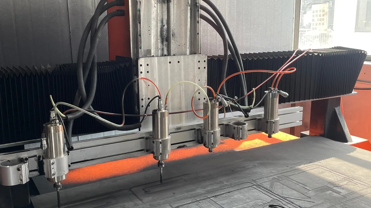
A float glass line is a long chain of equipment: the melting furnace, the tin bath, the annealing lehr, and the cold-end cutting and stacking stations. The equipment that actually governs downtime is rarely the furnace or the bath itself. It is the parts that come off the line for periodic repair and are swapped inside a tight maintenance window: furnace gates and gate frames, cooling water jackets, doghouse lip plates, transition rolls and dams in the tin bath, edge rollers and top rollers, linear motor stators, lehr rollers, and cold-end conveyor rollers. These parts span an enormous range of shapes. Some are heat-resistant castings weighing several hundred kilograms; others are hollow rolls eight to nine metres long with a length-to-diameter ratio above fifty. Their surfaces are equally sensitive, often carrying a ground mirror finish, a chrome layer, a ceramic coating, or a castable refractory lining.
JUNZHIJIA's position: protecting float glass line components requires cleanliness, geometric accuracy and structural strength to be engineered at the same time. A case is not a container; it is a mobile operating environment that carries a part through the shutdown window. The sections below break down the two hardest categories, furnace gates and tin bath rolls, and give parameters, tables and acceptance criteria that can be written directly into a purchase specification.
Table of Contents
- Float Glass Lines: The Transport Challenge from Furnace to Tin Bath to Lehr
- Furnace Gates: Damage Modes and Protection for Heat-Resistant Castings
- Tin Bath Rolls and Transition Rolls: Fighting Bending and Surface Scoring
- Case Materials and Structure: Copolymer PP, Glass-Filled PP and PC/ABS
- Compartments and Cushion Liners: How EPE, EVA, IXPE and PU Work Together
- Sealing Systems: Seven Details That Turn a Rating into Reality
- Latches, Hinges and Stacking Load: Structural Checks for Heavy Cases
- Temperature, Humidity, Salt Fog and Condensation: Corrosion Control
- Transport Test Validation: ISTA, GB/T 4857 and ASTM D4169 Combined
- Acceptance Criteria and Unpacking Inspection Checklist
- Customization, Tooling and OEM/ODM: Six Milestones from Drawing to Mass Production
- Selection Checklist: Matching Case Configuration to Part Type
- Frequently Asked Questions FAQ
- Conclusion and Related Reading
Float Glass Lines: The Transport Challenge from Furnace to Tin Bath to Lehr
In the float process, batch is charged into the furnace, melted, refined and homogenised at 1550 to 1600 degrees Celsius, then flows through a canal controlled by a gate into the tin bath. There it spreads, polishes and is drawn thin or thick on molten tin. It then passes over transition rolls into the annealing lehr and finally reaches the cold end for cutting, snapping and stacking. Spare parts along this line divide into two families: those that touch molten glass or the glass ribbon, and those that do not. A contaminated or scratched contact part leaves a permanent defect on the ribbon. A structural part that loses its geometry cannot be aligned on installation and has to come off the line again.
The table below is a protection profile of common float line parts and the starting point for case selection. For large flat panel transport, see Building Glass Transport Cases. For the packaging logic of high-temperature furnace equipment, see Industrial Furnace Component Cases.
| Part | Typical size and weight | Sensitive area | Main transport failure mode |
|---|---|---|---|
| --- | --- | --- | --- |
| Canal gate / waist gate | 800x600x180 mm, 120-400 kg | Gate lip, sealing face, lifting lugs | Lip chipping, sealing face impact, lug deformation |
| Gate frame and water jacket | 1000x700x300 mm, 150-500 kg | Weld bevel, water nozzle thread | Broken nozzle, damaged bevel, internal rust |
| Tin bath roll / transition roll | 150-300 mm dia x 3500-9000 mm, 300-1500 kg | Mirror roll face, journals, bearing seats | Bending beyond tolerance, surface scoring, journal impact |
| Edge roller, top roller head | 400x400x300 mm, 60-200 kg | Tooth flank, guide face, air ports | Rust seizure, tooth damage |
| Lehr roller | 120-200 mm dia x 4000 mm, 200-600 kg | Roll face, shaft end | Bending, scoring |
| Linear motor stator, sensor | 1200x300x200 mm, 80-250 kg | Magnet face, junction box | Magnetic contamination, box impact |
A float line shutdown window is typically only 24 to 72 hours, while spares are often dispatched weeks in advance, travelling by interprovincial road, coastal feeder and sometimes ocean container. Every knock, every condensation cycle and every improper lift during transit surfaces at once when the line stops. The question the case must answer is therefore not whether the part fits, but whether it can be installed the moment it arrives.
Furnace Gates: Damage Modes and Protection for Heat-Resistant Castings
The furnace gate controls glass flow and temperature zoning. By position it is a canal gate, a waist gate or a doghouse gate; by construction it is either a monolithic casting or a steel shell with a castable refractory lining. Monolithic gates are commonly made of Cr26 high-chrome cast iron or a heat-resistant cast steel of the ZG35Cr24Ni7SiN family, while composite gates carry a low-cement refractory poured inside a steel shell. The two constructions fail differently in transit: the casting is vulnerable at the lip and sealing face, the composite at the lining and shell.
The gate lip is a machined wedge or arc that meets the canal brick and the water jacket to form the throttling passage. A chip of one or two millimetres shifts flow control and changes the temperature distribution of the molten glass. The sealing face is usually planed or ground to a roughness of Ra 1.6 to 3.2; a single dent leaks glass. The lifting lugs carry the whole gate and cannot be deformed if it is to hang correctly.
| Failure mode | Main cause | Recommended protection |
|---|---|---|
| --- | --- | --- |
| Lip chipping | Point impact, lip bearing load in the case | EVA locating blocks 15-25 mm each side, lip face covered by 5 mm IXPE only, never load-bearing |
| Sealing face impact | Collision with case wall or adjacent part | Separate compartment, hard dividers at least 40 mm apart, 10 mm EPE on the mating face |
| Lug deformation | Sling crushing, stacking load landing on lugs | Lug relief pocket in the case, stacking force carried by case posts |
| Refractory lining cracks | Vibration fatigue, thermal shock during handling | Wooden pallet plus EPDM rubber isolation, side stops to prevent secondary movement |
| Nozzle or thread damage | Exposed thread, rubbing against the case | Thread protector plus dedicated compartment, never shared with metal parts |
| Surface rust | Humid sea freight without vapour protection | VCI film wrap, desiccant, humidity indicator card |
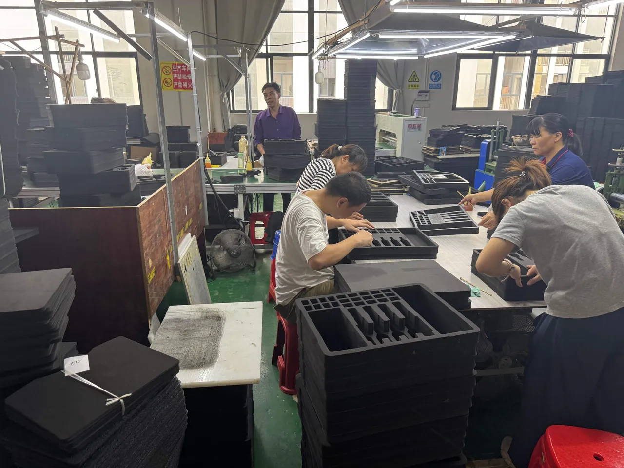
For composite gates, the moisture content of the castable matters. The lining is normally dried before dispatch, but if it reabsorbs moisture in a humid store, a fast heat-up in the furnace can cause explosive spalling. Relative humidity inside the case should be held below 50 percent and a humidity indicator card placed inside, so that the site team reads the card before deciding whether the gate can go straight into the furnace. For comparable heat-resistant castings, see Foundry Ladle Transport Cases.
Tin Bath Rolls and Transition Rolls: Fighting Bending and Surface Scoring
Tin bath rolls, transition rolls and lehr rollers are the classic long, slender, precise parts of a float line. A 200 mm diameter, 8000 mm long roll has a length-to-diameter ratio of 40, while a ground roll is often specified to a straightness of 0.05 mm per metre or better and a surface roughness of Ra 0.2 to 0.4. Two consequences follow: if the support points are wrong, the roll sags under its own weight in transit; if the roll face touches any hard material, it takes a scratch that cannot be repaired.
Bending is a ratio of moment to stiffness. For a simply supported beam under a uniform load, the maximum deflection is five times the load per unit length times the length to the fourth power, divided by 384 times the modulus and the moment of inertia. The fourth-power term means that halving the support span cuts deflection to one sixteenth. The first measure for a long roll is therefore not a thicker case wall but more support points and a shorter span. The rule of thumb is three points up to six metres, four points from six to eight metres, and five points or a dedicated saddle trailer beyond eight metres.
| Parameter | Recommended value | Purpose |
|---|---|---|
| --- | --- | --- |
| Number of supports | Up to 6 m: 3 points; 6-8 m: 4 points | Lower the peak bending moment |
| Support span | No more than one third of the roll length, and no more than 2500 mm per span | Limit mid-span sag |
| Transport deflection limit | No more than 0.3 mm/m and no more than length divided by 5000 | Preserve ground straightness |
| Gap between saddle and roll face | 8-15 mm per side | Clearance against rubbing |
| Journal wrapping | 3 mm EVA plus 0.2 mm anti-rust paper | Protect against both impact and rust |
| Roll face to case wall | At least 50 mm | Resist side impact |
| Saddle material | Polyurethane or EVA at Shore A 50-60 | No scoring, no imprint |
Roll face protection uses three layers. The innermost is PE stretch film to keep out oil and dust, the middle is 5 to 8 mm IXPE for a fine, imprint-free cushion, and the outer is a fleece or needle-punched nonwoven wrap before the roll rests on the EVA saddle. Journals and bearing seats must never touch metal, and slings must not be wrapped directly around the roll face; lift with soft belts placed on the non-working surfaces either side of the journal.
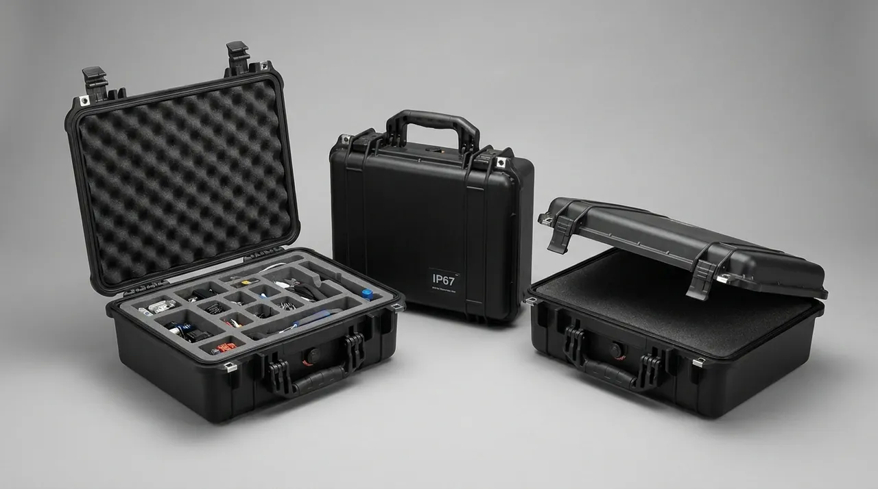
A transition roll assembly often arrives with bearing housings, cylinders and cooling water fittings attached. It should not be treated as a plain roll. The accessories go into their own compartment so that vibration cannot swing them into the roll face. For related roller and drive components, see Conveyor Roller Cases.
Case Materials and Structure: Copolymer PP, Glass-Filled PP and PC/ABS
The case material sets low-temperature toughness, impact resistance, chemical resistance and weight. Float line spares are often stored outdoors or in semi-open areas, where winter temperatures outside a workshop can reach minus 25 degrees Celsius and coastal sites stay humid and salty all year. Material selection cannot rest on room-temperature strength alone.
| Material | Density, g/cm3 | Tensile strength | Low temperature | Best fit |
|---|---|---|---|---|
| --- | --- | --- | --- | --- |
| Copolymer PP | 0.90-0.91 | 25-30 MPa | Usable to -20 C | Ambient transfer, light loads |
| PP with EPDM modification | 0.91 | 22-28 MPa | No brittle fracture to -30 C | Northern winters, cold chain |
| PP-GF20 / GF30 | 1.04-1.12 | 55-80 MPa | Reasonable toughness to -30 C | Heavy load-bearing cases, long roll cases |
| PC/ABS blend | 1.15 | 50-60 MPa | Impact resistant to -40 C | Precision heads, instrument bays |
| Rotomoulded HDPE | 0.94 | 20-28 MPa | Tough below -40 C | Very large or irregular parts, one-off tooling |
| Aluminium frame with PC panels | - | - | - | Precision parts, frequent opening |
Wall design follows a simple rule: thin skins, thick ribs, generous corners. A 4 to 6 mm skin keeps the large surface area stiff and thermally sensible, while rib roots thicken to 6 to 8 mm to avoid sink marks and stress concentration. The load-bearing base runs 6 to 8 mm with a grid of ribs, and all outside corners radius at 8 mm or more, with inside corners at 6 mm or more, spreading impact and easing ejection. Glass-filled PP demands attention to weld line strength, so gate positions must avoid latch and hinge bosses.
For very long roll cases, an injection-moulded shell alone rarely delivers both stiffness and length. A hybrid structure is common: aluminium profiles or steel tubes run as longitudinal keels, clad in PP or PC panels. The case stays reasonably light while its stacking capacity exceeds that of a pure plastic box by a multiple.
Compartments and Cushion Liners: How EPE, EVA, IXPE and PU Work Together
A cushion liner does two separate jobs. Location keeps the part from moving under vibration; energy absorption cuts the shock acceleration down to what the part can survive. Foams differ widely in density, compressive strength and rebound, and the value comes from combining them.
| Material | Density, kg/m3 | 25 percent compression | Rebound behaviour | Role in the case |
|---|---|---|---|---|
| --- | --- | --- | --- | --- |
| EPE pearl foam | 25-35 | 60-120 kPa | High, repeated compression | Bulk void filling, layer separation |
| EVA | 60-120 | 150-400 kPa | Strong energy absorption, tear resistant | Lip clamps, journal locating blocks |
| IXPE | 33-100 | 100-250 kPa | Fine, imprint-free | Contact layer on ground or coated faces |
| PU foam | 30-60 | Formulation dependent | Good rebound, mouldable | Moulded cavities for irregular parts |
| PP honeycomb or plywood | - | Rigid | Non-deforming | Hard dividers, load-bearing base |
The recommended stack is: contact layer of 3 to 5 mm IXPE against the part, locating layer of 10 to 20 mm EVA carved or die-cut to the outline, cradle layer of 30 to 50 mm EPE or a moulded PU cradle, then a hard divider of PP honeycomb or plywood above the case base. The hard divider cuts the movement path between compartments so that two parts cannot chase and strike each other under vibration.
Mixed loads need attention to galvanic compatibility. Stainless and carbon steel must not touch directly, and aluminium and galvanised parts need an insulating divider between them. A linear motor stator containing magnets goes into its own shielded bay, away from ferrous tools. Compartments should allow 3 to 5 mm of assembly clearance, enough to hold the part firmly without forcing it in so hard that removal becomes difficult. For a systematic comparison of liner materials, see Internal Foam Types for Cases.
Sealing Systems: Seven Details That Turn a Rating into Reality
IEC 60529 and GB/T 4208 describe enclosure protection against solids and liquids with two digits. The first digit 6 means dust-tight; the second digit 5 means protection against water jets, 7 means temporary immersion, typically one metre for thirty minutes, and 9K addresses high-pressure hot water jets. Float line spare part cases usually settle at IP65, covering rain and washdown, or IP67, covering short immersion at a dock, water ingress in a hold, or full immersion cleaning. A rating is not a number printed on a plate; it is the sum of seven details.
- Seal groove profile. A dovetail or trapezoidal groove with a gasket compression of 25 to 35 percent is preferred. Too little compression leaks; too much takes a permanent set and shortens service life.
- Gasket material. Silicone handles minus 60 to 200 degrees Celsius for storage near hot workshops; EPDM resists weathering and water vapour for coastal outdoor use; a sponge silicone gasket keeps closing force low on large lids.
- Corners and joints. Corners must be moulded and vulcanised as one piece, never mitred from strip. Where a joint is unavoidable, use a 45-degree scarf with a dedicated adhesive and add fixings within 30 mm either side.
- Mating face flatness. Flatness of the lid-to-body face should be 0.3 mm per 300 mm or better. Beyond that, local gaps leave the gasket uncompressed.
- Latch spacing. Latch spacing along the long side should not exceed 120 mm, and 60 mm at the corners, so the gasket is loaded evenly around the rim.
- Pressure equalisation valve. When the pressure difference reaches 3 to 5 kPa, the gasket is pushed open or sucked in. A valve with a hydrophobic membrane lets air through while blocking water droplets; mount it on the upper side wall, away from standing water and direct spray.
- Accessory penetrations. Cable glands, nameplate rivets and drain holes each need their own washer or sealant. Any untreated hole defeats the first six items.
For a first screening, a pressure decay test at 20 kPa held for 60 seconds works well, followed by spray or immersion confirmation at the rated level.
Latches, Hinges and Stacking Load: Structural Checks for Heavy Cases
Float line spare part cases are heavy. A gate case can exceed 500 kg and a long roll case is longer still. If latches and hinges are not checked against load, they open in transit. Use 304 stainless steel over-centre latches fixed with moulded-in nuts rather than self-tapping screws, and hinges with a metal pin and a PA bushing rated for at least 10,000 cycles without loosening.
| Check item | Recommended target | Note |
|---|---|---|
| --- | --- | --- |
| Static stacking | At least 5 high, at least 1200 kg per case | 24 hours at 25 C, deformation no more than 2 mm |
| Dynamic stacking in transit | 3 high | Load spectrum per ISTA 3E or GB/T 4857.3 |
| Latch count | At least 3 per long side, 2 per short side | Even gasket compression |
| Hinge cycle life | At least 10,000 cycles | No fracture, no axial play |
| Lifting points | Four lugs, safety factor at least 4 | Lift force bypasses the gate lugs |
| Forklift pockets | Clear height 90-120 mm | Forks must not hit the base or the contents |
| Side impact | No fracture in a 30 cm edge drop | Per GB/T 4857.5 |
Stacking load is fundamentally the axial stability of the case posts. Closed-section posts or steel tube inserts raise the buckling capacity sharply, while the lid interlocks with the body through ribs so that stacking force does not press on the centre of the lid. Very long roll cases are not normally stacked; where stacking is unavoidable, use locating pads at both ends so that the upper case bears on the end supports rather than the mid-span.
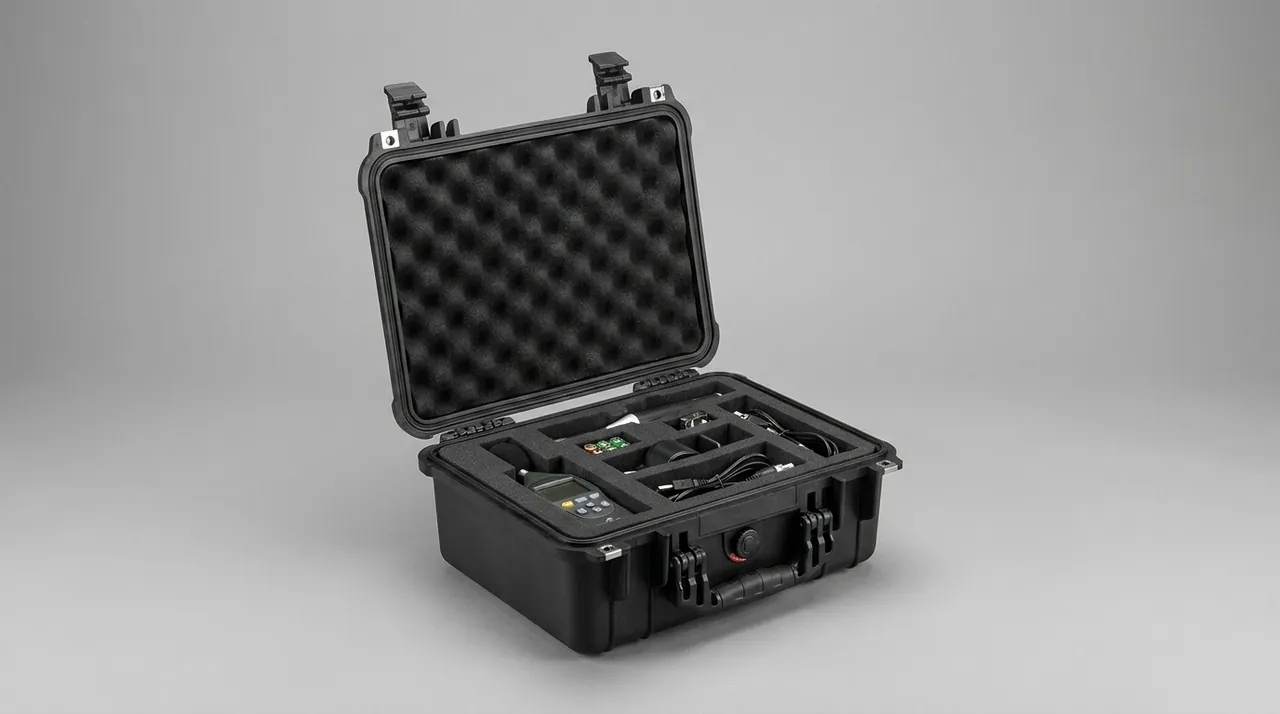
Pallet planning and stacking height are limited by container internal height and terminal limits; for arranging them, see Stackability and Pallet Planning.
Temperature, Humidity, Salt Fog and Condensation: Corrosion Control
Corrosion kills float line spares quietly. A thin film of rust can mean a seized linkage or a failed thermocouple after installation. Risk varies with the scenario, so the response should be graded.
| Scenario | Main risk | Protection |
|---|---|---|
| --- | --- | --- |
| Climate-controlled store, 15-30 C, RH 60 percent or less | Low | Standard dust and moisture control |
| Coastal plant, RH 75 percent or more, salt aerosol | Medium to high | EPDM gaskets, 316 fasteners, exposed metal parts to 480 h salt fog |
| Ocean container, daily swing over 20 C, hold RH up to 95 percent | High | VCI film, desiccant, pressure equalisation valve |
| Cold region, minus 30 C | Low temperature embrittlement | Case material modified to -30 C, silicone gaskets |
| Near a hot workshop, up to 60 C | Softening and ageing | Avoid PVC liners, choose silicone or EPDM |
The most dangerous factor in ocean freight is not steady humidity but the breathing cycle driven by day-night temperature swing. Air expands and escapes by day; as it cools at night, damp air is drawn back in, and after repeated cycles the interior condenses. The fix has two parts: VCI film forms a molecular protective layer on metal surfaces while desiccant absorbs residual moisture, and a pressure equalisation valve provides a controlled breathing path so incoming damp air meets the desiccant first.
As a rough guide, allow 30 to 50 g of montmorillonite desiccant per 0.1 cubic metre of internal net volume, taking the upper figure for hot and humid routes, and include a humidity indicator card. If the card has changed colour on arrival, the case experienced condensation and the metal parts need re-inspection. Salt fog testing follows the neutral salt spray method of GB/T 10125; carbon steel fasteners usually call for 240 hours, and parts stored long term on the coast call for 480 hours or more.
Transport Test Validation: ISTA, GB/T 4857 and ASTM D4169 Combined
However good a case design looks on paper, it is unproven until it survives simulated transport. For float line spare part cases, validate with four combined elements: vibration, shock, stacking and temperature-humidity preconditioning. Test the case loaded with the actual part, not empty.
| Test | Reference method | Criterion |
|---|---|---|
| --- | --- | --- |
| Random vibration | ASTM D4169 / ISTA 3E | No part movement, no mutual impact, no case cracking |
| Sine sweep | GB/T 4857.10 | Resonance amplification no more than 2 |
| Drop, corner, edge and face | GB/T 4857.5 | Case intact, latches stay closed |
| Stacking | GB/T 4857.3 | Deformation no more than 2 mm after 24 hours |
| Temperature and humidity preconditioning | GB/T 4857.2 | No condensation inside, indicator card unchanged |
| Neutral salt spray | GB/T 10125 | No red rust on metal parts after 480 hours |
Sequence matters: precondition with temperature and humidity first, then vibrate, then drop. This exposes the worst combination, in which strength falls after moisture uptake and the part is then shock loaded. For long roll cases, mount an accelerometer at mid-span on the vibration table and confirm the response does not sit in a resonant amplification band. For method and programme selection, see ISTA Transport Testing Procedures.
Acceptance Criteria and Unpacking Inspection Checklist
For volume deliveries, inspecting every case is neither economic nor necessary. Use GB/T 2828.1 counting sampling at general inspection level II, with an AQL of 2.5 for appearance defects and 1.5 for functional defects. Inspection items fall into appearance, dimensions, function and documentation.
| Category | Item | Criterion |
|---|---|---|
| --- | --- | --- |
| Appearance | No sink marks, flash or cracks | No obvious defect at 300 mm viewing distance |
| Dimensions | External length, width, height; internal compartment sizes | Plus or minus 2 mm or 0.3 percent, whichever is greater |
| Function | Gasket compression, latch pull, valve breathing | Compression 25 to 35 percent; latch holds at 800 N |
| Structure | Stacking and drop sampling | Per the criteria in sections 7 and 9 |
| Documentation | Packing list, material certificate, test report, drawing | Complete and matching the goods |
| Marking | Part name, number, this-way-up and no-tilt marks | Matching the packing list, not peeling |
Unpacking should follow a fixed checklist: inspect the outer case for damage and moisture traces, read the humidity indicator card, verify numbers against the packing list, and finally check surfaces and critical dimensions on the part. Sampling ratios and criteria are covered in Custom Case Acceptance AQL. Any failed functional item should pause acceptance of the whole batch and trigger traceability, never a simple swap of the bad unit.
Customization, Tooling and OEM/ODM: Six Milestones from Drawing to Mass Production
Custom parts have no off-the-shelf case, so the customisation process has to be disciplined to avoid discovering, after tooling, that nothing can change. JUNZHIJIA breaks the process into six milestones, each with a defined deliverable.
- Requirement review and part survey. Take a STEP model or scan the part in 3D, confirming outline, centre of gravity, fragile faces and lifting points.
- Protection concept. Fix the cushion stack, compartment count, sealing level, stacking height and lifting method.
- Structure design and DFM review. Check draft angles of 1 to 2 degrees, even wall thickness, rib layout, and the strength of latch and hinge bosses.
- Sample case validation. Build a 3D printed or aluminium-tool prototype and run drop, vibration and spray screening before freezing dimensions.
- Tooling and trial. Cut the steel or aluminium mould, run the T1 trial to confirm dimensions, appearance and assembly, and rework the tool if needed.
- Mass production and first article. First article report, in-process patrol inspection, pre-shipment sampling and shipping documentation.
MOQ and lead time depend on structural complexity. A variant that reuses an existing mould and only changes the liner can go to volume at a few hundred units, while a new heavy long roll case needs time reserved for mould design and trial. In ODM projects the customer may supply only the part and the use scenario, leaving case design to the manufacturer; in OEM projects the case is built and branded to the customer drawing and standard. Drawing ownership, tool ownership and patent clauses should be settled in the contract for both models.
Selection Checklist: Matching Case Configuration to Part Type
Condensing the guidance into a single tick-box table shortens specification writing considerably.
| Part type | Case material | Liner solution | Sealing | Stacking | Special requirement |
|---|---|---|---|---|---|
| --- | --- | --- | --- | --- | --- |
| Furnace gate up to 400 kg | PP-GF20 | EVA locating plus IXPE contact | IP65 | 5 high static | Lip not load-bearing, lug relief |
| Gate frame or water jacket | Copolymer PP | EPE plus wooden pallet | IP54 | 4 high | Nozzle thread protectors |
| Tin bath roll, 3.5-6 m | PP-GF30 long case | Moulded PU cradle plus V blocks | IP65 | Single layer preferred | 3 supports, deflection no more than length over 5000 |
| Transition roll assembly | PP-GF20 | EVA plus hard dividers | IP67 | 3 high | Independent journal location, separate accessory bay |
| Edge roller head | PC/ABS | Moulded PU cavity | IP67 | 4 high | Tooth flank rust protection, port plugs |
| Cold-end conveyor roller | Copolymer PP | EPE separation | IP54 | 5 high | Anti-scoring, end caps |
One general rule applies throughout selection: define what must not be touched before choosing cushioning, define what must not bend before choosing supports, and only then consider appearance and cost. Reversing that order usually surfaces structural problems at the acceptance stage.
Frequently Asked Questions FAQ
Q: Why is a wooden crate packed with straw unsuitable for a furnace gate?
A: Straw compresses to almost zero thickness, so there is effectively no cushion and no location. The gate moves freely inside the crate and its lip and sealing face strike the walls or timber bearers on every bump. Worse, straw absorbs moisture and becomes a continuous wet source, so a composite gate lining reabsorbs water and metal parts rust. The correct approach is a rigid case with EVA blocks clamping both sides of the lip, a 5 mm IXPE contact layer, the lip itself never load-bearing, and VCI film plus desiccant controlling internal humidity. A wooden crate also lacks the stiffness for multi-layer stacking, so the stacking load transfers straight into the gate. Above 200 kg, use a glass-filled PP or steel-framed case with a lug relief pocket inside. Timber also has no defined compression set, so the same crate behaves differently every time it is packed, which makes the protection impossible to validate against a transport test standard.
Q: Tin bath rolls are extremely long. How do you keep the case from letting them bend?
A: Bending resistance depends on support layout, not case wall thickness. Under a uniform load, deflection scales with the fourth power of the support span, so halving the span cuts deflection to one sixteenth. In practice, use three support points up to six metres, four between six and eight metres, and keep each span under 2500 mm. Saddles in polyurethane or EVA at Shore A 50-60 with 8 to 15 mm clearance per side hold the roll without scoring it. The case itself gains global stiffness from aluminium keels clad in PP panels, which also stop the case twisting during lifting. Set the transport deflection limit at 0.3 mm per metre and no more than length divided by 5000, and confirm with an accelerometer at mid-span on the shaker that the response is not resonantly amplified. Where a roll must travel by road across provinces, consider a dedicated steel cradle bolted to the trailer bed, which takes the case out of the load path altogether.
Q: How do you choose between IP65 and IP67 for glass line parts?
A: Choose by the actual exposure, not by wanting the highest number. IP65 keeps dust out and resists water jets from any direction, covering plant rain, washdown and short storms, which is the right landing point for most gate cases and short-haul transfer boxes. IP67 allows temporary immersion and suits cases crossing flooded dock areas, exposed to water ingress in a hold, or needing full immersion cleaning, such as a transition roll assembly case. Higher ratings mean higher gasket closing force, more latches and harder opening, so cost and maintenance effort rise with them. The test is simple: will the part possibly sit under water for thirty minutes during transport or storage? If not, IP65 is enough; if yes, choose IP67. Note too that a rating covers the enclosure only and never solves condensation, which needs VCI and desiccant. Where mixed loads share one container, place IP67 cases nearest the floor and the door, since that is where standing water is most likely.
Q: For sea freight to Southeast Asia, how should salt fog and humidity be handled to avoid rework?
A: Handle external salt and internal condensation as two separate problems. For external salt, switch exposed metal parts and fasteners to 316 stainless, use EPDM gaskets, and require 480 hours with no red rust under the neutral salt spray method of GB/T 10125. For internal condensation, wrap metal working faces in VCI film, add montmorillonite desiccant at 30 to 50 g per 0.1 cubic metre of net internal volume with the upper figure for hot humid routes, and fit a pressure equalisation valve so the case breathes in a controlled way. Place a humidity indicator card inside, and read it first on arrival: a colour change means condensation occurred and the metal parts need re-inspection. In the container, keep cases away from the door and from overhead drips, and leave a ventilation gap to the container wall. Record the exposure assumption in the purchase specification, because a case ordered as IP65 and then left on an open quay will not behave like an IP67 unit.
Q: How should EPE, EVA and IXPE foams be combined?
A: Divide the work into contact, location and cradle layers. The contact layer touching the part is 3 to 5 mm IXPE, which is fine and imprint-free, suited to ground roll faces and coated surfaces. The locating layer is 10 to 20 mm EVA, carved or die-cut to the outline; it has high compressive strength and tear resistance and locks the part in position. The cradle layer is 30 to 50 mm EPE or a moulded PU cradle that absorbs high-energy shock. Add PP honeycomb or plywood dividers between compartments to cut the movement path. Never fill a whole case with one material: pure EPE is too soft to locate, pure EVA is too stiff to compress under small shocks, and IXPE alone is too thin. Where mixed metals share a load, add insulating dividers to prevent galvanic corrosion. Cut the locating layer slightly proud of its pocket so the part is held in light compression rather than floating loose.
Q: Our part is non-standard and we have no drawing. Can you still customise, and how long does tooling take?
A: Yes. Without a drawing we normally scan the part in 3D, convert the point cloud into a STEP model, and measure the centre of gravity, lifting points and fragile faces. For hot parts we also confirm the thermal history so the liner material is not chosen below its service temperature. The process then runs through a protection concept and structural design, a prototype or sample case for validation, and tooling once dimensions are frozen. Timing depends mainly on structural complexity and tool type: reusing an existing mould and changing only the liner is fastest, while a new heavy long roll case needs time reserved for mould design, machining and trial. As an interim step before steel tooling, an aluminium frame with PP panels is a low-cost way to validate the structure. Ask for the scan report and the frozen STEP model as project deliverables, so a repeat order can be produced without scanning the part again.
Q: Will a pressure equalisation valve let water in, and which side should it be on?
A: A properly specified valve uses a hydrophobic membrane or a labyrinth path so that air passes while water droplets do not, and it will not admit water in normal service. That comes with conditions: the valve body must not sit under standing water for long periods, and must not face high-pressure spray directly. Mount it on the upper part of a side wall, clear of the base where water collects, of the lid where rain lands, and of the forklift contact area. Seal the thread with a washer and sealant. The valve keeps the pressure difference from exceeding 3 to 5 kPa and pushing the gasket open or sucking it inwards, and it suppresses the breathing that drives damp air back inside. A case with no vent at all will distort its lid and pop its latches as temperature swings. Match membrane airflow to the net internal volume; too little airflow defeats the purpose.
Q: How should a batch of protective cases be accepted, and how many should be sampled?
A: Use GB/T 2828.1 counting sampling at general inspection level II, with an AQL of 2.5 for appearance defects and 1.5 for functional defects, reading the sample size from the tables by lot size. Inspection covers four categories. Appearance checks sink marks, flash and cracks. Dimensions cover the external envelope and internal compartments, with a tolerance of plus or minus 2 mm or 0.3 percent, whichever is greater. Function covers gasket compression at 25 to 35 percent, latch pull holding 800 N, and valve breathing. Documentation covers the packing list, material certificate, test report and shipping drawing. Structural items such as stacking and drop belong to type validation on a sampled basis, not every case. Any failed functional item should hold the whole lot and trigger traceability rather than releasing only the good units.
Conclusion and Related Reading
One avoided site rework outweighs the cost of the case that prevented it. JUNZHIJIA builds protection programmes for furnace gates, tin bath rolls and transition roll assemblies, with custom liners and OEM/ODM. Manufactured by Kexin New Materials (Guangdong) Co., Ltd.
Related Reading