

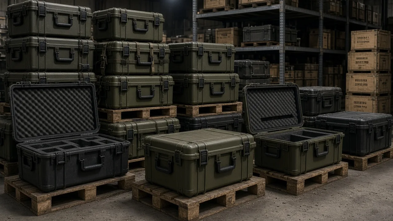
A Hand Tools Case is the most common personal container on maintenance, assembly, overhaul and inspection sites. Buyers tend to look first at shell thickness, latch count and handle styling, and only after delivery discover that the layer inside the lid governs the daily experience. The liner decides whether a wrench, a screwdriver and a caliper each sit in the right slot, and it decides how many extra movements a technician needs when one hand steadies the case in a confined space and the other reaches for a tool.
This article stays strictly on the container side of the subject: shell, lid, liner, compartments, hinges, latches, gaskets, reinforcement ribs, handle, coating and marking. Where MIL-STD-810H is mentioned, it is cited as an environmental test methodology that may inform test design; it does not represent any military certification outcome. The applicability of any standard or compliance requirement is ultimately governed by the purchase contract and local regulations.
The Role of a Hand Tools Case: Why the Liner Decides Usability
The difference between a hand tools case and a socket set case or an electronics case is the payload. Hand tools are irregular in shape, wildly unequal in length, and they must be taken out and put back many times during a working day. A 250 mm adjustable wrench and a 60 mm precision driver share one box, yet they demand completely different treatment in terms of space, cushioning and restraint. The shell answers only whether the case survives being carried and stacked. The liner answers whether the tools stay put, are found quickly, and are returned safely.
Field failure statistics for this product family are revealing. Complaints are rarely about a cracked shell. They cluster around three issues: tools shifting inside the case and chipping each other's cutting edges; missing slots that force the user to rummage every time; and liner material absorbing moisture or shedding dust onto precision surfaces. All three point at liner design, not shell strength. Conversely, a case with a modest shell but an excellent liner usually earns a higher field satisfaction score than a heavily thickened shell fitted with a single flat foam pad.
There is one more piece of logic that is easy to miss: the liner is the human machine interface. Once the lid opens, the position of every tool, the effort to extract it, and the uniqueness of the return position are all communicated by the geometry of the foam. The liner works as an instruction sheet that needs no text. The closer it follows the sequence of use, the less hesitation and misplacement occurs on site.
Four Basic Liner Formats and Where Each One Fits
Engineering practice recognises roughly four liner formats. The first is the routed cavity, machined into a solid block of foam to match tool outlines. It offers the highest positional accuracy and suits fixed tool sets, but it becomes scrap the moment the tool list changes. The second is pick-and-pluck foam, built from a pre-cut grid that the user tears to create openings. It is flexible and fast to deploy, at the cost of ragged walls and positional accuracy that degrades with every tear. The third is the divider system, using rigid or semi-rigid panels to partition space. It resists shifting better than foam and cleans easily, but its energy absorption is limited. The fourth is the hybrid: foam for cushioning, dividers for zoning, elastic webbing or clips for restraint, mixed according to tool family.
Which format to choose depends on three variables: how scattered the tool shapes are, whether tools leave the case for remote use, and whether the liner must evolve as the tool list changes. Fixed lists with irregular shapes and off-site use favour the routed cavity. Frequently changing lists, small batches and short delivery cycles favour pick-and-pluck combined with dividers. When a project sits between the two, a structured comparison across positional accuracy, modifiability, cushioning, cleanability and unit cost is more useful than intuition; see dividers versus foam liner for one such framework.
Foam Selection: EVA, PU, XPE and EPE Compared
Liner foam is not a case of softer being better. It participates in the design through three parameters: compression load capacity, resilience and weathering stability. EVA is the most common engineering choice for hand tool liners. Density is adjustable, resilience is high, cut edges are clean, and it suits slots that are opened and closed all day. Its drawbacks are cost and the fact that low-density grades still take a permanent set under prolonged compression. PU foam feels soft and absorbs energy well, which makes it a good interface layer at slot bottoms or under the lid, but it is moisture sensitive and powders as it ages, so it should not live permanently inside a damp case. XPE and EPE are polyolefin foams: waterproof, low density and cost effective, which makes them economical choices for filling and partitioning, though their higher compression set rules them out of high-precision routed cavities.
One step that is often skipped but matters a great deal is asking the foam supplier for density, compressive strength at 25 percent deflection, and compression set data, rather than accepting a sample on feel alone. When a case mixes edged metal tools with measuring instruments, a thin high-density sheet under the slot floor prevents a cutting edge from pressing a permanent channel through low-density foam. For more on matching foam to case geometry, see toolbox internal foam selection.
Compartments, Restraint and Anti-Shift Geometry
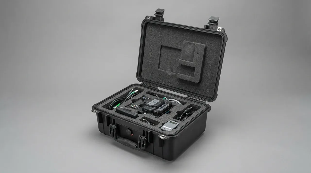
Shifting is simply the existence of free travel inside the case. Removing that travel can be done three ways: geometric restraint, friction restraint and elastic restraint. Geometric restraint is the most reliable. The slot profile hugs the load-bearing faces of the tool, and where necessary a step, boss or local narrowing forms a detent so that extraction can only follow one direction. Friction restraint relies on interference, meaning the slot is slightly smaller than the tool and the foam grips it. Interference is usually measured in millimetres; too much makes extraction a fight, too little means nothing at all. Elastic restraint uses webbing, hook-and-loop tape, shock cord or an engineering-plastic clip to press the tool down, and it suits items that vary too much in shape to route a cavity.
The priority order should be: solve it geometrically before relying on friction, and use mechanical clamping before relying on interference. The reason is that foam slowly loses resilience under temperature cycling and repeated compression, so interference grip decays over time, whereas the authority of a moulded detent or a clip is largely insensitive to ageing. When a set contains several sizes of the same tool type, leave a marking position beside each slot, such as an embossed number, a colour block or a silk-screened size, so that returning a tool to its one correct place becomes a visual task instead of a memory task. For complex mixed lists, the layout methods in designing a removable divider system and pre-cut foam and removable divider techniques are worth reviewing.
Quantifying Access Efficiency: Cycles, Path Length and Gloved Handling
Access efficiency sounds subjective, but it decomposes into four measurable quantities: the number of discrete actions needed to extract one tool, the length of the hand travel path, the minimum visual resolution required, and the discrimination time on return. Action count runs from opening the lid to the tool leaving the case, and counts each grab, rotate and lift movement. Path length is the cumulative distance the wrist and forearm travel inside the case. Minimum visual resolution asks whether the user must see slot detail clearly in order to return a tool correctly. Discrimination time is the mental processing needed to confirm the right position.
The most effective way to improve all four is to place high-frequency tools in the first visual layer and on the shortest travel path once the lid is open, pushing low-frequency items and spares to lower layers or side pockets. In practice the interior can be zoned into three tiers by usage frequency: the first tier holds the three to five tools used on every task, either in the lid or on an upper tray; the second tier holds periodically used sizes; the third holds spares and consumables. One further condition is routinely overlooked: gloves. Field work usually requires them, and gloves substantially reduce tactile feedback and pinch precision. Slot openings must therefore be sized for a gloved finger, and every fine rotate-or-pinch motion must be simplified. A liner validated bare-handed will almost certainly generate feedback along the lines of "it goes in fine but you cannot get it out".
Tool Tracing and Cavity Machining Routes
With a routed cavity liner, roughly eighty percent of the quality is decided by tracing. Tracing is normally done on the physical tool, capturing three things: the maximum projected outline, the step changes through the thickness, and which face can serve as the locating datum. The choice of datum face decides whether the slot is easy to load. Setting the datum on the face where the tool naturally rests produces a stable attitude in the slot, reducing wobble and the need to re-align a tool before it drops in.
On the machining side, the common route is CNC milling of a solid foam block, which gives high profile accuracy and permits fillets and draft angles. The alternative is thermoforming, where a sheet of foam is heated and formed over a tool, offering high batch efficiency and excellent surface consistency but weaker fidelity on complex three-dimensional outlines than milling. A practical compromise is to cut the block into zones first and then mill only the complex profiles, balancing throughput against precision. After machining, deburring and dust extraction are mandatory; residual chips migrate into moving parts of tools and cause premature wear. The trade-offs of pre-formed inserts are covered in more detail in pre-cut foam insert process notes.
Lid, Hinges and Opening Angle
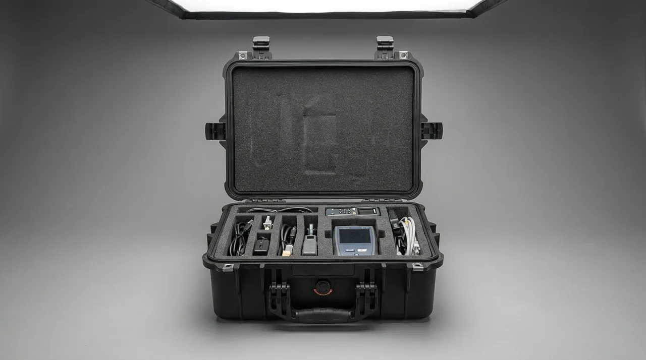
The lid of a hand tools case performs two jobs: compression and presentation. Compression means that, once closed, the liner or a pressure strip holds tools in their slots so they cannot escape during transport. Presentation means the inside of the lid can carry additional tool positions or a document pocket, extending usable area. The two jobs pull opening angle in different directions: a short hinge travel favours compression, while presentation benefits from a wide opening angle, occasionally to the point where the lid lies almost flat against the bench.
Hinge selection must answer both life and travel limitation. Life is expressed in open-close cycles, and a hand tools case sees far more cycles in daily use than a long-haul transit case, so pin wear resistance deserves close attention. Travel limitation means a built-in stop, or a linkage or tether that caps the opening angle, preventing the lid from folding back and crushing cables behind the case or tipping the whole box over. On latches, hand tools cases usually use single or double draw latches, and the compression travel must be matched to the liner's compression volume: the thicker and firmer the liner, the more latch take-up must be reserved. The division of labour between hinges, latches and gaskets is explored further in what the hinge, latch and gasket actually do.
Handle, Centre of Gravity and Loaded Carrying
Carrying a fully loaded hand tools case is where design weaknesses surface first. The handle must carry not just the static weight but the dynamic amplification that appears when walking, and that factor rises noticeably on stairs, kerbs and uneven ground. The design target is therefore not "it can be lifted" but "it does not deform, detach or cut into the hand under dynamic load".
The effect of centre of gravity on carrying comfort is badly underrated. The liner layout determines the mass distribution, and if heavy items sit on the far side from the handle, the case rotates as it is lifted and the user's wrist must fight the resulting moment. A better arrangement puts the heaviest tools in the bottom layer directly under the handle, and lays long tools parallel to the long axis of the case, so that the horizontal projection of the centre of gravity falls close to the handle. When total tool weight is high, the handle-to-shell connection also needs checking: the handle mounts should transfer load into the wall through a thickened zone or a metal insert rather than concentrating it on a thin panel. The difference between static and dynamic handle verification is set out in static and dynamic handle load testing.
Wall Thickness, Ribs and How the Liner Cooperates
Shell stiffness and liner compression are coupled parameters. A thin wall with dense ribs deflects elastically under load; if the liner is a solid block of foam, that deflection squeezes both foam and tools together and generates extra grip force. A thick, stiff wall keeps grip force comparatively stable. Conversely, an over-thick, over-stiff wall erodes the liner's cushioning benefit, because impact energy passes through the rigid panel straight into the foam.
The sensible approach is zoned design. Load-concentration areas such as corners, handle mounts, hinge bosses and latch anchors get extra thickness and ribs to guarantee stiffness. Non-critical panels can be reduced in thickness and even allowed limited elastic deflection so that the liner does the energy absorption. It is important to remember that the liner is itself part of the case cross-section. If its compression volume is set too large, the closing pressure may exceed what the latch can hold, and over time the latch loosens or the lid warps. Liner thickness, compression volume and latch take-up should be verified as one parameter set, never chosen independently.
Sealing and Moisture Control: The Liner as Part of the Envelope
Whether a hand tools case needs waterproofing depends on the environment. Indoor or workshop use is satisfied by dust and splash resistance. Outdoor, marine, wellsite and rainy-season work demands an explicit IP rating supported by a gasket, uniform peripheral compression and a pressure-equalisation element. The point worth stressing is that the liner is not a bystander in the sealing system. Foam absorbs moisture, and moisture held in foam is released into the case as temperature rises, creating a locally humid microclimate that accelerates rust on steel tools.
For damp environments, therefore, prefer closed-cell foam and fit a replaceable desiccant compartment. For precision items stored long term, leave a limited air path between liner and shell so that a fully enclosed moisture trap cannot form, and pair this with the case's gasket and pressure-equalisation design to limit ingress from outside. Third, remove heavy tools for long-term storage so the liner is not held under load, because a compacted zone loses both cushioning and moisture capacity. If storage is measured in months, schedule periodic airing and desiccant replacement.
Liner Maintenance, Replacement and Service Life
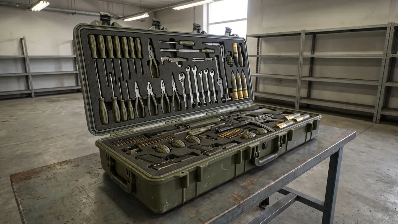
The liner is the component with the strongest consumable character. Its life is normally shorter than the case's for three reasons: resilience decay from repeated compression, embedding of oil and metal swarf, and crack propagation from cut edges. Three signals indicate it is time to replace: slot walls retain a visible set long after a tool is removed; a visible gap opens between slot profile and tool; or the foam surface shows cracks, shedding or widespread oil staining.
Maintenance follows three principles: dry, clean and light. Use a mild detergent and a soft cloth, and keep solvent-based cleaners away from EVA and PU foam, because solvents attack the closed-cell structure and accelerate ageing. Heavily oiled slots should be blotted first, then wiped. If a case is kept in standby storage, remove the heavy tools and store them separately so the liner is not permanently compressed. When replacing, prefer the original liner specification: the slot profile and case dimensions were designed as a set, and a substitute with the same material and similar outline can still lose its grip through a few millimetres of profile deviation. Buyers who want to extend liner life should contract for the liner as a separately supplied spare part with defined minimum order quantity and lead time.
Stacking, Transport and Static Creep
In warehouse and transit stages, hand tools cases are stacked. Stacking tests the shell with long-term static load, and it tests the liner with its ability to recover after compression. When a liner carries stacking load for a long period at elevated temperature, the foam creeps: after opening, slots appear shallower and grip is weaker. For spare-part cases kept in storage for extended periods, limit the number of stacked layers and the duration of static load, or relieve the liner by having packing elements route the load into the shell structure.
Dynamic transport adds vehicle vibration and road shock. The typical consequences are loosened fasteners and liner fatigue: hinge pins, latch rivets and handle bolts can all work loose under sustained micro-motion, so the acceptance criteria should include a fastener torque re-check after vibration testing. Stack stability verification can follow the workflow in stacking load test for cases.
Inspection, Acceptance and Common Failure Modes
Incoming acceptance should run in three layers. The first is appearance and dimensions: sinks, warpage, flash and impact marks on the shell; uniformity of the gap between lid and body; and liner-to-wall contact without bridging or voids. The second is function: hinge travel smooth and quiet, latch compression reaching the stop and releasable one-handed, handle not deforming under full load, and gasket continuous around the full perimeter. The third is fit: load the actual tool list, then check profile contact, absence of shifting, and whether tools can be extracted and returned while wearing gloves.
Common failure modes fall into five groups: slot relaxation that lets tools shift; foam that absorbs moisture or sheds particles onto precision parts; latch compression decay that lets the lid lift; hinge pin wear or rivet loosening that makes the lid sloppy; and local shell cracking at the handle mounts. The first two are liner design issues, the last three are structure and hardware issues, and acceptance sampling should be weighted towards the higher-risk groups. Where sampling inspection is used, agree the plan and the non-conformance rules in the contract, and list liner compression recovery and thickness dimensions as key characteristics.
A Procurement Checklist to Avoid Rework
First, be wary of equating a thicker shell with a better case. Shell thickness is only one stiffness parameter; rib layout, resin grade and thickness distribution together determine structural behaviour, and the liner is the component actually protecting the tools. Second, be wary of recycled-content liner foam. Recycled foam has inconsistent density and resilience; nothing looks wrong at first, but after two or three months slots relax across the board, so require resin grade and batch consistency evidence in the contract. Third, be wary of a liner that drifts out of step with the tool list. Tool lists change during project execution, and if the liner design freezes too early, delivery produces the familiar mismatch of a case that arrived with tools that changed, so lock a tool list revision before liner release and negotiate one small-change window.
Fourth, be wary of accepting on drawings alone. The critical liner properties are grip force and ease of extraction after assembly, neither of which a drawing can express, so physical build verification is mandatory. Fifth, be wary of ignoring spare parts. Liners, gaskets, handles and latches are all wear items, and the contract should define supply route, minimum order quantity and lead time so that one broken component does not take a whole case out of service. Sixth, be wary of forcing one liner design across different scenarios. An indoor overhaul case and a field inspection case have distinctly different protection needs, and sharing one liner usually leaves both applications poorly served.
Closing Perspective: Making Every Pick-and-Place Effortless
The competitiveness of a hand tools case is not measured by how thick the shell feels, but by the few seconds after the lid opens: whether the tools are visible at a glance, extracted on the first attempt, and located the moment they are returned. Treating the liner as a human machine interface, breaking access efficiency into measurable action counts and path lengths, and grounding compartment, restraint and material choices in the actual tool list and usage frequency is what turns a case into a working part of the job rather than an accessory to be tolerated. For buyers, putting the liner into the technical specification and build verification into acceptance are the two most direct steps towards a case that is genuinely usable rather than merely rugged.
Frequently Asked Questions
Q: Why does the liner of a hand tools case matter more than shell thickness? A: Shell thickness addresses overall stiffness and impact tolerance, which answers whether the case survives carrying and stacking. The liner addresses positioning, cushioning and access inside the case, which answers whether tools are protected and found quickly. Field feedback confirms the split: nearly all complaints concern shifting tools, chipped cutting edges, rummaging time and liner dust, and every one of those traces back to the liner. More importantly, a poor liner cannot be compensated for later by thickening the shell, because the liner defines the interior geometry and the tolerance chain around every tool. The right sequence at selection stage is to treat the liner as a design object of equal weight to the shell: define the tool list, usage frequency and access context first, then derive liner format, material and restraint method from those inputs.
A useful rule of thumb is to treat the liner budget as a first-class line item in the technical specification, with its own acceptance criteria, rather than as an accessory bought once the shell dimensions are already frozen.
Q: Which scenarios suit routed cavities, pick-and-pluck foam, dividers or hybrid liners? A: A routed cavity machined into solid foam delivers the highest positional accuracy and the smoothest extraction, and it suits fixed tool lists with irregular shapes, but it becomes scrap when the tools change. Pick-and-pluck foam is a pre-cut grid the user tears to size: flexible, quick to deploy and low on tooling cost, which suits frequently changing lists and small batches, at the cost of ragged walls and positional accuracy that degrades with every tear. Divider systems use rigid or semi-rigid panels and resist shifting better than foam while cleaning easily, which suits regular shapes and small parts, but they absorb little energy and are a poor choice for edged tools and instruments. Hybrid liners mix roles by tool family, for example foam for cushioning, dividers for zoning and webbing or clips for clamping, and they are the most common answer for complex lists. The deciding criterion is how scattered the tool shapes are and how stable the list is.
Q: How should EVA, PU, XPE and EPE foam be divided between roles in a liner? A: EVA has adjustable density, high resilience and clean cut edges, making it the natural body material for slots that open and close all day. PU feels soft and absorbs energy well, so it suits slot floors and lid padding, but it is moisture sensitive and powders as it ages and should not be used permanently in damp cases. XPE and EPE are polyolefin foams with good water resistance, low density and low cost, which suits filling, partitioning and broad cushioning panels, although their higher compression set rules them out of precision cavities. Real designs are usually laminated: a structural layer of EVA keeps slot shapes stable, a thin high-density sheet stops cutting edges from pressing through, and a filling layer of XPE or EPE controls volume and cost. When specifying, request density, compressive strength at 25 percent deflection and compression set data, and accept on those numbers rather than on how the sample feels in the hand.
Q: How can access efficiency be measured instead of judged by feel? A: Build four metrics. First, the action count to extract one tool, from opening the lid to the tool leaving the case, counting each grab, rotate and lift; three actions or fewer is a good result. Second, hand travel path length, which shortens markedly when high-frequency tools sit on the shortest route from the open lid. Third, minimum visual resolution, meaning whether slot detail must be seen clearly to return a tool; a good design allows correct placement almost in peripheral vision. Fourth, discrimination time on return, which reflects the liner's error-proofing: the more obvious the unique correct position, the shorter the discrimination time. All four can be measured on a prototype with a stopwatch and video review, letting two liner concepts be compared with data rather than a debate about which feels nicer. Always run the test wearing the gloves actually used on site, because bare-handed trials systematically overrate slot usability.
Q: How much interference should a slot have, and what happens if it is too tight or too loose? A: Interference is the amount by which the slot profile is undersized relative to the tool, generating grip through foam elasticity. Values typically sit in the low millimetres and depend on foam density, tool weight and extraction frequency. Excessive interference makes extraction a struggle, especially with gloves, and over time it tears slot walls and abrades tool surfaces. Insufficient interference removes the point of the feature entirely: tools still shift in transit and the slot only creates the appearance of order. A more dependable strategy is to make geometry and mechanical clamping responsible for restraint, leaving foam to cushion and hold shape: cut the slot with a minimal clearance, form a detent with a step or recess in the wall, then press the tool down with webbing or a clip. Even as foam resilience decays with age, the grip remains reliable and the liner replacement interval extends. Because the foam then does far less work, its service life lengthens, and the liner can be inspected by checking the detent and the clip rather than by judging foam hardness by hand, which is far easier to write into a purchase contract as a verifiable requirement.
Q: What extra treatment does a liner need for damp or outdoor hand tool cases? A: First, recognise that the liner participates in the moisture cycle: foam that has absorbed water releases it into the case as temperature rises, creating a humid microclimate that accelerates rust on steel tools. For damp environments, specify closed-cell foam rather than open-cell absorbent material, and fit a replaceable desiccant compartment. Second, leave a limited air path between liner and shell so a fully enclosed moisture trap cannot form, and pair this with the case gasket and pressure-equalisation features to limit outside ingress. Third, remove heavy tools for long-term storage so the liner is not held under sustained load and cannot take a permanent set, since a compacted zone loses both cushioning capacity and moisture handling ability. If storage runs to months, schedule periodic airing and desiccant replacement, and record the dates so the maintenance interval is evidence-based. Keeping a short log of airing dates and desiccant swaps inside the lid is worthwhile, because a moisture problem that is never recorded is a moisture problem that will be rediscovered only after corrosion has already started.
Q: Does a liner need replacing, and how is the right moment judged? A: A liner is a consumable and its life is normally shorter than the case's. Three signals define the moment. If slot walls retain a visible set long after a tool is removed, resilience has decayed noticeably. If a visible gap opens between slot profile and tool, grip is insufficient. If the surface shows cracks, particle shedding or widespread oil staining, the material has degraded or become contaminated. Any one of these justifies replacement, particularly in liners serving precision instruments and edged tools, where shedding and weak grip both damage the payload. Maintenance follows three rules: dry, clean and light. Use a mild detergent and a soft cloth, keep solvents away from EVA and PU, and avoid long-term heavy compression. When replacing, prefer the original specification, because the slot profile and case dimensions were designed as a matched set and a few millimetres of deviation in a substitute can lose the grip entirely.
Q: Which contract terms prevent rework after a hand tools case is delivered? A: Four clauses cover most of the risk. First, freeze the tool list revision and require that it be locked in writing before liner design release, while retaining one small-change window so late adjustments do not require a full redesign. Second, define key acceptance characteristics: liner thickness, compression recovery, slot-to-tool clearance, latch take-up and handle load capacity, each with a sampling ratio and non-conformance rule. Third, mandate a physical build verification after delivery, loading the actual tool list and confirming extraction and return effort; a drawing that passes is not a case that assembles correctly, and build verification is the only step that reveals grip force and usability. Fourth, cover wear items: define how liners, gaskets, handles and latches are supplied as spares, with minimum order quantity and lead time, so a single broken part does not idle an entire case. None of these clauses adds cost, yet together they remove most delivery risk.