

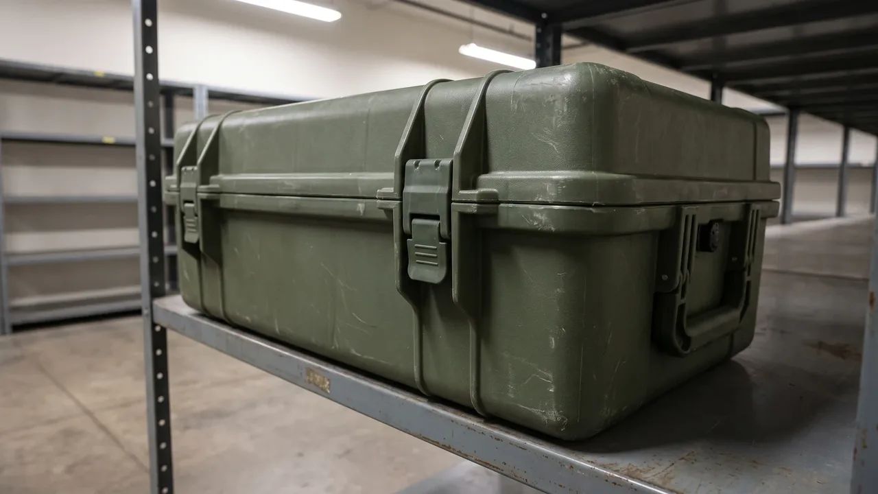
When the cargo being protected scales up from tens of kilograms to several hundred kilograms — or beyond a full tonne — a case stops being a shell and becomes a structure. The Heavy-Duty Protective Case exists for exactly this class of equipment: generator sets, hydraulic power units, optical mounts, and boxed spare-part modules that must survive forklifting, crane lifts, stacking, lashing, and thousands of kilometers of vibration while still opening clean at the destination. When JUNZHIJIA engineers a heavy-duty protective case for heavy-equipment manufacturers, defense-trade projects, and industrial transport operators, the first question is rarely material selection. It is load tracing: where does the force come from, which path does it travel, and where does it finally land. This article follows those two threads — structure and load — section by section, so that procurement and engineering teams can use it as a checklist when specifying, reviewing, or customizing a heavy case. For defense-trade and export scenarios, applicable local regulations and export-control requirements always prevail; this article discusses only the packaging container itself.
What Heavy Loads Change About Case Design
A standard protective case is designed around dust, water, and knocks. Once the payload becomes a power unit, a precision optic base, or a palletized module of spares, the design conversation shifts to structural strength and load management, and it shifts along three axes. Static load comes first: total mass — case plus contents — can run an order of magnitude above a consumer case, and the bottom box in a stack carries that weight continuously for months. Dynamic load comes second: crane sway, forklift acceleration, rail shunting impacts, and low-frequency ship rolling all generate inertia forces that scale directly with mass. Interface load comes third: lift points, fork pockets, and tow fittings stop being cosmetic hardware and become verified, load-rated structural members. Together these three shifts mean a heavy-duty protective case must be engineered the way a frame is engineered, not the way a container is decorated. Compared with a mid-range IP67 protective case, whose selling point is sealing, the heavy class must additionally publish numbers for stacking, lifting, and racking loads. Those numbers — and the tests behind them — are the subject of every section that follows. A fourth, quieter shift concerns service life: a heavy-duty protective case is purchased once and used for a decade across many campaigns, so abrasion, UV exposure, and repairability enter the specification alongside first-day performance, and the heavy-duty protective case that wins on paper is often the one that still seals and still lifts safely after its fifth year outdoors.
Managing Inertia: The First Problem of Large Masses
The inertia equation is brutally honest in transport engineering: double the mass and you double the force for the same acceleration. Road braking can generate one to two g. Rail shunting impacts run higher, and airdrop landing events must account for equivalent acceleration levels far beyond routine transport. Multiply any of these figures by several hundred kilograms and the result is a force measured in tonnes. The correct first response is not to make the case rigid; it is to give the equipment a controlled displacement envelope. Cushioning absorbs part of the impact energy, and restraint hardware takes over before the cushion bottoms out, preventing the payload from striking the case wall. Good designs keep two interfaces clearly separated: the cushion-restraint interface between equipment and case, and the isolation interface between the case and the transport environment, whether that is a damper pallet or an isolation mount. When the two act in series, their travel and stiffness must be staggered — if both reach their limits simultaneously, the shock passes through the entire load chain essentially unchanged. Rotation is the commonly missed dimension: when the payload center of gravity sits away from the geometric center of the cushioning, a linear impact adds an angular component, overloading one end while the other barely engages. The remedy is symmetric cushioning around the center of gravity, or auxiliary supports near CG height that hold rotation to a minimum. Combined-axis events complicate the picture further: vertical shock arriving during braking produces a resultant that lies between the two axes, so restraints are verified against the vector sum rather than each axis in isolation. One practical habit rounds out the analysis: log the real transport environment. A two-axis accelerometer riding along the first shipment tells the program what the route actually delivers, and that record replaces folklore with numbers when the design is later stretched to a heavier variant of the same payload.
Cushioning, Restraint, and Load-Sharing Frames
The most important internal partnership in a heavy-duty protective case is between the cushioning blocks and the load-sharing frame. The frame carries the equipment so that its weight never bears directly on the molded shell; loads are routed through engineered nodes into reinforced zones of the case body. Cushioning attenuates high-frequency shocks, while restraints intercept the residual load just before the cushion reaches full compression. The two jobs must not blur. Material behavior adds a thermal dimension: foam stiffness drifts with temperature, stiffening in deep cold and losing travel exactly when the shipment crosses a winter corridor, so cold-route programs need re-verification of dynamic stiffness at the lowest expected temperature. Restraint clearance also demands precision. Too much gap and the payload builds impact velocity inside the case; too little and the restraint engages before the cushioning has done its work. Unlike the general practice described for shock-absorbing protective cases, the heavy class is designed around the idea of permitted displacement: calculate the maximum excursion the equipment tolerates, then work backward to cushion thickness, foam grade, and restraint geometry. Rebound characteristics matter as well — closed-cell foams recover quickly for turn-around logistics, while slow-recovery grades absorb more energy per event and suit low-frequency, high-consequence shipments. Between frame and foam, load-spreader plates are worth their weight: without them, a hard restraint boss can dig a crater into the cushion block over repeated cycles, quietly converting a distributed interface into a point load.
Shell Cross-Sections and Rib Topology
Bending and torsional capacity in a heavy case shell comes from the combination of section depth, wall thickness, and rib layout. Rotational molding permits variable wall thickness and molded-in inserts, but rib geometry is constrained by draft and demolding: deep internal ribs that would help stiffness can trap the part. A sandwich construction — three-layer rotomolding with a foam core — buys a large jump in section inertia for very little added weight and is the usual route for heavy shells. In rib topology, orthogonal ribs divide large panels into small bays, raising local bending strength and suppressing oil-canning; generous corner radii keep stress concentrations from becoming crack initiation sites. Openings deserve their own discipline: pressure-relief valves, latches, and handle bosses must sit off the primary load-carrying ribs, and where an opening cannot move, the design compensates with local thickening or backing plates. Torsion deserves separate attention. A single-point lift or a sloped parking surface twists the box, and while a crossed rib grid resists bending admirably, torsional stiffness depends on continuous perimeter beams and diagonal corner bracing. Connecting the four side panels into one continuous load loop raises torsional rigidity markedly, and for precision payloads the planar stability of mounting surfaces under full load plus thermal cycling should be evaluated as part of the design review. A note on verification: section properties taken from CAD overstate real stiffness whenever weldlines, knit lines, or wall-thickness variation intrude, so heavy programs back the calculations with a simple cut-and-measure exercise on the first article, confirming actual wall thickness at the corners and ribs before the numbers are trusted.
Metal Frames and Rotomolded Composite Structures
A pure plastic shell has limited stiffness against tonne-class loads, so engineering practice converges on two composite routes. The first is the molded-in frame: steel or aluminum inserts are encapsulated inside the shell wall during rotomolding, so lift fittings, fork-pocket liners, and hinge mounts connect directly to metal. Plastic provides the seal and the corrosion face; metal carries the load. The second is the exoskeleton: a steel frame bolts to the outside of a rotomolded shell, the frame taking bending and torsion while the shell supplies the sealing boundary. Each route trades something. Molded-in inserts give a clean exterior and an unbroken sealing path with no through-fasteners, but every insert must be frozen before tooling is cut, so late redesign is expensive. An exoskeleton is easy to inspect, repair, and modify, yet every bolt hole is a potential leak path that needs gaskets, sealant discipline, and thread-locking practice. The image below shows the composite section of a molded-in frame design. Whichever route is chosen, the design file should state explicitly how load is shared between metal and plastic, because the alternative is a silent assumption that the other party is carrying the weight. Two further hazards belong in the drawing review: differential thermal expansion between steel and plastic cycling the insert region, and galvanic corrosion where dissimilar metals meet in salt-laden air. Both have standard countermeasures — rounded insert ends, generous plastic encapsulation, relief grooves on large inserts, insulating layers at dissimilar-metal joints — and both are cheap at the drawing stage and expensive in the field, which is exactly why they belong in the drawing review rather than the warranty file.
Load Paths Through Lift Points, Fork Pockets, and Tow Interfaces
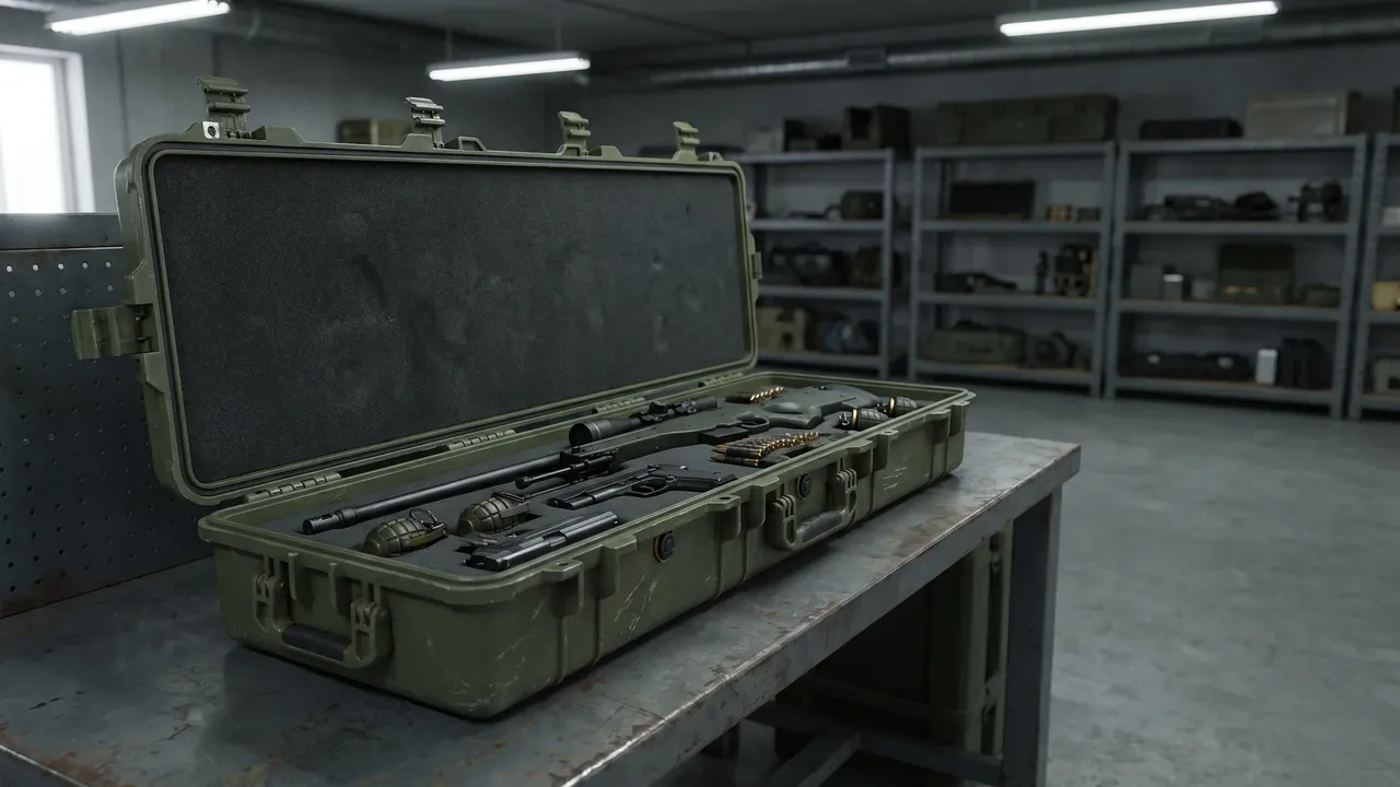
During a four-point crane lift of a Heavy-Duty Protective Case, the load path reads like a chain: equipment weight flows through the load-sharing frame into reinforced base nodes, then into the lift points, then out through the slings. One weak link fails the chain. Lift points are sized with a static safety factor — commonly four or five to one — and verified by pull testing in type testing; sling angle must be part of the calculation, because as the sling departs from vertical, each leg's load climbs toward and past half the total weight. Fork pockets must match the trucks that will actually use them: pocket height, width, and engagement depth sized with margin, and — the most common failure we see — the pocket liner tied into the frame rather than simply bonded to the shell floor. Tow interfaces operate in a different direction entirely: field towing loads them in horizontal shear, so they need independent verification even when they share hardware with lifting. When all three functions gather on one frame beam, that beam must be checked against the worst combination of lift, fork, and tow cases, with corrosion and wear allowances added. Layout also carries operational weight: lift-point spacing should match the spreader beams in service, fork pockets should pass fully through in matched pairs, and single-fork handling of a loaded case should be either verified as a case or banned in the operating procedure. Identification closes the operational loop: each lift point carries a permanent mark with its number and allowable load, the numbers map to current test records, and the rigger can confirm at a glance, before anyone hooks up, that the point is within its inspection interval. That traceability habit costs almost nothing at manufacture and pays for itself the first time two organizations share a loading dock.
Corner Feet, Anti-Slip, and Stacking Interfaces
In a stack, the bottom case carries everything above it, and its corner feet act as both compression members and alignment features. Mature designs use geometric interlock: the feet of the upper case seat into recesses molded into the lid of the lower case, so horizontal location comes from form, not friction. Feet in glass-fiber-reinforced nylon or rubber-capped steel carry the compression, with anti-slip tread patterns on the contact faces. The trap that catches most programs is creep. Thermoplastics deform slowly under sustained load, so a stack that passes a fresh compression test may be well past its real limit after a year in storage; permitted stack height must be checked against residual strength after creep, and long-duration war-reserve or spare-part storage is precisely where this matters most. The general principles echo those described for stackable cases and case stacking structures; the heavy-duty difference is that each layer weighs more, layer counts stay low, and every contact area must be verified against the heaviest layer at full load. Site conditions belong in the same calculation: uneven outdoor yards force torsion into the bottom case that no design assumed, so leveling plates or stacking frames are specified; warehouse aisles and forklift clearances are reviewed so a finished stack never becomes a collision hazard. Where stacks stand outdoors, UV exposure and rain change the calculation again: foot materials are chosen for weathering as well as compression, drainage around the stack base is planned so the bottom case never sits in standing water, and stack orientation follows the prevailing wind rather than fighting it.
Multi-Case Linking and Lashing
Convoy transport, deck stowage, and palletized shipment all ask several cases to act as one body. Linking hardware falls into three families — base latches, side pins, and perimeter frames — each with a natural role: latches for fast make-and-break, pins for precise location, perimeter frames for long-duration sea stowage. Lashing points are the interface between case and platform, and their duty differs by platform: deck lashing must survive multi-axis acceleration plus salt fog, while vehicle lashing must survive pretension decay under vibration, which argues for lock nuts or washers and a defined re-torque interval. Where lashing points are welded to frame members, weld quality and inspection access belong in the design conversation too, because a weld that cannot be seen cannot be inspected, and fatigue cracks announce themselves late. The layout rules mirror lift-point rules: short load paths, no lashing near shell openings, and anchorage into the load-sharing frame rather than the skin. Thermal movement is the detail most often omitted. Plastic cases expand and contract several times more than steel decks and brackets, so a long row of linked cases needs expansion gaps at defined intervals; otherwise temperature cycles build internal stress into latches and pins until the symptom appears as binding or cracking. Tolerance accumulation is the second practical trap: manufacturing variation compounds along a linked row, so location is concentrated at the ends and at segment breaks, mid-row connections carry adjustment slack, and the finished row is surveyed before shipment. Lashing hardware itself deserves a sentence of procurement care: forged shackles and pins carry traceable ratings, cast hardware of unknown provenance does not, and a lashing plan is only as good as the weakest fitting someone bought at the last minute. Document the assembled row as well — which case goes where, which faces mate, which latches engage — because a linked set that has been shipped once is far faster to re-assemble from a photo than from memory, especially when a different crew handles the return leg.
Sealing and Pressure Balance Under Heavy-Duty Service
The sealing logic of a Heavy-Duty Protective Case descends from its lighter siblings, but the duty is harsher. With a dense payload inside, free air volume shrinks, so the breathing effect of daily temperature swings drives real pressure differentials across a well-sealed enclosure — enough to distort gaskets and draw moisture through the weakest path, which is why a pressure-relief valve is standard equipment, not an accessory. Heavy service also flexes the whole box: a full case spanning two fork tines bends measurably, the sealing faces opening and closing by fractions of a millimeter, and the gasket section must have the compression set and recovery to follow. This is one reason heavy-case gaskets are deeper than consumer ones. Drainage must respect case attitude: if water does enter, floor channels should gather it to a defined low point away from the payload rather than pooling under the equipment. For long ocean stints, sealing and desiccation are treated as two independent lines of defense — a continuous gasketed boundary, then an internal humidity management layer of desiccant packs, humidity indicator cards, and a documented replacement interval. Each line is inspected on its own schedule, so a single defect never silently disables both. Gasket compound selection rounds out the section: dense elastomers seal well but take more closure force on a heavy lid, sponge grades conform easily but need protection from abrasion, and hybrid profiles combine a dense base with a soft bulb where the duty cycle demands both. Lid mass is the quiet variable in all of this — a heavy lid slamming shut on a poorly aligned hinge line chews gaskets quickly, so slow-close hinges, lid retainers, or simple opening-order labels extend sealing life more than any compound change. Testing the sealing system follows the same two-line logic: submersion or spray testing verifies the gasketed boundary, while a thermal cycling trial verifies that the pressure balance and drainage features keep working after the shell has flexed, breathed, and aged through the profiles it will meet in service. Related material selection — gasket compounds, aging behavior, and replacement cycles — follows the same reasoning set out for IP67-class sealing systems adapted to heavier hardware.
Out-of-Gauge Transport and Load Planning
Heavy equipment shipments frequently trigger out-of-gauge approvals, whether by weight, height, or width, so the case envelope is planned against the transport corridor: rail loading gauges, bridge and underpass clearances, container internal profiles, and aircraft door dimensions are checked one by one. The stowage plan should publish, per case, the weight, center-of-gravity height, fork-pocket positions, lift-point layout, and lashing-point coordinates, giving the carrier everything needed to engineer the securing plan instead of improvising it on the dock. Center-of-gravity management is the core of that plan. A high CG multiplies overturning moments, so the heaviest subassemblies are placed low in the case, light accessories ride high, and an external CG mark is applied per applicable labeling practice. Mixed loads add axle-weight allocation to the calculation so that neither the vehicle nor any single axle is over legal limits. Test intensity and distribution environment belong together in the same planning frame — the selection logic in the ASTM D4169 distribution cycle article links the planned corridor to the test levels the case must demonstrate. Where the out-of-gauge class becomes prohibitive, splitting the equipment into two shipping units with dedicated interface protectors, alignment datums, and traveling tooling can be the cheaper overall route; whether it is depends on approval cost, corridor availability, and field assembly conditions. One more planning detail earns its keep: publish the permissible tug and push loads on the case exterior, because harbor tugs, pushers, and winching operations all apply loads the stowage plan never mentioned, and a small printed rating on the shell turns a guess into a procedure. Shippers who share the corridor data — draft surveys, bridge surveys, ferry schedules — let the packaging engineer close the loop between planned environment and tested strength, which is the whole point of planning.
Heavy-Duty Test Matrix: Compression, Drop, Vibration, and Bogie Impact
From a manufacturer's standpoint, type testing for the heavy class normally consists of four blocks, and together they form the qualification backbone of any Heavy-Duty Protective Case program. Compression: a sustained load held for twenty-four hours or longer, watching for deflection that exceeds allowance — this is where long-duration structure and creep are proven. Drop: height is set by transport mode and weight class, following the correspondence tables summarized in the drop height by weight guide; unlike lighter cases that favor flat-face drops, heavy programs concentrate on edge and corner orientations, because those are the attitudes where energy lands on the smallest contact area. Vibration: a sine sweep first locates resonances, then random vibration accumulates fatigue damage, with the load-sharing frame and restraints checked for loosening and migration after the run. Bogie impact: the horizontal shock of rail shunting, aimed at the case body and the lashing interfaces in their true directions. Sequence follows the distribution environment — static before dynamic, single axes before combinations. The acceptance definition is twofold: equipment undamaged and case reusable. A case that cracks but saves the payload is only half a pass, because reusability is the economic floor of the category. The test plan should also fix sample count, post-test teardown inspection, and the batch sampling rate for production, since a report valid for one prototype is weak evidence for a running batch after a tool or resin change. Pre-production instrumentation is a small extra with a large return: strain gauges on the frame nodes and accelerometers on the payload during development tests reveal where the real margins sit, and those same channels become the acceptance baseline that production samples are later compared against. Where a program runs multiple shell sizes, commonality is worth engineering deliberately: shared frame nodes, shared foot geometry, and shared interface hardware across the size range simplify spares, simplify training, and make the test evidence of one size at least partly reusable for its siblings, under a delta argument agreed with the acceptance authority rather than assumed.
Acceptance Criteria: From Test Data to Release
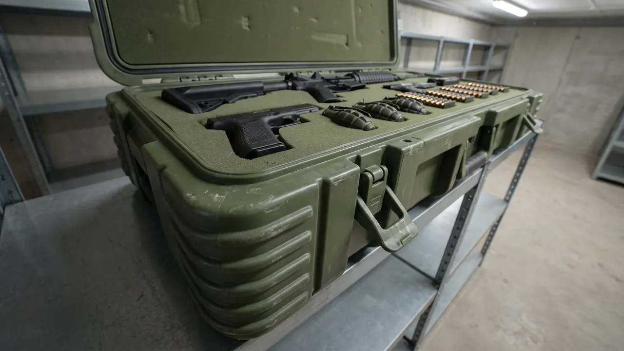
Turning test data into enforceable acceptance clauses starts with a technical agreement that states at least five items: the standard identifiers and versions, test levels and directions, specimen condition, pass criteria, and re-verification rules. Specimen condition is the clause most often left vague. Real-equipment testing is expensive, so equivalent dummy payloads are substituted — but a good dummy reproduces the payload's mass distribution and structural stiffness, not just its weight, because stiffness changes the restraint travel and cushion response entirely, and a rigid steel block will pass a test the real assembly would fail. Military-standard frameworks are covered in the GJB military standard case article; industrial distribution environments can adapt the methods in the stacking load test article. Acceptance should also include batch sampling and disposition rules for failed lots, closing the classic gap where a prototype passes and production drifts, and every published rating on the heavy-duty protective case — stacking, lifting, forking, lashing — should trace to a line in the test report, closing the distance between brochure and evidence. Documentation closes the loop: raw test data, material batch certificates, and material certificates for critical metalwork are indexed to case serial numbers, forming a traceable archive. When transport damage surfaces years later, that archive distinguishes a structural failure from an operational overload, and it feeds real numbers back into the next design iteration instead of anecdote. A final clause worth negotiating early is disposition of test articles: cases that survive type testing can often be refurbished and entered into the training or demonstration pool, which recovers part of the testing cost and gives new handlers a physical artifact to inspect before the real shipment ever leaves the yard.
Service Life Maintenance and Refurbishment
A heavy-duty protective case is normally a ten-year-plus asset, so its maintenance plan should be written into the equipment's support cycle rather than improvised. Interval-based items include gasket elasticity and compression-set checks, hinge and latch lubrication, fastener re-torque, visual aging inspection of cushioning, and dimensional re-checks of lift points and feet. Condition-based items include periodic compression and vibration spot tests per batch, corrosion repair of frame members, and functional testing of pressure valves. Refurbishment triggers follow condition, not calendar: crushed cushioning, through-cracked shells, or permanently deformed sealing faces each put a case into the refurbishment lane, where structural members are restored first and cosmetics follow budget. Two economic arguments deserve a place in the review. First, maintenance records are asset records: a case with a complete inspection and refurbishment file commands a materially better residual value in resale, rental return, or redeployment. Second, once annual maintenance is amortized over the service life, the higher-quality case frequently shows the lower total cost — the structural redundancy and testing paid for at purchase are what the maintenance plan is preserving. A short annual review against the original load ratings completes the cycle, catching slow capability erosion before it becomes a transport incident. Training belongs in the same plan: the handlers who open, lift, and stack the case daily benefit from a one-page service card — allowable lift configurations, stack ratings, valve maintenance, opening sequence — because most field damage we see traces to a well-intentioned improvisation the design never anticipated.
Selection and Customization Checklist
At project start, procurement and engineering should jointly confirm one input list: maximum equipment envelope and total weight, center-of-gravity position, operating and transit temperature range, distribution routes across road, rail, sea, and air, permitted stack count and expected storage duration, the forklift and crane models actually available at both ends, lashing interface standards, opening frequency and on-site tooling, and marking or traceability requirements. Each input drives structure directly: temperature range selects cushion and gasket compounds, distribution routes select the test matrix, stacking rules size the feet and shell sections, and handling equipment shapes the fork pockets and lift points. One addition pays for itself: a short history of problems with the previous case generation, even anecdotal, lets the designer land improvements exactly where the pain was. JUNZHIJIA's custom heavy-duty protective case process starts from this list — load cases first, then structure, then quotation — because change orders late in tooling cost multiples of the conversation that would have prevented them. The image below shows a typical fork-pocket and lift-point arrangement at the case base. For defense-trade and export contexts, the comparisons in the military protective case selection article pair well with this checklist. Finally, agree on a change-control rule: any later change to payload weight, distribution route, or handling equipment is routed back to the case designer for a delta review, because a heavy-duty protective case is a system of ratings that move together, and silent unilateral changes are how sound designs drift into unsafe ones. Treating the case as a rated system, reviewed with the same discipline as the payload itself, is the cheapest insurance a heavy program can buy.
Frequently Asked Questions
Q: What structurally separates a heavy-duty protective case from an ordinary tool case?
A: The difference is not thicker walls; it is a migration of design objectives. An ordinary tool case is organized around containment and scuff protection, with structural checks limited to handles and hinges. A heavy-duty protective case is engineered as a load-bearing structure: the shell section, ribs, lift points, fork pockets, and corner feet each carry a defined load case with a stated safety factor, stacking, lifting, and lashing each form an independent load path, and the whole assembly is validated through a matrix of compression, drop, vibration, and horizontal impact testing. It helps to look at the consequence of failure. A broken hinge on a tool case is an inconvenience; a failed lift point on a heavy case can destroy a complete assembly and injure the lifting crew. That asymmetry is why material selection, structure, and acceptance all follow structural-engineering practice rather than container practice, and why the price includes deliberate redundancy and type testing. When you compare quotations, that structural scope — load cases calculated, paths verified, tests performed — is the real boundary between the two categories, and it is where most of the cost difference lives.
Q: Which suits a large payload better, a rotomolded shell or a metal shell?
A: Each owns a different region of the problem. A rotomolded shell with molded-in metal inserts, or combined with an external frame, normally covers load requirements up to the several-hundred-kilogram class. Its advantages are corrosion resistance, a genuinely sealed enclosure, easier repair, and lower cost in volume — which is why it dominates salt-fog shipping lanes and humid storage. A metal shell holds the advantage above roughly a tonne, in high-temperature service, and where lifting is frequent enough that stiffness and heat resistance dominate the duty cycle; the trade is higher weight, longer fabrication, and difficult field repair of damaged panels. The practical method is to rank four variables before choosing: maximum payload, extreme temperatures, corrosion environment, and budget. Most projects should fix the load cases first, then check sealing and corrosion needs, then compare price — selecting by material allegiance alone tends to buy either more case than needed or the wrong one entirely. The composite routes described in the frame and shell sections of this article usually dissolve the apparent either-or choice into a mix: plastic where sealing and corrosion matter, metal precisely where the load path runs.
Q: When the payload changes to a heavier model, how should cushioning and restraint be redesigned?
A: Start from the energy. Multiply the new mass by the design impact velocity to get the energy the system must absorb, then check where the existing cushion operates on its stress-strain curve — a heavier payload almost always pushes the foam past its efficient range, exhausting its travel early so the restraints bottom out and the shock bypasses the cushioning entirely. That bypass is the classic mechanism behind damage on first shipments of an upgraded model. Common corrections include a higher-density foam grade, thicker cushion sections, or redistributed block positions so pressure spreads evenly; restraint clearances are then re-set so the restraints engage only as the cushion nears its limit. Two structural checks ride along with the cushion work. Lift points and corner feet were rated for the original weight, and their loads scale up with the payload even if the case is untouched, so each rating must be re-verified, along with the load-sharing frame nodes. Finally, repeat drop and vibration testing with a new dummy that matches the new mass distribution — old reports are invalid once weight and its distribution change, because resonance frequencies and attitude responses both move.
Q: Can lift points and fork pockets share one load path?
A: Yes, provided the shared beam is designed for the worst combination of the individual cases. Lifting loads the structure in near-vertical tension, forking in local compression and bending with a two-point support, and towing in horizontal shear — different magnitudes, directions, and application points. When all three interfaces converge on one frame beam, calculate the internal forces for each case separately, then size the beam for the governing combination with margin added for corrosion and wear. Just as important, the loads must actually reach the load-sharing frame rather than terminating in the shell wall, which is where shared interfaces most often fail in service. The payoff for sharing is weight and layout simplicity; the price is more verification work. In practice, we recommend that drawings label every interface with its design case and allowable load, that type testing exercise each case separately, and that any combination not individually tested be excluded from the technical agreement. A shared load path is a legitimate, space-efficient design — as long as its paperwork is as complete as its structure, and as long as the shop floor never relocates an interface without the same review that placed it there in the first place.
Q: How is the permitted stacking count determined, and on what test?
A: Stack height is set by the capacity of the bottom case, not by a supplier's assurance. The calculation starts from the combined full-load weight of every case above, multiplied by a dynamic factor that covers transport and handling increments. The supporting test is a sustained-load compression run: the stack load is applied for at least twenty-four hours while deflection is monitored for continued growth and the feet and locating recesses are inspected for local yielding. For long storage periods, creep behavior enters the judgment — thermoplastics keep deforming slowly under constant load, so permitted height should be based on residual strength after the storage duration, not on the fresh-out-of-tooling test result. Temperature is a live variable too, because elevated storage temperatures materially reduce the load capacity of plastic sections, and hot-climate warehouses are exactly where stacks stand longest. We recommend that the technical file bind three things together — permitted layer count, applicable temperature range, and maximum storage duration — and treat the trio as a single rating. A stack height quoted without those two companions is not a specification; it is a hope.
Q: What information must the case supplier provide for out-of-gauge transport?
A: At minimum, five groups. First, external dimensions and gross weight, which drive the out-of-gauge classification and route planning. Second, the center-of-gravity position and its external marking, which the carrier needs for securing calculations and axle allocation. Third, fork-pocket and lift-point positions, dimensions, and allowable loads, so the handling equipment at each end can be selected without guesswork. Fourth, lashing-point coordinates and the allowable pull at each point, which are the direct inputs to the securing plan. Fifth, stacking permissions and prohibitions — orientation limits, top-load allowances, and whether the case may be placed on end. Deliver the information as drawings or data sheets rather than conversation, and add a gauge-clearance conclusion for each leg when the move is intermodal. The cooperative mechanism matters as much as the documents: if the carrier's securing plan demands loads or attitudes beyond the published ratings, the case designer should review the deviation before transport, rather than the crew improvising on site. That review loop is inexpensive, and it is precisely the step whose absence turns an out-of-gauge move into an incident report.
Q: How are drop height and orientation specified in heavy-duty testing?
A: Drop height is derived, not guessed: transport mode sets the baseline — air and rail requirements typically exceed road — and within a mode, heavier weight classes are assigned lower heights, with each standard publishing the correspondence table. Orientation is the half of the specification that gets skipped: a complete program covers flat-face, edge, and corner orientations, and for heavy cases the edge and corner attitudes are the demanding ones, because impact energy concentrates on the smallest contact areas, while the flat-face orientation chiefly probes panel bending. Execution follows the standard's prescribed sequence and repetition count, with each attitude landing on a different edge or corner so the whole periphery is exercised. Cases riding on isolation pallets or damper bases need the base evaluated in its own orientations and travels, since the base changes the impact signature entirely. The pass judgment is twofold — equipment functional and case reusable — and any omitted orientation must be recorded as a documented deviation with its rationale in the report. A drop program that quietly drops the corner orientations has not tested the case you will actually ship; it has tested the one you wanted to sell.
Q: What inputs does a custom heavy-duty protective case require?
A: A complete input list covers the equipment envelope and total weight, center-of-gravity position, temperature range, distribution routes and transport modes, permitted stacking and storage duration, the handling equipment models at both ends, lifting and lashing interface standards, opening frequency, sealing requirements, and marking needs. Each input lands on a specific design decision: temperature range selects cushion and gasket compounds, distribution routes build the test matrix, stacking rules size the feet and shell sections, and the handling fleet shapes fork pockets and lift points. If some items are undecided, lock down at least weight, center of gravity, and distribution routes, because those three dominate structural cost — a change in any of them ripples through frame sizing, test planning, and interface hardware. We also ask for the history of the previous case generation: even one line about where the old case failed or annoyed its users lets us aim the improvements precisely. Any supplier who quotes directly from an outline dimension without a load-case analysis is leaving the expensive surprises for later; one extra conversation up front is always cheaper than a tooling change.
The pointers below lead to related reading on this site:
Closing
Heavy-duty protection is load tracing, end to end. Write the load cases first; the structure and the price will follow.