

A coordinate measuring probe is calibrated at the factory, loaded onto a truck, driven over speed bumps, lifted thirty centimetres by a forklift and set down again, then unpacked at the customer site. Nobody shouts "handle with care" at any point, yet the instrument must arrive undamaged. What decides the outcome is rarely whether foam is present; it is how thick that foam is, how stiff it is, where it bears load, and how much energy the shell absorbs before the liner ever compresses. Shockproof design is fundamentally energy management: the energy released by a drop must be spread, stretched in time and dissipated so that peak acceleration reaching the payload stays below its fragility.
JUNZHIJIA's position on shockproof protective cases is this: cushioning is not a matter of adding thickness, but of matching the stress-strain behaviour of the cushion material to payload fragility, weight and bearing area, then distributing the required stopping distance across three structural levels, namely the shell, the skeleton and the liner. That principle underpins every selection table and acceptance criterion below.
Table of Contents
- What an Impact Load Really Is: From Drop Energy to Product Fragility
- The Core Design Tool: Cushion Curves and Static Stress
- Choosing Cushioning Materials: Dynamic Behaviour of EPE, EVA, PE and IXPE
- Multi-Level Cushioning: Energy Split Between Shell, Skeleton and Liner
- Impact Isolation: The Logic of Floating the Payload
- Energy Concentration at Corners and Edges: Local Reinforcement
- Liner Tooling and Compartments: Putting Thickness Where It Matters
- Stacking, Drop and Vibration: How Transport Testing Validates Cushioning
- How Environmental Ageing Degrades Cushioning Performance
- Shell Material and Structural Stiffness: Why the Shell Must Not Be Too Soft
- Latches, Hinges and Secondary Impact: Closure System Reliability
- Frequently Asked Questions FAQ
- Conclusion and Related Reading
What an Impact Load Really Is: From Drop Energy to Product Fragility
The first step in shockproof design is quantification, not material selection. A case of mass m falling from height h arrives with kinetic energy close to mgh and an impact velocity of the square root of 2gh. At 60 cm the contact velocity is about 3.43 m per second, and that velocity must fall to zero within a very short distance. The shorter the distance, the higher the deceleration and the larger the inertial force on the payload. All the value of a cushion lies in stretching this deceleration distance from a few millimetres to tens of millimetres.
The upper acceleration a product can survive is its fragility or damage boundary, normally expressed in G. It is not a material constant but a threshold for one specific product under one failure criterion: a glass panel may crack at 30 G, a ruggedised laptop may survive 80 G, and the sensitive axis of a precision gyro may lose calibration at 15 G. ASTM D3332 defines procedures for determining it. In practice a stepped shock machine test is more common, raising peak acceleration level by level until function is lost, taking the last passing level as design fragility and applying a safety factor of 0.6 to 0.8.
Real logistics impacts are rarely clean free drops. Throwing during loading, conveyor bounce, truck bed vibration and air freight touchdown differ in waveform and duration. Short impacts mainly excite local deformation and justify a higher fragility estimate; longer ones excite global modes and must be treated conservatively. JUNZHIJIA asks for three numbers at design review: payload weight, available bearing area, and fragility or an agreed substitute criterion.
| Payload Category | Typical Fragility (G) | Dominant Failure Mode | Recommended Cushioning Approach |
|---|---|---|---|
| --- | --- | --- | --- |
| Precision optics, interferometers | 15 - 30 | Axis shift, coating cracking | Low static stress thick foam plus global isolation |
| Inertial sensors, gyros | 20 - 40 | Axis misalignment, solder cracking | Full enclosure thick liner plus corner reinforcement |
| Medical diagnostic modules | 30 - 50 | Connector loosening, display cracking | Compartmented fixing plus medium static stress |
| Ruggedised laptops, tablets | 50 - 80 | Screen breakage, drive damage | Four-corner support plus edge restraint |
| Power tools, hand instruments | 80 - 120 | Housing cracking, edge chipping | Grid locating plus abrasion resistant liner |
The Core Design Tool: Cushion Curves and Static Stress
The cushion curve is the single most important chart in shockproof design. The horizontal axis is static stress, the vertical axis is peak acceleration transmitted to the product, in G, and each curve corresponds to one material, one thickness and one drop height. Static stress is simply payload weight W divided by the bearing area A pressing on the cushion, sigma equals W over A, usually in kilopascals. The method is to compute static stress, read peak acceleration from the matching curve, and confirm it sits below product fragility.
The curve is U-shaped because two failure mechanisms dominate at opposite ends. When static stress is too low the cushion barely compresses, apparent stiffness is high, energy is not absorbed in time and peak acceleration rises again. When static stress is too high the cushion bottoms out and the remaining energy is delivered through a nearly rigid path, which also drives the peak up. The trough is the optimum working point, and good practice places the design point slightly to the right of it so a heavier payload than expected does not immediately fall into the bottoming region.
Thickness is the second key variable. At a given drop height, increasing thickness shifts the whole curve downward and moves the trough left, giving lower peak acceleration and a smaller permissible bearing area. This is why precision instrument cases are bulky: thickness is not padding, it is the physical carrier of stopping distance. It cannot grow without limit though, because outer dimensions and freight cost rise with it, so JUNZHIJIA specifies the smallest thickness that keeps peak acceleration below 0.8 times fragility.
| Drop Height | Impact Velocity (m/s) | Energy per kg (J) | Typical Scenario | Suggested Margin |
|---|---|---|---|---|
| --- | --- | --- | --- | --- |
| 30 cm | 2.43 | 2.94 | Bench handling, hand transfer | 1.2x |
| 45 cm | 2.97 | 4.41 | Conveyor drops, trolley loading | 1.3x |
| 60 cm | 3.43 | 5.88 | Forklift tine lowered | 1.4x |
| 90 cm | 4.20 | 8.82 | Tail lift drops, rough handling | 1.5x |
Drop height and drop count must also be included. Curves are published in bands of 30, 45, 60 and 90 cm, and doubling height doubles the energy to absorb. Repeated drops bring cumulative damage, so reusable cases must be specified on multi-drop performance.
Choosing Cushioning Materials: Dynamic Behaviour of EPE, EVA, PE and IXPE
Material choice cannot rest on softness alone. Cushioning capability comes from three mechanisms: cell wall buckling, compression and rebound of gas trapped in closed cells, and viscoelastic dissipation in the polymer. Open-cell materials let gas escape, so they recover slowly and take permanent set. Closed-cell materials trap gas and behave like a mattress of tiny air springs, giving fast recovery and good multi-impact resistance, but they are rate sensitive.
EPE, expanded polyethylene or pearl cotton, is the highest volume cushioning material. Its cells are largely independent, density normally falls between 20 and 40 kilograms per cubic metre, resilience is good, water absorption is negligible and chemical resistance is excellent at a controllable price. Its weakness is creep: under sustained load it loses thickness, so it suits the main energy absorbing layer rather than a precision locating layer.
EVA covers 50 to 250 kilograms per cubic metre, offers high elasticity, good tear strength and a fine surface, and is preferred for CNC routed or compression moulded precision liners. It holds recovery over repeated impacts and is more dimensionally stable than EPE, though it absorbs less energy per unit thickness and high density grades add weight. IXPE, irradiation cross-linked polyethylene, has a fine uniform cell structure and compression set as low as 2 to 6 percent, suiting long service cases. PU sponge is soft but open-celled, slow to recover and hygroscopic, so it serves as a facing rather than the primary cushion.
| Material | Density (kg/m3) | Strength (kPa) | Resilience (%) | Compression Set (%) | Service Temp (C) | Strength and Weakness |
|---|---|---|---|---|---|---|
| --- | --- | --- | --- | --- | --- | --- |
| EPE standard | 20 - 40 | 60 - 140 | 85 - 92 | 8 - 15 | -40 to 80 | Efficient, low cost; modest creep resistance |
| EPE high density | 45 - 70 | 160 - 280 | 80 - 88 | 6 - 12 | -40 to 80 | Good load bearing; lower efficiency |
| EVA foam | 50 - 150 | 120 - 500 | 88 - 95 | 5 - 10 | -30 to 70 | Stable, routable; heavy |
| EVA high density | 180 - 250 | 600 - 1100 | 85 - 92 | 4 - 8 | -30 to 70 | Precise locating; short stroke |
| IXPE cross-linked | 30 - 100 | 100 - 350 | 90 - 96 | 2 - 6 | -50 to 90 | Best compression set; higher price |
| PE foam | 25 - 60 | 80 - 200 | 82 - 90 | 10 - 18 | -40 to 80 | Versatile; average recovery |
| PU sponge | 20 - 60 | 40 - 150 | 60 - 80 | 15 - 30 | -20 to 70 | Soft; absorbs moisture, ages |
Multi-Level Cushioning: Energy Split Between Shell, Skeleton and Liner
Handing the whole cushioning task to liner foam is the most common design error. A more robust approach splits absorption across three levels. The shell spreads a concentrated impact into a distributed load and absorbs a modest share through its own elastic deformation. The skeleton and ribs form the second level, controlling deformation mode and preventing local instability. The liner foam carries most of the compression stroke and is the true energy absorbing body.
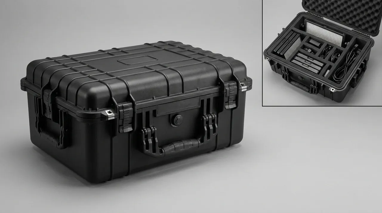
A rotationally moulded PE shell of 3 to 6 mm wall can deflect several millimetres locally under a corner impact, stretching the peak from a few milliseconds to over ten, which alone shaves twenty to thirty percent off peak acceleration. Injection PP shells are stiffer and deform less, so their energy contribution is limited, but they deliver better stacking stability and accuracy. On mid and large cases JUNZHIJIA pairs a rotationally moulded shell with an internal skeleton.
The skeleton consists of ribs, carrier plates and restraining frames. Its job is locating rather than cushioning: it keeps the liner from shifting during impact and stops load concentrating into one corner. Materials are usually PP or ABS sheet, or aluminium extrusion fixed by slots or ultrasonic welding. Skeleton stiffness must be significantly higher than liner stiffness, otherwise the two form a series-parallel spring system and effective stroke becomes unpredictable.
The critical liner parameter is usable stroke. With thickness T and a maximum usable compressive strain of 60 to 70 percent, beyond which the material densifies and stiffens sharply, usable stroke is about 0.6 T. Energy conservation with a uniform deceleration approximation gives stroke s approximately equal to v squared over 2a. At 60 cm, v is 3.43 m per second and a 30 G target means a of about 294 m per second squared, so s is near 20 mm and minimum thickness near 33 mm.
| Level | Function | Typical Material | Energy Share | Key Parameters |
|---|---|---|---|---|
| --- | --- | --- | --- | --- |
| Shell | Spread load, absorb, protect | Rotomoulded PE, PP, aluminium | 10 - 25 percent | Wall thickness, corner radius, rib spacing |
| Skeleton | Locate, restrain, control mode | PP sheet, ABS sheet, extrusion | 5 - 15 percent | Stiffness, fixing points, clearance |
| Liner | Main absorption, peak control | EPE, EVA, IXPE | 60 - 85 percent | Thickness, density, bearing area, strain |
Impact Isolation: The Logic of Floating the Payload
Cushioning and isolation are often confused although their objectives differ. Cushioning addresses single, high amplitude, short duration transient shocks, measured by whether peak acceleration stays below fragility. Isolation addresses continuous, low amplitude, broadband vibration, measured by whether transmissibility drops below one so the payload sees less motion than the vehicle.
Isolation theory rests on the transmissibility curve of a single degree of freedom system, where natural frequency fn equals one over two pi times the square root of stiffness divided by mass. When the ratio of excitation frequency to fn is below the square root of two, transmissibility exceeds one and the isolator amplifies motion; only above that ratio does it fall below one, improving as the ratio grows. Lowering fn means lowering stiffness, since mass is fixed, and lower stiffness means larger static deflection, which happens to align with the stroke requirement of cushioning. Thick foam therefore delivers isolation as a by-product.
The practical constraint is that static deflection, mg over k, must stay reasonable or the payload sinks and tilts. The usual rule is to hold it between 3 and 8 mm and back-calculate stiffness. For truck transport the dominant excitation energy lies between 2 and 20 Hz, so pushing fn below 8 Hz demands quite low support stiffness, generous bearing area and low material density.
Foam also supplies viscoelastic damping with a loss factor typically between 0.05 and 0.2, which suppresses resonant amplification and is a genuine advantage over metal springs. Designers should keep system natural frequency out of the 2 to 10 Hz main excitation band and add damping layers when that is impossible. For heavy payloads JUNZHIJIA combines full-area foam support with four metal snubbers that take over at extreme load so the payload never strikes the floor after foam crush.
Energy Concentration at Corners and Edges: Local Reinforcement
Of all drop orientations, corner drop is the most severe. Contact area is minimal, the same energy concentrates into a tiny region, local shell strain peaks, and effective liner thickness at the corner is usually reduced by the corner radius and assembly clearance. Both ISTA and GB/T 4857 mandate corner drops because field experience says so.
The first countermeasure is geometric: a large corner radius or spherical transition turns point contact into small-area contact and lowers local strain. The second is local thickening, raising wall thickness by 30 to 50 percent in the corner region or adding radial ribs that spread load along two edges and three panels. The third is liner compensation, reserving extra cushion thickness at corners or creating a relief cavity so the payload never presses on the weakest point of the liner corner.
Edges matter too. A long edge struck in a drop carries a bending wave that travels along it, reflects at the ends and superimposes, potentially producing high strain far from the contact point. Interrupted ribs and edge cushion strips such as closed-cell EPDM profiles break the propagation path. On long narrow cases JUNZHIJIA runs continuous cushion strips along all four edges plus transverse ribs every 200 to 300 mm.
| Drop Orientation | Contact Character | Local Stress | Liner Requirement | Typical Reinforcement |
|---|---|---|---|---|
| --- | --- | --- | --- | --- |
| Flat drop | Large area | Low | Uniform bearing sufficient | None special |
| Edge drop | Line contact | Medium | Add 20 percent at edges | Edge strip, transverse ribs |
| Corner drop | Point contact | Highest | Relief cavity, thicker cushion | Large radius, radial ribs, corner caps |
| Rotational drop | Multiple impacts | Medium to high | Effective cushioning all faces | Full enclosure liner, tough shell |
Liner Tooling and Compartments: Putting Thickness Where It Matters
Even the best material is wasted if cushion thickness does not sit under the most fragile part of the payload. Liner design comes down to three decisions: bearing area, cushion thickness and restraint method.
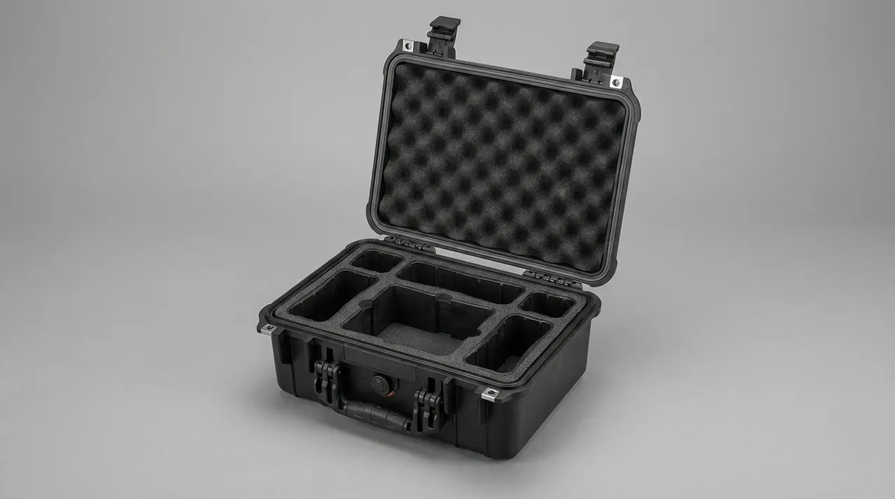
Bearing area sets static stress. Product bottoms are rarely flat; they have feet, bosses and connectors, so the area that genuinely carries load may be a few small patches. A bearing map is essential: press the payload onto pressure indicating film to find real contact regions, and if effective area is too small, add a carrier plate or shape the cavity floor to spread load. Slender items such as lenses or probes are better gripped by two mating blocks using side friction.
Thickness follows from the calculation above and must be checked in the worst orientation, confirming for every drop direction that at least the computed usable stroke exists between payload and shell. Top cushioning is often overlooked: in a flat drop the top liner carries load too, so a case with 40 mm at the bottom and 10 mm at the top fails when inverted.
Restraint method determines whether the payload moves. A fully enclosing cavity locates most reliably but is tolerance sensitive. Pick and pluck cubed foam, described in Pick and Pluck Foam Cases, is flexible and cheap for tools of varying shape. CNC routed EVA gives the highest accuracy for instruments; compression moulded EVA suits stable volume products. JUNZHIJIA supports both routes through the EVA Foam Insert Custom Process. Cavity clearance of 0.5 to 1.5 mm aids removal, and parts above 2 kg need a hand grip position.
| Liner Process | Accuracy | Suitable Volume | Unit Cost | Typical Use |
|---|---|---|---|---|
| --- | --- | --- | --- | --- |
| Pick and pluck cubes | plus minus 3 mm | Very small batches | Low | Tool and demo cases |
| Hand cut and fitted | plus minus 2 mm | One-off prototyping | Medium | Sample validation |
| CNC routed EVA | plus minus 0.3 mm | Small to medium | Medium high | Instruments, optics |
| Compression moulded EVA | plus minus 0.5 mm | Medium to large | High tooling, low unit | Volume products |
| Multi-layer EPE laminate | plus minus 2 mm | Any | Low to medium | General transit |
| Thermoformed tray | plus minus 0.2 mm | Large batches | High tooling | Component handling |
Stacking, Drop and Vibration: How Transport Testing Validates Cushioning
Whether a design works is settled by test. The widely used protocols are the ISTA series 1A, 2A, 3A and 3E, ASTM D4169 and the GB/T 4857 series. All follow the same logic: condition the package, then drop, stack and vibrate it, then inspect product and packaging.
Drop height is graded by weight. Under ISTA 1A, packages below 9.5 kg drop from about 762 mm, those from 9.5 to 18.6 kg from about 610 mm, and those from 18.6 to 27.7 kg from about 457 mm, decreasing further for heavier items. Orientations cover the base, one corner, three edges and the remaining faces, roughly ten drops. GB/T 4857.5 is similar and allows agreed alternative heights. JUNZHIJIA recommends selecting a level one step above the customer's actual distribution environment rather than automatically taking the lowest grade.
Stacking examines deformation under sustained load: a load equivalent to the intended stack height is applied to the top face and held from 24 hours to 28 days, with deformation and recovery measured. For liner foam this is really a creep test, since EPE under high temperature and humidity can lose over 10 percent thickness, and a design stroke already at its lower bound becomes insufficient afterwards.
Vibration comes in sinusoidal and random forms. Random vibration resembles real transport and is described by power spectral density; a typical truck spectrum decreases in energy from 1 to 200 Hz at roughly 0.4 to 0.7 g overall RMS, with duration scaled to distance. The threat is cumulative: connectors loosen, screws back off, liners abrade and lose locating ability, and foam heats and softens. See Toolbox Durability and Load Testing.
Acceptance criteria must be agreed in writing before testing. JUNZHIJIA's standard criteria are: payload passes powered self-test with a log, no new structural cracks, permanent liner compression not over 10 percent of original thickness, no penetrating shell damage, and latches and hinges functioning. The criteria should also state whether repair and retest is permitted.
How Environmental Ageing Degrades Cushioning Performance
A cushion is not a constant spring. Its modulus changes with temperature, humidity and time, and a design based only on room temperature virgin data can differ from field results by a factor of two between winter and summer.
Temperature dominates. EPE and EVA are semi-crystalline polymers; at low temperature chain mobility is restricted, the material stiffens, compression strength rises, cushioning efficiency falls and peak acceleration increases, while at high temperature the material softens and bottoming becomes more likely. The datasheet service range defines where irreversible damage does not occur, not constant performance. Plateau field work combining altitude and cold deserves dedicated low temperature drop validation, as covered in Outdoor Cases at High Altitude.
Compression set is the other critical indicator, measured to ASTM D3575 or GB/T 6669: compress the specimen to 50 or 75 percent, hold normally 22 hours, release and measure recovery. IXPE can reach 2 to 6 percent while ordinary PE foam may reach 10 to 18 percent, and for cases kept loaded or stacked this figure directly sets liner service life.
Humidity and salt spray mainly attack metal parts. Hinges, latches and rivets corrode under neutral salt spray to GB/T 10125, and the corrosion products expand and seize moving parts so they cannot deform and absorb energy during impact. Metal isolators should be stainless steel or finished with dacromet or zinc-nickel. Foam absorbs almost no moisture, but damp heat accelerates surface oxidation, so low-outgassing grades are required in medical and semiconductor work. Accelerated ageing at 70 C with Arrhenius extrapolation is the usual life prediction tool, and JUNZHIJIA supplies 500 hour data for long service cases.
Shell Material and Structural Stiffness: Why the Shell Must Not Be Too Soft
The shell must be neither too soft nor too hard. Too soft and it deforms heavily under impact, possibly pressing on the payload or removing effective liner stroke. Too hard and it absorbs nothing, handing all energy to the liner, and it may crack in a brittle manner. The ideal behaviour is to hold shape under service loads, preserving stacking and sealing, and to undergo large but fully recoverable deformation under extreme impact.
Rotationally moulded polyethylene is the classic shell material: uniform wall thickness, no weld lines, natural material build-up at corners acting as built-in reinforcement, and impact toughness retained at low temperature. Disadvantages are dimensional accuracy of only about plus minus 1 to 2 percent and a finish inferior to injection moulding. Injection PP offers high accuracy, good surface and complex ribs, but weld lines are weak points and low temperature toughness depends on copolymer modification.
Aluminium shells are stiff and dimensionally stable but absorb almost no energy, so the liner handles everything, and any plastic deformation is permanent, later compromising sealing and stacking. Aluminium suits rigid protection and precise locating, as in the products discussed in Instrument Cases. PC/ABS balances stiffness and toughness for small and medium precision cases. Across the Rotomoulded Protective Case range JUNZHIJIA combines an outer crown with internal ribs to balance impact resistance and stacking deformation.
Structural stiffness comes from wall thickness, ribs and curvature. Rib thickness should be 0.5 to 0.7 times nominal wall, more causing sink marks and less giving no stiffening; rib spacing is generally no more than five times wall thickness, and large flat panels need crowning or a rib grid to suppress drumming.
| Shell Material | Flexural Modulus (GPa) | Low Temp Toughness | Accuracy | Energy Absorption | Typical Application |
|---|---|---|---|---|---|
| --- | --- | --- | --- | --- | --- |
| Rotomoulded PE | 0.6 - 1.2 | Excellent | Low | High | Mid and large field cases |
| Injection PP | 1.0 - 1.6 | Good when copolymer | High | Medium | General tool and instrument cases |
| PC/ABS | 2.0 - 2.6 | Good | High | Low to medium | Small and medium precision cases |
| Aluminium alloy | 68 - 72 | Excellent | Very high | Very low | Rigid protection, precise locating |
| Glass filled PP | 3.0 - 5.0 | Moderate | Medium high | Low | High stacking demand |
Latches, Hinges and Secondary Impact: Closure System Reliability
Secondary impact is the hidden killer in shockproof design. After a drop the case rebounds; if the latch releases during the first impact the lid opens and the payload is thrown out with the liner, followed by a second strike that usually has no cushioning at all and does far more damage. A substantial share of rough-handling damage relates to closure failure rather than insufficient cushioning.
Latches must stay engaged under impact while remaining easy to open. Common forms are over-centre cam latches, push-button latches, pull latches and double-action safety latches. A main latch plus safety catch is worth recommending, since the cost increase is modest and the reliability gain large. Failure modes are pawl deformation, spring failure and pin shear, so materials should be stainless steel or glass filled nylon with surface treatment matched to the salt spray rating.
Hinges carry the cyclic load of opening and are also the force path between lid and base. A full-length piano hinge distributes load evenly on long sides, while split hinges concentrate stress. Pins need anti-escape features such as circlips or thread locking, because a pin that walks out separates the lid entirely, and seats need adequate embedment and backing to avoid tear-out. Further discussion is available in Toolbox Hinge, Latch and Seal Structures.
Closure systems must also handle pressure and humidity. If the case is sealed for dust and water protection, differential pressure makes opening difficult and keeps the gasket permanently compressed; the logic is set out in System Level IP67 Design. Sealed shockproof cases should carry a pressure equalisation valve, otherwise the lid may be sucked shut or forced open at altitude or during air freight. Cushion rebound needs control too: highly resilient materials throw the payload back and create secondary oscillation, so JUNZHIJIA adds a low-resilience damping layer outside the main cushion on optical and inertial payloads.
Frequently Asked Questions FAQ
Q: How should cushion thickness be determined, and is thicker always better?
A: Thicker is not automatically better, because thickness must be judged together with static stress. The engineering method starts from drop height to obtain impact velocity, then back-calculates the required stopping distance from the target peak acceleration, using the approximation that distance equals velocity squared divided by twice the target acceleration. For a 60 cm drop the contact velocity is about 3.43 metres per second, and at a 30 G target the acceleration is roughly 294 metres per second squared, giving about 20 millimetres of usable stroke. Since a foam cushion normally delivers only 60 to 70 percent of its thickness as usable stroke, the liner should be at least about 33 millimetres thick. Adding more thickness keeps pushing the cushion curve downward but also lowers static stress, which makes the material behave stiffer and can push the peak back up. That is exactly why the cushion curve is U-shaped. JUNZHIJIA specifies the minimum thickness that keeps the peak below 0.8 times fragility and checks the top face and corners as well as the base.
Q: How should EPE, EVA and IXPE foams be combined inside a shockproof case?
A: The three materials play different roles, and the sensible approach is to combine them by layer rather than pick one for everything. EPE has high closed-cell content, high cushioning efficiency and low cost, which makes it the right choice for the main energy absorbing layer, especially where low density and long stroke are needed; its weakness is creep under sustained load. EVA is dimensionally stable, can be CNC routed accurately and recovers well, so it suits the locating layer that touches the payload and holds it still with a contour matching cavity. IXPE contributes very low compression set, as low as 2 to 6 percent, thanks to its cross-linked structure, which makes it ideal as the facing layer of long service transit cases or at positions that are opened repeatedly. A typical build uses low density EPE outside for stroke, medium density EVA in the middle for locating, and a thin IXPE layer inside for wear resistance. EPE is also cheaper at volume, another reason to keep it as the bulk layer.
Q: Why does a corner drop damage payloads more easily than a flat drop, and how should the case respond?
A: In a corner drop the contact area with the floor is minimal, so the same impact energy concentrates into a very small region where local shell strain peaks. At the same time the effective liner thickness at the corner is usually reduced by the corner radius and by assembly clearance, and those three factors together make corner drop the most severe orientation. The response works at three levels. Geometrically, give the corner a large radius or spherical transition so point contact becomes small-area contact and local strain falls. Structurally, increase wall thickness by 30 to 50 percent in the corner region or add radial ribs that spread load along two edges and three panels. In the liner, reserve extra cushion thickness at corners or create a relief cavity so the payload never presses on the weakest point of the liner corner. Larger cases also benefit from replaceable external corner caps, which combine reinforcement with economical repair. Low fragility instrument payloads gain most from this approach, because corner impacts are the usual cause of axis misalignment.
Q: Are cushioning and isolation the same thing, and how do you satisfy both?
A: They are not the same, although they share one structure. Cushioning deals with single, high amplitude, short duration transient shocks, and its measure is whether peak acceleration stays below product fragility. Isolation deals with continuous, low amplitude, broadband vibration, and its measure is whether transmissibility falls below one. Isolation requires a low system natural frequency, and since that frequency depends on support stiffness and mass, lowering stiffness is the only lever once mass is fixed, which necessarily increases static deflection. The practical rule is to hold static deflection between 3 and 8 millimetres, back-calculate the required stiffness from that, and separately confirm that liner thickness supplies enough stroke for cushioning. Foam also contributes viscoelastic damping with a loss factor typically between 0.05 and 0.2, which suppresses resonant amplification and is a genuine advantage over metal springs. Heavy payloads usually combine full-area foam support with four metal snubbers, because foam alone can neither isolate efficiently nor limit travel. Isolation and cushioning therefore share one structure but need two separate checks.
Q: How often should the liner of a long service shockproof case be replaced, and on what evidence?
A: Replacement interval should be driven by measured performance decay rather than calendar age alone. The two core indicators are thickness retention and compression set, measured to ASTM D3575 or GB/T 6669. As a working rule, replace the liner when thickness loss after a typical transport cycle exceeds 10 percent of the original value, or when the material no longer recovers to 90 percent of nominal thickness in the unloaded state. Practical warning signs include visible wear at cavity edges that increases clearance, a noticeably slower rebound after finger pressure, and surface chalking or cracking. JUNZHIJIA normally supplies performance data after 500 hours of thermal ageing so customers can set their own interval. For cases cycled more than fifty times a year, a thickness sampling check every twelve months is recommended, and values should be recorded by position, because corners and edges wear faster than flat areas and a single average figure hides local collapse. Cases used in humid climates should be checked more often.
Q: The payload is being crushed to the bottom of its cushion. What causes that and how is it fixed?
A: That condition is called bottoming, and it means the cushion has been fully compacted during the impact and entered the densification region, where stiffness rises steeply and the remaining energy is transmitted almost rigidly, so peak acceleration climbs sharply. Three causes are typical. First, static stress is too high because the payload is heavy or the bearing area is small, so the material starts the impact already pre-compressed. Second, thickness is insufficient and the usable stroke is below the theoretical requirement. Third, the wrong density was chosen, with a high density material asked to deliver a long stroke. The fix follows a sequence: recalculate static stress and enlarge the bearing area, using a carrier plate or a reshaped cavity floor to bring static stress back into the optimum band; if area cannot grow, lower material density and increase thickness; if thickness is capped by outer dimensions, move to a lower density closed-cell material with better cushioning efficiency rather than a harder one.
Q: Which standard should a shockproof case drop test follow, and how is drop height chosen?
A: The commonly used protocols are the ISTA series 1A, 2A, 3A and 3E, ASTM D4169, and the GB/T 4857 series. All follow the same structure: condition the package, then perform drops, stacking and vibration, then carry out final inspection. Drop height is generally graded by package weight, with heavier packages dropped from lower heights. Under ISTA 1A a package below 9.5 kilograms is dropped from about 762 millimetres, one between 9.5 and 18.6 kilograms from about 610 millimetres, and one between 18.6 and 27.7 kilograms from about 457 millimetres. Orientations must cover the base, one corner, three edges and the remaining faces, because corner and edge results often differ greatly from flat drops. JUNZHIJIA advises against automatically adopting the lowest grade; select one level above the actual distribution environment, agree acceptance criteria in writing before testing, and condition samples to the agreed environment for at least twelve hours beforehand. Acceleration traces recorded at payload mounting points make the comparison objective and repeatable.
Q: For a precision instrument liner, should I choose CNC routing or compression moulding, and what differs?
A: Both produce cavities that follow the payload contour, and the difference lies in accuracy, volume and cost structure. CNC routing needs no tooling, machines directly from the three-dimensional model, reaches about plus minus 0.3 millimetres, and allows design changes by editing a program, so it suits small to medium volumes, many variants and products still in iteration. Its drawbacks are high labour time per part and lower material utilisation. Compression moulding requires an aluminium or resin tool first, so tooling cost is a large one-off investment, accuracy is around plus minus 0.5 millimetres, but each part forms quickly with excellent consistency, which suits stable volume products with a frozen design. JUNZHIJIA recommends validating with CNC samples first and switching to tooling once volume justifies it, and can calculate the break-even volume for each project.
Conclusion and Related Reading
Shockproof case engineering is about spreading, stretching and dissipating drop energy along a controlled path, measured against fragility at every step. JUNZHIJIA delivers design review, liner prototyping, tooling, production and OEM or ODM support for custom shockproof programmes.
Related Reading