

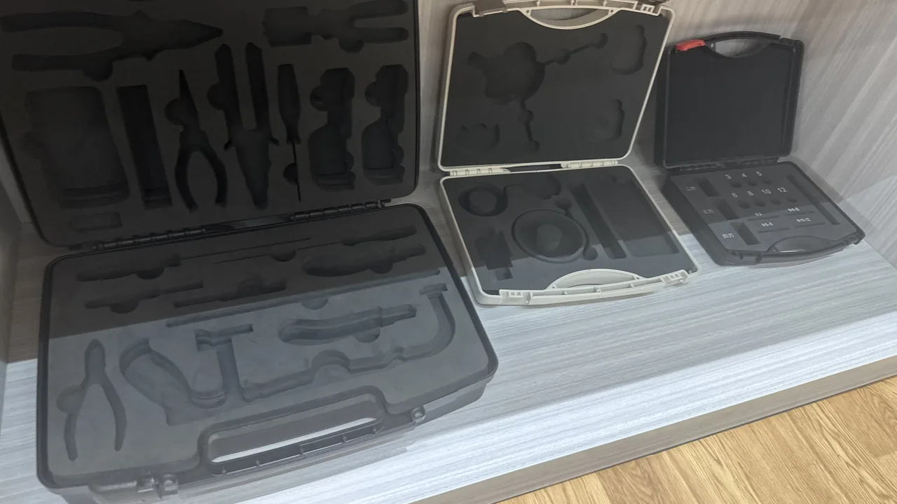
Commissioning and retrofit of an HVAC system often stretches over months. Controllers are pulled from a plant room, loaded onto a van and carried to a rooftop unit. Sensors are issued from stores, trial-fitted in a chilled-water plant room, then sent back for calibration. Across that route, the equipment spends far more time exposed to risk than powered up. Dust, condensation, static discharge, stacking compression and repeated plugging are the real causes of premature control-component failure.
JUNZHIJIA holds a simple principle: the protection level of HVAC control equipment must be set by the environments it will be carried through, not by the final location where it is installed. A controller that works in a temperature-controlled plant room and needs only IP54 on the wall may still be carried onto a cooling tower deck in the rain — and its packaging must be designed for IP66 handling conditions.
Table of Contents
- Mapping Field Risks for HVAC Control Equipment
- How BAS/BMS Controllers Differ from VAV and AHU Controllers in Storage and Transit
- Damper Actuators: Protecting Torque, Shaft Ends and Manual Release Handles
- The Sensor Family and Its Individual Weak Points
- Condensation: Phase-Change Risk from Cold Plant Rooms to Hot Rooftops
- Rooftop and Cooling Tower Environments: Dust, Biofilm and Chemical Water Treatment
- Choosing Between IP54 Indoors and IP66 Outdoors
- Housing Structure, Gaskets and Pressure Equalization Valves
- Cushion Liners and Compartments: Combining EPE, EVA and IXPE
- ESD and Wiring Terminal Protection
- Calibration Certificates and Serial Number Traceability
- Transport and Stacking Tests
- Protection Level Comparison by Installation Location
- Frequently Asked Questions FAQ
- Conclusion and Related Reading
Mapping Field Risks for HVAC Control Equipment
HVAC control devices share a common profile: small in volume, high in unit cost, fragile at the interfaces, and commissioned while live on site. A differential pressure sensor may be palm-sized yet must hold roughly one percent accuracy across a 0 to 2500 Pa range, and a VAV controller with a handful of inputs governs the airflow stability of an entire zone. Their failures are rarely dramatic drops; they are the slow accumulation of hidden damage.
The dominant hidden damage paths on site can be summarized as follows.
| Damage path | Trigger on site | Typical outcome | Packaging countermeasure |
|---|---|---|---|
| --- | --- | --- | --- |
| Electrostatic discharge | Plastic box friction in dry season, synthetic gloves on boards | Blown input-stage op-amp, communication chip latch-up | Conductive liner, grounding wrist strap point, humidity indicator card |
| Condensation uptake | Cold plant room then warm humid rooftop | Surface water on PCB, oxidized terminals | Pressure equalization valve, desiccant, temperature transition procedure |
| Terminal mechanical damage | Repeated plugging, cable tugging | Cracked terminal block, bent pins | Terminal guards, compartmental location, cable retention slots |
| Dust and biofilm | Long open-lid commissioning near rooftops and towers | Blocked vents, drifting optical sensors | Breathable waterproof vent membrane, ventilated sealed chamber |
| Stacking compression | Shared crate with tools and duct sections | Cracked display window, warped shell | Compression ribs, load-bearing compartment base |
| Calibration drift | Transport vibration, thermal and humidity cycling | Zero shift, span shift | Cushion liner, post-transit re-verification |
HVAC control equipment must therefore be protected path by path, not with a single IP number: the countermeasures for static, condensation and terminal damage barely overlap.
How BAS/BMS Controllers Differ from VAV and AHU Controllers in Storage and Transit
BAS/BMS level controllers are normally installed inside plant room control cabinets. They are larger, densely wired and almost never returned to the factory. VAV and AHU controllers are the opposite: they are distributed through ceiling voids, fan coil enclosures and rooftop units, numerous, dispersed and frequently swapped. The storage and transit strategies for the two families therefore diverge sharply.
BAS/BMS controllers are mainly moved as complete cabinets. The focus is on cabinet door latches, glazed viewing windows and internal module retention. If a door springs open in transit, modules slide along their rails and connectors work loose. The fix is internal retaining brackets with cushion pads, transport-specific latches on the doors, and clear marking of center of gravity, orientation and maximum stack height.
VAV and AHU controllers are replenished unit by unit and replaced on site. A single batch is large, the models repeat, and individual units are light, usually 0.3 to 1.2 kg. That profile suits compartmentalized tote cases. Each compartment holds one controller with 5 to 8 mm of clearance so that terminals are never scraped during removal.
| Comparison point | BAS/BMS controller | VAV / AHU controller |
|---|---|---|
| --- | --- | --- |
| Typical location | Plant room cabinet, telecom room | Ceiling void, unit interior, rooftop |
| Removal frequency | Low, moved as a cabinet | High, replaced individually |
| Dominant risk | Door springing, module sliding | Terminal scraping, batch mixing |
| Recommended case | Cabinet transport frame plus rain hood | Compartment tote plus locating liner |
| Sealing need | Rain protection during transit (IP54 class) | Dust and moisture protection in temporary store (IP65 class) |
| Labeling focus | Center of gravity, orientation, stack limit | Model, address code, floor zone |
VAV controllers are usually address-coded before dispatch, so a mixed batch forces every unit to be rescanned on site. The number of compartments should map one-to-one onto floors or zones, with a cross-reference table printed inside the lid.
Damper Actuators: Protecting Torque, Shaft Ends and Manual Release Handles
Damper actuators are the least electronics-like members of the family, containing a motor, reduction gear, output shaft, coupling and manual release handle. Their weak points cluster in three places.
The first is the output shaft and coupling. An actuator connects to the damper shaft through a square or round shaft, so any axial force transmitted back through the shaft reaches the gearbox directly. In bare shipment, a pressed shaft end produces abnormal gear backlash, which shows up as continued micro-movement after the actuator reaches its end position. Packaging must reserve at least 15 mm of axial clearance at the shaft end, or suspend the shaft in a grooved locating block.
The second is the manual release handle. Most actuators carry a push-down or lever mechanism for manual damper adjustment during a power outage. It protrudes and is the easiest feature to snag on other contents. The locating liner should hold the handle in its natural released position, never forced into the working position.
The third is the housing finish and calibration label. Actuator housings are usually die-cast aluminum with paint or anodizing, and neither is hard. Mixed with copper busbars and other metal parts, the finish chips easily. These devices should be segregated from power-side hardware, following the cabinet logic described for the power distribution cabinet case, so that precision low-voltage items and heavy power items are physically separated inside the box.
| Actuator area | Typical damage | Packaging requirement |
|---|---|---|
| --- | --- | --- |
| Output shaft / coupling | Axial pressing increases gear backlash | Shaft suspended, at least 15 mm axial clearance |
| Manual release handle | Snagging, forced into working position | Locating block leaves room for released position |
| Die-cast housing | Chipped paint, scratched anodizing | Separate compartment, isolated from heavy metal |
| Wiring terminals | Plug damage, lost dust caps | 20 mm of hand clearance above terminals |
| Mounting bracket | Deformation causing concentricity error | Bracket laid flat, never stacked under load |
Mid-size actuators in the 5 to 20 N·m range dominate real projects, and their gear sets are highly sensitive to axial clearance. Post-transit inspection should not stop at "does it run": with power off, measure the manual operating torque and flag deviations above roughly 15 percent. That check catches most gear damage before installation.
The Sensor Family and Its Individual Weak Points
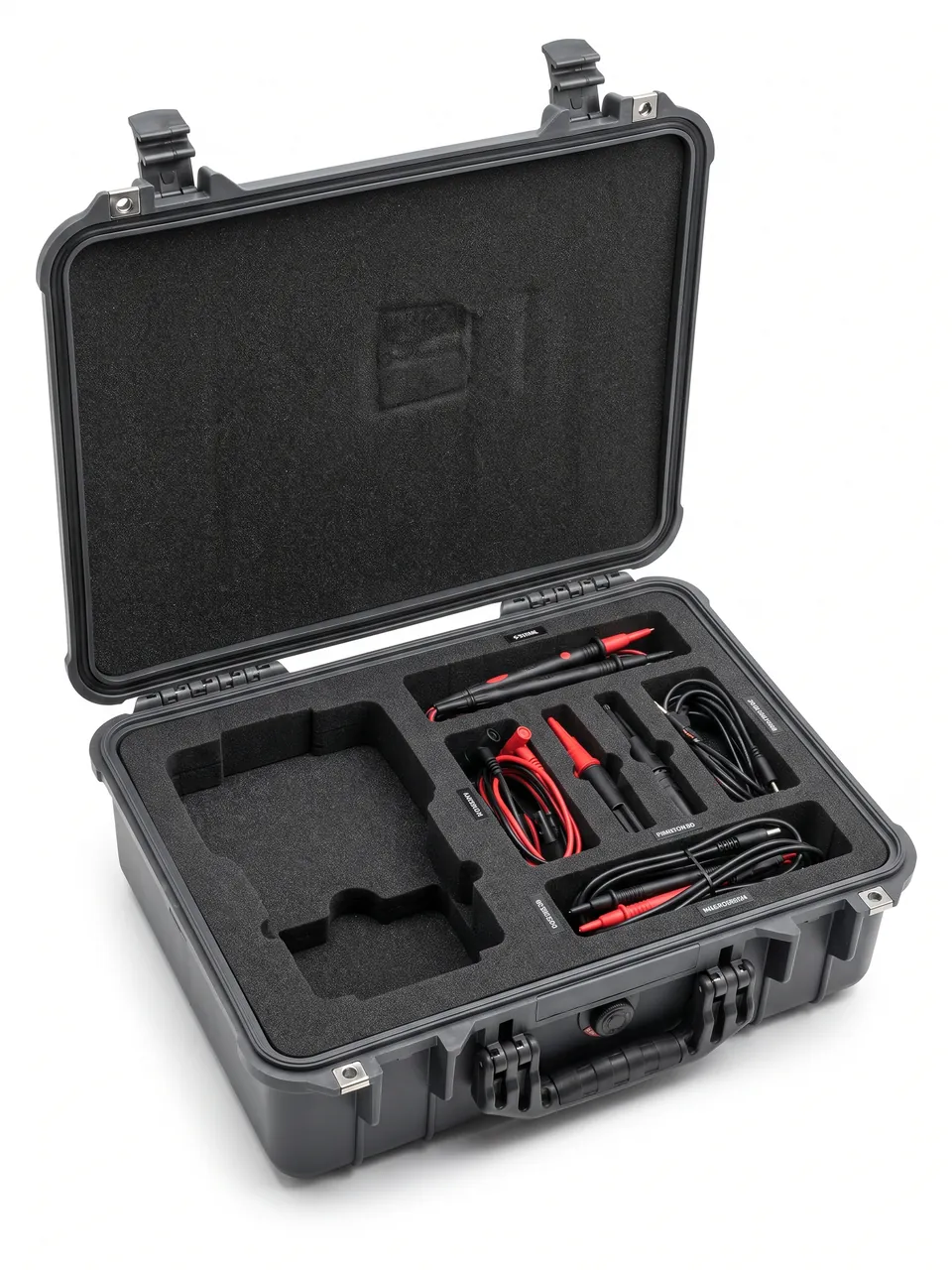
HVAC systems use a wide range of sensors, but the protection logic groups by sensing element form. Temperature and humidity sensors usually expose a thermistor or a capacitive humidity element. Carbon dioxide sensors rely on an infrared optical cavity. Differential pressure sensors use a diaphragm with a micro-pressure transmitter. Flow sensors cover impeller, electromagnetic and ultrasonic principles.
| Sensor type | Sensing element | Main failure driver | Packaging emphasis |
|---|---|---|---|
| --- | --- | --- | --- |
| Temperature (RTD / thermocouple) | Exposed sensing probe | Bent probe, snapped RTD leads | Probe suspended, leads coiled separately |
| Relative humidity | Capacitive polymer humidity layer | Chemical contaminants, prolonged saturation | Sealed chamber plus desiccant, recalibrate after opening |
| Carbon dioxide | NDIR optical cavity and source | Dust blocking the light path, mechanical shock | Dust-proof breathable membrane, protective optical window cap |
| Differential pressure | Silicon diaphragm and pressure ports | Distorted ports, overpressure shock | Reinforced port protection, overpressure limit marked |
| Flow | Impeller, electrodes or transducer | Bearing wear, electrode scaling | Separate compartment, kept away from magnetic parts |
Humidity sensors are the most sensitive to the packaging environment. A capacitive humidity layer keeps absorbing water in a humid atmosphere, and long storage inside a moisture-laden sealed box shifts the response curve as a whole. Humidity sensor packaging should therefore breathe: the outer case seals against rain while a breathable waterproof vent membrane allows slow pressure and humidity exchange, backed by silica gel desiccant and a humidity indicator card, commonly with a 10 to 60 percent color-change window.
NDIR carbon dioxide sensors fear dust instead: once the optical window is contaminated, the calibration curve drifts and readings run consistently low. Dust levels near rooftops are far higher than in plant rooms, so the protective cap should stay in place through handling.
Condensation: Phase-Change Risk from Cold Plant Rooms to Hot Rooftops
HVAC equipment works with hot and cold air, so phase-change risk is inherent to its storage and transit. The classic case is a cold surface entering a warm humid space. A differential pressure sensor held for hours in a 12 °C chilled-water plant room is taken out and carried to a rooftop at 34 °C and 80 percent relative humidity. Water vapor condenses immediately on the cold sensor body and housing. If the case is open at that moment, condensate runs straight into the wiring terminals.
The reverse happens too. In winter, equipment stored in an outdoor warehouse at -10 °C is moved into a plant room at 22 °C. The 32 °C span again produces condensation, and because the equipment is the cold side, the condensation often forms on interior surfaces.
| Scenario | Temperature span | Condensation site | Countermeasure |
|---|---|---|---|
| --- | --- | --- | --- |
| Cold plant room to warm wet rooftop | About 20 to 25 °C | Housing and terminal surfaces | Keep case closed, allow 30 minutes to equilibrate |
| Outdoor cold store to indoor plant room | About 25 to 35 °C | Inner case wall and device surfaces | Desiccant plus a settling period before opening |
| Rooftop sun exposure to night cooling | About 15 to 20 °C | Water vapor in the internal air | Pressure equalization valve to vent pressure and moisture |
| Rainy-day open commissioning | Instantaneous | Wiring terminals and PCB | Work under a rain hood, terminals facing down |
The most practical engineering answer is not to chase absolute freedom from condensation, but to control when the case is opened. A workable rule reads: after arrival, let the equipment settle closed for at least 30 minutes until its housing approaches room temperature. Combined with a pressure equalization valve on the housing, this prevents the "breathing" pump-in of moist air driven by pressure differential.
Rooftop and Cooling Tower Environments: Dust, Biofilm and Chemical Water Treatment
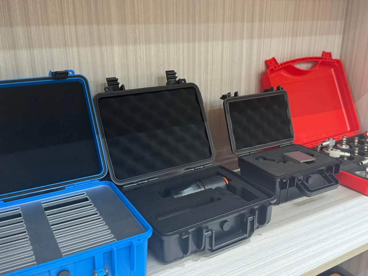
Rooftop units and cooling tower decks are the harshest HVAC sites, and the risk is layered rather than singular.
The first layer is dust. Rooftop deposits are mostly atmospheric fallout and nearby construction dust with a wide particle range. These particles enter actuator vents, sensor optical windows and terminal gaps, then form conductive or corrosive paths once they absorb moisture.
The second layer is biofilm. Cooling tower drift creates a persistent damp film on nearby surfaces that supports algae and biofilm. Biofilm itself does not conduct, but its metabolic by-products are weakly acidic and slowly corrode platings and terminals. A control box left open during commissioning often shows mold on the inner wall before any electronics fail.
The third layer is chemical water treatment. Cooling water systems routinely dose corrosion inhibitors, scale inhibitors, biocides and pH adjusters. Drift carries these chemicals onto equipment surfaces, where they dry into salt residues. Those residues are strongly hygroscopic and re-form an electrolyte film as night humidity rises. To set verification conditions for this corrosion path, refer to the salt spray corrosion test judgment methods.
| Risk layer | Source | Effect on equipment | Case countermeasure |
|---|---|---|---|
| --- | --- | --- | --- |
| Dust | Atmospheric fallout, construction dust | Blocked vents, contaminated light path | Breathable waterproof vent membrane, slight positive ventilation |
| Biofilm | Cooling tower drift | Acidic metabolites corroding platings | Shorter open-lid time, optional antimicrobial inner wall |
| Chemical residue | Water treatment chemicals | Hygroscopic, terminals rust | Sealed chamber plus wipe-down on arrival |
| Ultraviolet | Summer sunlight | Plastic aging, faded labels | UV-resistant housing material, see UV aging practice |
| Thermal cycling | Day and night alternation | Breathing effect draws in moisture | Pressure equalization valve plus desiccant |
A practical rooftop habit is to schedule open-lid work into dry periods and keep a sealable bag inside the case for the removed dust caps and terminal guards, which are otherwise expensive to replace.
Choosing Between IP54 Indoors and IP66 Outdoors
Many procurement arguments come down to whether to specify IP54 or IP66. The answer depends on exposure across the lifecycle, not on the installation location.
The first digit of an IP code covers solids and the second covers water. IP54 means dust protection level 5, where dust ingress is not fully prevented but is insufficient to affect operation, combined with water protection level 4, resistance to splashing from any direction. IP66 means dust-tight plus resistance to powerful water jets. The gap is not only numeric; the sealing architecture moves from a simple lip to a fully compressed perimeter gasket.
| Operating scenario | Dust intensity | Water exposure | Recommended class |
|---|---|---|---|
| --- | --- | --- | --- |
| Fixed installation in a temperature-controlled plant room | Low | None | IP54 is sufficient |
| Plant room with floor washdown | Low | Splash | IP65 |
| Long-term storage in a ceiling void | Medium | None | IP54 to IP65 |
| Beside a rooftop unit | High | Rain | IP66 |
| Cooling tower deck | High plus chemical | Rain plus drift | IP66 with chemical-resistant housing |
| Long-term open-air outdoor storage | High | Rain and standing water | IP66 to IP67 |
Set the class by the worst handling node, verify it against the longest storage period, and work backward from the least convenient maintenance posture. The third is most often ignored: if a controller must be opened one-handed inside a narrow ceiling void, lid angle, latch count and opening force must all suit that posture, or crews will leave the lid half open and the rating becomes meaningless.
Housing Structure, Gaskets and Pressure Equalization Valves
The structure of an HVAC control case resolves three conflicts. Better sealing means a larger pressure differential. More stable stacking means harder removal. Lower weight means weaker compression resistance.
Wall thickness and reinforcing ribs. Injection-molded cases typically use 3 to 5 mm walls with external ribs that form an I-beam-like section. Because rooftop storage risks softening under summer sun, the heat deflection temperature should exceed the site extreme by at least 20 °C. Cutouts for cable or mounting holes should avoid rib nodes, since cutting at a node reduces local stiffness.
Gasket profile. HVAC cases mostly use silicone or EPDM gaskets. Silicone handles roughly -50 °C to +200 °C with good resilience, which suits transport with large temperature swings, while EPDM offers better weathering and lower vapor permeation at lower cost. The gasket is laid as a seamless loop and seals through lid compression, typically held between 20 and 30 percent. Too little leaks; too much accelerates aging.
Pressure equalization valve. This is the highest-value small component in an HVAC scenario. When a case travels from a cold zone to a warm one, or heats up in sunlight, the differential across the wall can reach several kPa. Without a valve, it keeps squeezing the gasket and, at the moment of opening, pulls humid air inward. The valve equalizes through a micro-orifice while a hydrophobic membrane blocks liquid water, and it is the direct countermeasure to the breathing-driven moisture uptake described earlier.
| Component | Key parameter | Common failure | Design point |
|---|---|---|---|
| --- | --- | --- | --- |
| Housing | 3 to 5 mm wall, rib section | Softening in sun, local warping | Keep cutouts away from rib nodes |
| Gasket | 20 to 30 percent compression | Hardening, permanent set | Seamless loop, silicone or EPDM |
| Pressure equalization valve | Cracking differential, airflow | Clogged hydrophobic membrane | Periodic inspection, keep grease away |
| Latch | Opening force, cycle life | Sticking, fracture | Matched to gasket compression |
| Hinge | Opening angle, axial play | Sag that prevents a tight lid | Metal pin plus travel stop |
One point deserves emphasis: sealing and stacking must be verified together. Under stack load the side wall deflects slightly, and if that wall is the gasket sealing face the deflection changes compression. Stacking tests should therefore include a seal check under load, not only an empty-case test.
Cushion Liners and Compartments: Combining EPE, EVA and IXPE
Cushion design for HVAC control equipment has a special constraint. Its mass distribution is highly uneven. An actuator is heavy at one end, a sensor is a slender rod, and a controller is a flat block. Three shapes in one case need three cushioning strategies.
| Foam type | Density and feel | Cushioning behavior | Best for |
|---|---|---|---|
| --- | --- | --- | --- |
| EPE (expanded polyethylene) | Low density, soft | Good compression recovery under repeated impact | Large housings, whole-unit cushion layers |
| EVA | Medium to high density, firm | Dimensionally stable, precision cuttable | Compartment skeleton, sensor locating slots |
| IXPE | Cross-linked polyethylene, medium density | High closed-cell ratio, good moisture barrier | Around wiring terminals, moisture barrier layer |
| PU sponge | Low density, pliable | Conforms to irregular surfaces | Surface anti-scuff lining |
| Rigid PE foam | High density, stiff | Strong load bearing, resists compression | Base load layer, stacking support blocks |
The common working combination is EVA for the skeleton, EPE for cushioning and IXPE for the moisture barrier. EVA is CNC-cut to trap each unit's outline, EPE fills the gaps and absorbs impact energy, and IXPE sits against the equipment as a barrier against moisture and scuffing. This three-layer build often outperforms a single high-density foam in drop testing, because it splits locating and energy absorption between materials. For a deeper comparison, see case internal foam types.
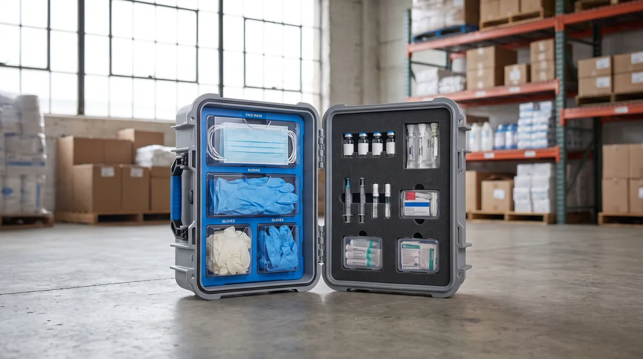
Compartment design must also allow hand clearance. If adjacent compartments touch, a gloved finger cannot enter, so a 10 to 15 mm notch or rounded chamfer on each compartment wall makes gripping possible. This matters most in winter outdoor work, when thicker gloves turn poor clearance into pulling on the terminals.
ESD and Wiring Terminal Protection
Electrostatic discharge is the most insidious killer of HVAC control equipment. In winter, plant room humidity can fall to 20 percent, and a person walking on synthetic carpet can accumulate several kilovolts. That discharge is enough to puncture the gate oxide of an input-stage op-amp, and the result is often not immediate failure but intermittent communication faults weeks later.
The protection system has three layers.
The first is a conductive environment inside the case. A conductive liner may be fitted, or a conductive layer laminated onto the foam surface so that charge has a drain path instead of accumulating. For totes handled frequently, a grounding point can be added so the case is bonded to a grounding bar before opening.
The second is handling procedure. Operators wear anti-static wrist straps or gloves and touch a metal part of the case to bleed charge before contacting a board. The rule belongs in the site work instruction, not only in training.
The third is terminal protection. Wiring terminals are another high-frequency failure point.
| Terminal risk | Cause | Protection |
|---|---|---|
| --- | --- | --- |
| Plug damage | Repeated plugging, angled force | Terminal guard plus straight-insert guide slot |
| Bent pins | In-case compression, foreign objects | Clearance above terminals, dust caps |
| Oxidative corrosion | Moisture, hand sweat, chemical residue | Terminal protective grease, desiccant |
| Mis-wiring | Many same-color cables co-stored | Cable identification, separate cable channels |
| Lost labeling | Labels peeling off | Laser marking plus silkscreen dual identification |
The core principle of terminal protection is that when the equipment is unpowered, the terminals must be physically isolated. The common practice is to ship terminal guards or dust plugs with the case and print a pre-handling checklist inside the lid. The checklist looks trivial, yet it measurably reduces site returns caused by poor plugging practice.
Calibration Certificates and Serial Number Traceability
Commissioning and acceptance of HVAC control equipment depend heavily on calibration data. Sensors are usually calibrated before dispatch with a certificate recording the serial number, calibration date, calibration points and uncertainty. If the case cannot keep equipment, certificate and serial number travelling together, the site ends up waiting because the device arrived without its paperwork.
Traceability design involves three actions.
First, make the serial number visible. The device serial number often sits on the base or the side, invisible once packed. The corresponding compartment should be printed or labeled with the same serial number so it is visible when the lid opens.
Second, give certificates a dedicated pocket. A separate document compartment keeps paper away from the equipment, preventing foam from curling the sheets and moisture from reaching them. The pocket should be moisture-protected, because calibration paper wicks water and the printing smears.
Third, build a scannable asset record. Binding case number, device serial number and calibration expiry into a QR code lets a technician scan and see the next calibration date, which pays off where equipment counts are high; see case asset QR code tracking.
| Traceability element | Carrier | Common problem | Countermeasure |
|---|---|---|---|
| --- | --- | --- | --- |
| Device serial number | Nameplate on the unit | Invisible once packed | Duplicate marking at the compartment |
| Calibration certificate | Paper document | Moisture curling | Separate moisture-proof document pocket |
| Calibration expiry | Database | Not queryable on site | QR code linked to expiry date |
| Packing list | Accompanying sheet | Does not match contents | Weigh and verify before closing |
| Repair record | Service form | Lost, repeated repairs | Archived against the serial number |
Certificate validity depends not only on time but also on environmental exposure in transit, so equipment that has seen severe vibration should have zero and span re-verified even before expiry.
Transport and Stacking Tests
Verification of an HVAC control case is about reproducing rough handling in the laboratory. Common methods include controlled drop, random vibration, compression stacking and thermal cycling.
| Test | Reference method | HVAC relevance |
|---|---|---|
| --- | --- | --- |
| Drop test | Controlled drop graded by weight | Rooftop hoisting, dropped during manual handling |
| Random vibration | Transport vibration spectrum | Long road haulage, last-mile delivery |
| Stacking compression | Constant load hold | Multi-tier warehouse storage, truck stacking |
| Thermal and humidity cycling | Alternating high and low temperature | Temperature span from plant room to rooftop |
| Seal check | Leakage and pressure decay | Gasket and equalization valve effectiveness |
| Salt spray | Neutral salt spray exposure | Cooling tower drift and chemical residue |
Thermal and humidity cycling is the one test that cannot be skipped in an HVAC scenario. It verifies gasket compression recovery and whether the pressure equalization valve draws air inward during cooling. A common defect is a hydrophobic membrane with too little area, which cannot equalize during a fast cooldown and leaves negative pressure that pulls moisture through weak gasket points. A drop from 40 °C at 85 percent relative humidity to 5 °C at 30 percent relative humidity, held for four hours, reproduces this well; judgment points appear in high-low temperature test cases.
Stacking tests should record deflection under load and residual deformation afterwards: deflection above one third of gasket compression risks seal failure, and residual deformation above 2 mm makes repeated stacking unsuitable.
Protection Level Comparison by Installation Location
The table below consolidates the analysis into a selection reference for engineering and procurement.
| Installation location | Environment | Recommended equipment class | Recommended packaging class | Storage and transit requirement |
|---|---|---|---|---|
| --- | --- | --- | --- | --- |
| Plant room control cabinet | Constant temperature, low dust | IP54 | IP54, rain protection | Indoor rack, moisture-proof pallet |
| Telecom room or ceiling void | Temperature swings, dust | IP54 | IP65, compartment tote | Horizontal stacking, no more than 3 tiers |
| Inside an air handling unit | Vibration, airflow | IP55 | IP65, anti-vibration liner | Avoid mixing with heavy metal parts |
| Beside a rooftop unit | Rain, UV, dust | IP66 | IP66, UV-resistant housing | Under shade, at least 100 mm off the deck |
| Cooling tower deck | Drift, chemical, biofilm | IP66 | IP66 plus chemical-resistant housing | Short-term storage, 7 days or less |
| Open-air outdoor storage | Rain, standing water, span | IP66 to IP67 | IP67 with equalization valve | Off floor and wall, protected from pooling |
| Long-distance transport | Vibration, stacking, thermal span | Set by highest exposure | Equalization valve and desiccant | Re-verify seal and calibration after transit |
Equipment protection class and packaging protection class are two independent specifications. A controller that ultimately needs only IP54 can ship in an IP66 tote because the tote faces harsher handling, and an IP66 rooftop device in an IP54 package has already taken on water before it reaches the roof.
Frequently Asked Questions FAQ
Q: Why not simply reuse the equipment's own IP rating for the HVAC control case?
A: An equipment IP rating describes protection in its installed state, assuming the unit is fixed, wired and its sealing faces are compressed. During storage and transit the unit is unmounted, unwired and may have covers open, so the exposure is completely different. Carried past a rooftop or a cooling tower deck, dust and drift intensity far exceeds that at the installed position, and the equipment may sit in that condition for weeks rather than a few operating hours. Reusing the equipment rating for the packaging produces a mismatch where a nominally IP65 device ships in a splash-resistant box and arrives already wet. Thermal cycling adds a second problem, because a case holding air from a cold plant room will condense internally as it warms up. The correct approach is to set the packaging class by the harshest node in the whole lifecycle, usually one level above the installation requirement, and to mark stacking limits and orientation clearly on the case.
Q: Moving controllers from a plant room to a rooftop in the rainy season, which hidden damage is most likely?
A: The most likely is terminal corrosion and surface leakage on the PCB caused by condensation. After a long stay in a cool plant room, the housing temperature approaches room temperature, and on entering a hot humid rooftop environment water vapor condenses rapidly on cold surfaces. If the lid is open at that moment, condensate runs along the wiring terminals, oxidizing them and raising contact resistance, which shows up as analog signal drift or intermittent communication faults. Damage of this kind is rarely obvious at first power-up and may appear only weeks later, which makes it expensive to trace back to handling. A related failure is dust bonding to damp terminals and bridging adjacent poles. The countermeasure is to keep the case closed during the move, let it settle indoors for at least 30 minutes before opening, and equip it with a pressure equalization valve, a desiccant pack and a humidity indicator card so the exposure history can be read afterwards.
Q: How should the compartment count of a VAV controller tote be determined?
A: The compartment count should follow the issuing and zoning logic on site rather than the case dimensions alone. A common approach is to make the count an integer multiple of controllers per floor or per air-conditioning zone, so a zone needing 12 units uses a 12-compartment case and one case maps to one zone. The value is mistake-proofing: controllers are usually address-coded and airflow-calibrated before dispatch, and mixing units with different address codes forces every unit to be rescanned, adding labor and risking a wrong address being written on site. Each compartment should also allow 5 to 8 mm of clearance with a finger notch, so that a gloved hand can lift the controller cleanly instead of pulling on the terminals. A cross-reference table between compartments and address codes should be fixed inside the lid so the batch can be checked immediately on opening, and the exterior should carry the zone number. Where controllers of several models share one case, a coloured divider per model prevents mixing without adding a second tote.
Q: What do dust and drift near rooftops and cooling towers do to the outside of a control case?
A: The effects come in two layers. Physically, atmospheric fallout and construction dust clog vents and contaminate sensor optical windows; once the light path of a carbon dioxide sensor is obscured, readings run systematically low and the error is easily mistaken for a control fault. Chemically, cooling tower drift carries corrosion and scale inhibitors, biocides and other treatment chemicals, which dry into hygroscopic salt residues. As night humidity rises, those residues re-form an electrolyte film that slowly corrodes platings and terminals, and over the long term the damp film supports weakly acidic biofilm that damages labels and painted surfaces. Rooftop cases should therefore use chemical-resistant, UV-stable housing material, with EPDM preferred for the gasket because of its weathering and moisture-vapor performance. Open-lid commissioning should be scheduled into dry periods to shorten the exposure window, and the exterior should be wiped down on arrival. Where a site runs several towers, the chemical load varies with the dosing regime, so the case specification should be checked against the actual treatment programme rather than a generic outdoor rating.
Q: What role does a pressure equalization valve play in transporting HVAC control equipment?
A: It lets the internal and external pressures equalize slowly while blocking liquid water. Without a valve, a case that experiences day and night temperature swings, or travels from a cold zone into a hot one, can see several kPa of differential. That differential keeps squeezing the gasket, holding it under abnormal compression and accelerating aging, and at the moment of opening it creates negative pressure that pulls humid outside air inward. The valve exchanges gas through a hydrophobic breathable membrane, relieving pressure without letting droplets pass through. When selecting a valve, review the cracking differential, the airflow rate and the membrane area, because too small an area cannot keep up during rapid cooling and allows inward suction instead of relief. Mount the valve away from the base of the case where water might pool, and check the membrane periodically, since grease or dust contamination will blind it. A valve is not a substitute for a sound gasket, because it equalizes pressure but cannot compensate for a torn seal or a lid left unlatched.
Q: How do packaging needs differ fundamentally among temperature, humidity and carbon dioxide sensors?
A: They differ because the sensing mechanisms differ. A temperature sensor's probe is a mechanically fragile part and the RTD leads are thin, so the main risks are bending and breakage; the packaging emphasis is suspending the probe in a molded pocket and coiling the leads separately so they cannot be strained. A humidity sensor's capacitive layer continuously exchanges moisture with its surroundings, and long storage in a humid sealed case shifts the response curve as a whole, so its packaging should breathe, using a vent membrane with silica gel desiccant and a humidity indicator card, followed by recalibration after opening. A carbon dioxide sensor uses an infrared optical cavity and most fears dust contaminating the light path, so the optical window needs a protective cap that stays in place through handling and comes off only before power-up. Flow sensors add a fourth case, because impellers and electrodes are damaged by impact and scaling rather than by moisture alone. One liner design cannot serve all four.
Q: When cases are stacked in transit, what failure is most often overlooked?
A: The most overlooked is seal failure under load. An empty-case seal test shows normal gasket compression, but when the case carries a stack load the side wall deflects slightly. If the gasket sealing face sits mid-wall, that deflection directly changes the actual compression, leaking where compression is low and speeding permanent set where it is high. This failure is invisible in static testing yet appears after long-haul transport, usually as a few damp units at the bottom of a pallet. Stacking tests should therefore include a seal check under load and record deflection together with residual deformation after the load is removed. A practical criterion is deflection no greater than one third of gasket compression and residual deformation no greater than 2 mm. Cases that will be stacked more than three tiers high in a warehouse should also carry a printed load limit, so nobody exceeds the tested condition on site, and recording the pallet position of each unit helps because bottom-tier cases carry the greatest load.
Q: How can calibration certificates shipped with the case be kept valid and trustworthy?
A: The key is a complete chain linking equipment, certificate, serial number and transport events. Device serial numbers are normally invisible once packed, so the matching compartment should carry the same number for immediate confirmation when the lid opens. Calibration certificates need a dedicated moisture-proof document pocket, separated from the equipment so foam cannot curl the sheets and moisture cannot reach the paper. More importantly, certificate validity does not equal trustworthy data: equipment that has seen severe vibration or thermal cycling should have zero and span re-verified even before expiry, because diaphragms and optical elements may already have shifted. Binding case number, serial number and calibration expiry into a QR code gives technicians a status check on the spot, and logging transport events closes the loop whenever a route involves large temperature swings.
Conclusion and Related Reading
Set the protection class by the worst handling node, control every opening, and trace each unit. JUNZHIJIA supplies custom liners, tooling and OEM/ODM service for HVAC control cases.
Related Reading