

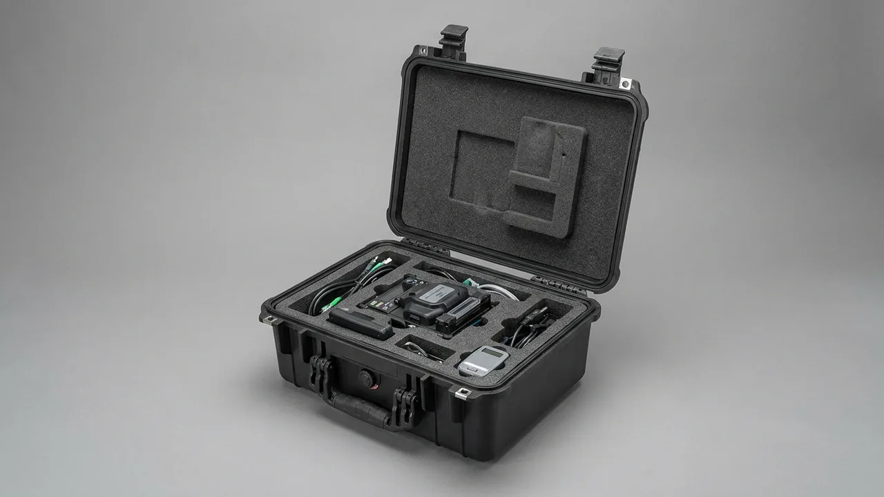
The most expensive and hardest-to-replace parts of an ice machine are the ones that touch water and ice directly. The evaporator drum is both the heat transfer surface and the surface on which the ice layer grows. A scraper blade rotates against that drum with a clearance of a fraction of a millimetre. A pump sprays water evenly across the drum wall, and food-grade piping moves water and refrigerant in and out. The first specification for an ice machine component case is therefore not impact resistance but simultaneous protection of three things: drum roundness, blade edge geometry, and the internal cleanliness of every pipe. A case that only survives a drop test can still deliver dented drums, curled blade edges and mouldy tubing. This guide is written for ice machine manufacturers, after-sales and spare parts departments, food plant maintenance managers, and exporters of food machinery. It breaks the problem into eight verifiable dimensions: hygiene compliance, drum protection, blade restraint, water circuit cleaning, moisture and mould control, passivated surface care, case and insert selection, and packaging validation.
The usual shipping practice is to put the disassembled drum back into its original carton, fill the gaps with bubble wrap, slide the scraper blade inside the drum or drop it into the same wooden crate as the pump and fittings, and leave every pipe end open with a couple of wraps of tape. That packing stops a visible knock but does nothing about three specific failure modes. First, drum wall scratches and local indentations; once roundness changes, ice thickness becomes inconsistent and ice release becomes harder. Second, blade edge curling and carrier distortion; a scraper blade is a thin formed part, and concentrated pressure at any point can cause damage that cannot be repaired on site. Third, internal contamination and residual-water mould growth; an open pipe inside a hot, humid sea container both collects dust and grows biofilm, and that biofilm reaches the next batch of ice. Ice machine cases should be specified from the disassembly list, not from the price of the shell.
Contents
- 1. How ice machine components stack transport constraints on operating conditions
- 2. Component inventory and the weak point of each item
- 3. Food-grade hygiene: packaging design under GB 14881 and GMP
- 4. Evaporator and ice drum: roundness and passivated surface protection
- 5. Scraper blade and blade carrier: the no-pressure, no-stacking rules
- 6. Pump and spray system: separating impeller, shaft seal and motor
- 7. Food-grade piping: cleaning, drying and capping every port
- 8. Moisture and mould control: keeping internal humidity below the threshold
- 9. Passivated stainless surfaces and the chloride risk
- 10. Insert structure and zoning: removable modules, restraint and drainage
- 11. Case selection: IP rating, latches, hinges and pressure equalization
- 12. Packaging validation: GB/T 4857, ISTA and salt spray planning
- 13. Purchasing acceptance checklist and common misconceptions
- Frequently Asked Questions
- Conclusion and Further Reading
1. How ice machine components stack transport constraints on operating conditions
Ice machines are grouped by the form of ice they produce: cube, tube, flake, scale and nugget machines. Cube and tube machines are mould-release designs, where the evaporator is a set of individual moulds or tubes released with hot gas. Flake and scale machines are rotary designs, where the evaporator is a grooved drum and a spiral scraper or blade carrier continuously shaves the ice layer off the wall. The two families are sensitive to completely different things in transit: mould-release machines to seal faces and hot-gas water circuits, rotary machines to drum roundness and blade clearance.
Placing operating conditions next to transport conditions makes the conflict obvious:
- Operating side. The drum wall sits between roughly -5 C and -25 C for its whole service life. Ice forms, thickens and releases repeatedly, so the metal surface alternates between low-temperature embrittlement risk and mechanical abrasion as the ice layer shears away.
- Transport side. Inside an export sea container the air temperature can exceed +55 C with relative humidity above 85 percent for long periods, and day-night swings cause repeated condensation. A route through high latitudes can cross a 60 C span end to end. The same case therefore experiences everything from frost to a humid greenhouse.
- Hygiene side. The drum outer wall, moulds, blades, spray pipes and fittings are food contact surfaces or near-contact surfaces. GB 14881 requires food production equipment surfaces to be smooth, cleanable and corrosion resistant, and food contact metals must also satisfy the GB 4806 series requirements for stainless steel.
- Accuracy side. Drum roundness sets ice thickness consistency, and the single-side clearance between blade and wall is typically only 0.1 to 0.5 mm. One local indentation in the wall or one curled blade edge produces uneven ice thickness, difficult release and higher energy consumption per tonne of ice.
The intersection of these four constraints is why an ice machine component case cannot reuse the logic of a general industrial spare parts box. A general box prioritises impact resistance and handling convenience. An ice machine case must add three requirements on top: food-grade cleanability, moisture-tight storage, and zero compressive load on the blade edge. Miss any one of them and the problem surfaces during commissioning as low output or soft ice, when the cost of rework is far higher than the cost of the packaging.
2. Component inventory and the weak point of each item
A medium-capacity flake ice machine yields a dozen or more items that need to travel, and their materials, stiffness and failure modes differ widely. Classifying them first is what makes zoning decisions defensible rather than accidental.
| Component | Typical material | Primary weak point | Protection focus |
|---|---|---|---|
| --- | --- | --- | --- |
| Ice drum / evaporator | Stainless 304 / 316L, nickel-plated carbon steel | Wall roundness, groove edges, circumferential welds | Full-perimeter flexible support, no hard point support |
| Ice moulds / tube bank | Stainless steel, nickel-plated copper | Mould mouth seal faces, hot gas circuit | Separate cavities, mouths facing up |
| Spiral scraper blade | Formed stainless, engineered plastic edge | Edge straightness, back face flatness | Dedicated blade seat, edge left unsupported |
| Blade carrier / main shaft | Stainless steel, alloy steel | Journal fit faces, keyways | Vertical attitude, protective sleeves on journals |
| Spray water pump | Cast iron housing, stainless shaft | Impeller, mechanical seal, terminal box | Drained and blown dry, terminal box up |
| Spray pipe / water tray | PVC, stainless steel, PP | Nozzle deformation, tray flatness | Flat, single layer, nozzle face up |
| Food-grade hose and pipe | Silicone, EPDM, food-grade PVC | Internal biofilm, port deformation | Dry then cap both ends, coil without kinks |
| Water and solenoid valves | Brass, stainless, engineering plastic | Spool, coil leads, diaphragm | Compartmented, coil separately protected |
| Drive motor / gearbox | Aluminium or cast iron housing | Output shaft, oil seal, fan cowl | Upright, shaft end protected |
| Seals and O-rings | Food-grade silicone, EPDM, FKM | Compression set, ozone cracking | No load, dark, separate small pockets |
| Controls and sensors | Boards, probes, harness | Static, moisture, bent pins | Anti-static bag plus desiccant |
Two items in that table are routinely mishandled at the packing bench. The first is the scraper blade, which must not share a cavity with the drum. Even with bubble wrap between them, the drum's own weight keeps bearing on the blade edge through every vibration cycle of a long journey, producing micro indentations that are invisible at outgoing inspection but leave a strip of ice unscraped once the machine runs. The second is food-grade hose, which must be completely dry before it is capped. A cap keeps dust out but cannot stop residual water inside from growing biofilm in a sealed warm environment, where the enclosed humidity actually accelerates deterioration.
3. Food-grade hygiene: packaging design under GB 14881 and GMP
When a component will end up in contact with drinking water and edible ice, the packaging material itself enters the scope of food safety assessment. The core demand of GB 14881 is that equipment and utensils have smooth, cleanable, corrosion-resistant surfaces that cannot contaminate food. A GMP environment adds cleaning validation and cross-contamination control. Translated into packaging language, those requirements become four design rules.
First, no fibrous materials inside the case. Corrugated board, wood shavings, moulded pulp and cotton cloth are all particle sources and moisture sinks; in a hot, humid sea container they absorb water and become a mould substrate. Use closed-cell foam or food-grade engineering plastic parts instead: no water absorption, no shedding.
Second, surfaces that touch components must tolerate wipe-down disinfection. Specify an insert module that can be lifted out whole, wiped with 70 percent ethanol, isopropyl alcohol or a peracetic acid based sanitiser, air dried and refitted. Where the insert is built from segments, cover the seams with a continuous sheet so no gap can trap water.
Third, no chlorine-bearing or sulphur-bearing auxiliary materials. Polysulphide sealants, chlorinated foams and some low-cost rubber pads release corrosive vapours in a closed volume, which attacks both stainless steel surfaces and copper parts.
Fourth, document the packing environment and the opening environment. For customers with a formal cleaning validation requirement, include a packing list and a cleaning record card in the case stating the cleaning method, the person who confirmed dryness, the packing date and the desiccant indicator number. This is not paperwork for its own sake; it is the only evidence available if a quality dispute arises.
Choosing packaging materials does not change the food-grade status of the components themselves. Whether a drum or blade is compliant depends on its material and surface treatment under the GB 4806 series and the machine certification. The job of the case is to deliver surfaces that were compliant at the factory in the same condition at the point of use. Comparable clean-room practice is described in aseptic filling equipment cases and dairy processing parts transport protection.
4. Evaporator and ice drum: roundness and passivated surface protection
The drum is the largest and heaviest single item in the case, and the one that tolerates local deformation least. After machining and polishing it carries ice release grooves on its outer or inner wall and welded heads with refrigerant connections at both ends. Its stiffness is respectable, but its resistance to local indentation is limited. On a 300 mm diameter stainless drum with a 3 mm wall, a hard bracket or wooden block acting as a point support can produce a 0.2 to 0.5 mm deep dent under drop impact, and that is already beyond the roundness tolerance.
Three rules govern how the drum is carried:
- Full-perimeter flexible support, never point support. The insert cavity is profiled to the drum outer diameter so contact is continuous or occurs over wide arc segments, with the contacted length fraction preferably at least 60 percent. Metal bolts, rigid plastic posts and timber blocks are excluded.
- Independent restraint at both axial ends. Two wrap-around restraint blocks engage the head transition zones, controlling axial creep so the drum cannot slide into its own connections.
- Transport attitude matches working attitude. A vertical drum stays vertical. Laying it on its side puts the entire weight on a single generatrix, and that generatrix is exactly where the grooves and the polished surface are.
Passivated surface protection really means preventing scratches and preventing contamination. The corrosion resistance of stainless steel comes from a chromium oxide film only a few nanometres thick. Passivation makes that film more uniform and more complete, but the film has almost no resistance to mechanical abrasion. Three lines of defence apply inside the case: insert surfaces that contact the drum must be free of abrasive particles; no hard loose items may be left rolling in the same cavity; and disconnected fittings must be closed with clean plugs so dust cannot enter the refrigerant path.

For machines whose drum weighs more than about 60 kg, add a load spreading plate under the insert with the same footprint as the case base so the concentrated drum load is distributed over the shell bottom. Position the drum near the geometric centre of the case and above the handle or caster support points, so the combined centre of gravity falls between the lifting points and two-person carries do not tilt the case.
5. Scraper blade and blade carrier: the no-pressure, no-stacking rules
The spiral scraper blade is the most delicate item in the shipment. It is formed or machined to a helical surface, with edge straightness typically held to the order of 0.1 mm over 300 mm, and the backing face has its own flatness requirement where it seats on the carrier. Those tolerances survive normal assembly and disassembly indefinitely, but a single uneven concentrated load in transit can produce distortion that cannot be corrected in the field.
The rule that matters most is that the scraper blade must not carry load and must not be stacked. Three mistakes account for most damage. The first is laying the blade edge-down on a wooden crate floor, so the edge carries the entire weight. The second is stacking blades, so the lower ones support everything above. The third is sharing a cavity with the drum, so the drum hammers the blade face on every vibration cycle. The shared outcome is a locally rolled edge or a wavy blade face, and neither can be fixed by simple straightening on site.
The correct arrangement is a dedicated blade seat:
- Edge cantilevered. The seat supports only the unleaded backing zone of the blade and leaves at least 5 mm of clear space on the cutting side, contacting no material at all.
- One blade, one slot. Add slots rather than stacking when there are multiple blades.
- Fixed orientation. Edge up or edge to the side, backing face against the slot floor, with the orientation matching the maintenance department's habit and marked on the insert.
- No strapping. Never wrap cable ties or tape directly around the blade face; adhesive residue is a foreign contaminant in a food-grade context and the local stress under the strap is uneven.
- Carrier and shaft in their own cavities. The carrier mounting face is a locating datum and should travel separately, with soft sleeves over the journals to protect keyways and fit faces from mutual impact.
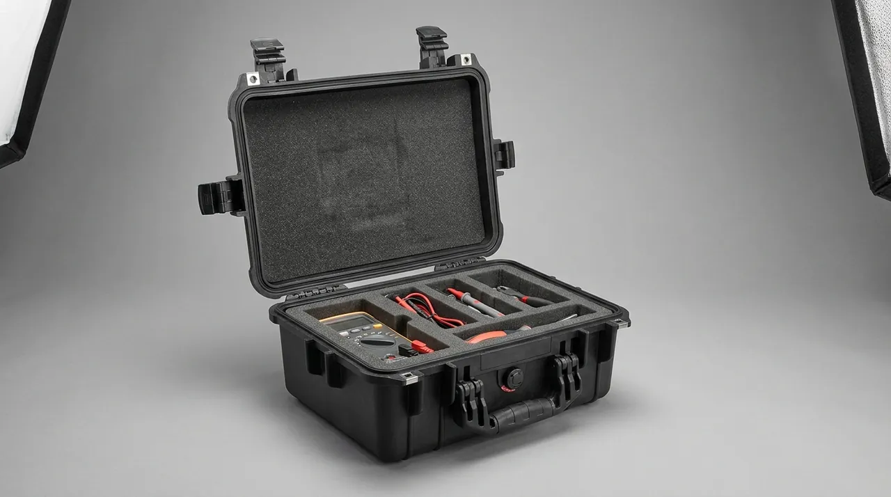
Choose 30 to 50 Shore A EVA or cross-linked PE foam for the blade seat, which balances forming accuracy against resilience. Foam softer than about 20 Shore A is not suitable, because long-distance vibration compresses it into permanent pockets and the blade loses restraint. Handling rules belong in the same document: no single-side lifting, no dropping, and storage pictograms such as keep upright and handle with care marked on the case side in accordance with GB/T 191.
6. Pump and spray system: separating impeller, shaft seal and motor
The spray pump distributes water from the sump evenly across the drum wall or the water tray. Its failure modes concentrate in three places: the impeller, the mechanical seal and the terminal box. The packaging job is to deliver all three in factory condition.
Impellers are usually bronze or engineering plastic, running with a fraction of a millimetre clearance to the housing. Impact transmitted through the housing can drive the impeller into the casing or bend the shaft, so the pump must sit against flexible insert material and must never rest on hard components. Drain the pump chamber before packing. Residual water can freeze in transit and crack a housing, or support microbial growth that contaminates the whole water circuit. Follow the drain with clean compressed air and cap the ports.
The mechanical seal relies on a lapped dynamic ring and stationary ring, and a single embedded particle causes leakage. There is no need to disassemble the seal for shipping, but the pump shaft must not see axial load, so nothing may bear on the shaft end. Upright orientation is preferred.
Terminal boxes, capacitors and thermal protectors are vulnerable to moisture and static. Pack the electrical parts in an anti-static bag with a small desiccant sachet, then fix the bag in the same cavity as the pump body. Coil the harness into a loop no smaller than about 150 mm in diameter and secure it with hook-and-loop strap rather than a cinched cable tie. Machines with a variable-frequency drive should have the controller in its own cavity and its own packaging, never sharing a compartment with metal parts.
| Component | Main failure mode | Transport cause | Packaging countermeasure |
|---|---|---|---|
| --- | --- | --- | --- |
| Pump impeller | Blade contact with casing, bent shaft | Drop impact, axial load on shaft | Flexible restraint, shaft end free |
| Mechanical seal | Face scratching, leakage | Embedded particles, axial shock | Drained and dried chamber, one part per cavity |
| Terminal box and capacitor | Ingress of moisture, lead fatigue | Humid environment, cinched harness | Anti-static bag with desiccant, large loop radius |
| Water tray and spray pipe | Tray warping, nozzle deformation | Stacking load, hard point support | Flat single layer, nozzle face up |
| Solenoid valve | Diaphragm set, open coil | Sustained compression, lead pull | Compartmented fixing, coil in own pocket |
Trays and spray pipes follow one principle: flat, single layer, nozzle face up. A warped tray loses spray uniformity and ice thickness becomes uneven across the drum; nozzles are small features that do not recover once crushed. If several trays must travel in one case, place a full-area flexible interleaf between them and support each tray independently rather than nesting them under load.
7. Food-grade piping: cleaning, drying and capping every port
Piping is the most underestimated category in an ice machine case and the one that most often ruins a first start-up. Food-grade hose, rigid pipe, tees and fittings usually come off the machine wet, and the common site practice is to wipe the outside and drop them in the case. In a hot sea container the residual water and the biofilm it feeds develop inside a closed volume, and the customer opens the case to find slimy walls and odour, then scraps the whole set and buys new pipe.
The correct sequence is five steps: clean, rinse, dry, cap, label.
- Clean. Circulate or soak with a mild alkaline cleaning agent to remove scale and organic residue. Do not soak stainless and copper parts in chlorine-based sanitiser for extended periods; chloride is a corrosion risk for both.
- Rinse. Flush with softened or purified water until the outlet water is neutral.
- Dry. Prefer oil-free clean compressed air blown end to end. Where that is not available, use heated air below 60 C for a long period; never use an open flame or a fast high-temperature bake. Hang flexible hose to drain naturally so no water collects in a bend.
- Cap. Fit clean plugs or heat-shrink caps to every pipe end, threaded port and flange. The purpose is to exclude dust and insects, not to seal in moisture, so capping must follow complete drying.
- Label. Mark each pipe with its number and installation position, mark both ends of each hose pair, and note the cleaning and drying date.
Attitude matters as much as treatment. Coil flexible hose into a loop no tighter than its minimum bend radius, commonly six to ten times the outside diameter for food-grade silicone, and never fold, flatten or cinch a hose into a sharp corner. The crease becomes a permanent attachment point for micro-organisms. Rigid pipes are best layered in installation order with all ports facing the same side so they can be taken out in sequence. When a shipment contains piping for several machines, group by machine serial and mark groups with different coloured cleanable labels. That single step shortens assembly verification on site and prevents the far more expensive error of fitting machine A's piping to machine B. Cleaning and moisture-control practice for cold chain equipment is described in cold chain food equipment cases.
8. Moisture and mould control: keeping internal humidity below the threshold
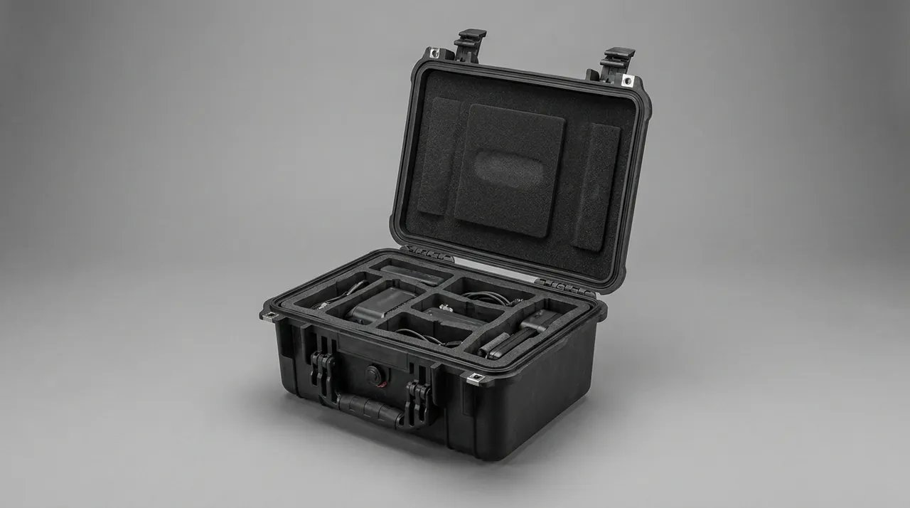
Mould needs two things: relative humidity sustained above about 65 percent, and an absorbent nutrient substrate. An ice machine component case can easily supply both, because a sea container is humid and tubing and insert surfaces may retain organic residue. Control has three levers, in priority order: remove the substrate, exclude moisture, monitor the result.
Removing the substrate means no fibrous material anywhere in contact with components, no food residue or scale left on surfaces, and dry internal bores on every hose. Do this properly and a short humidity excursion will not produce mould. Excluding moisture means a case sealed to at least IP54 as defined by GB/T 4208, which is technically identical to IEC 60529, with IP67 preferred for sea freight; a replaceable silica gel or molecular sieve desiccant sized to the internal net volume, with a common silica guideline of 1.0 to 2.0 kg per cubic metre of net volume and one step higher for long-term storage; and no large bare metal surfaces acting as condensation targets.
Monitoring relies on indicator cards and recording tags. Fix an irreversible humidity indicator card inside the lid marked at 30, 40, 50 and 60 percent so the peak humidity of the journey can be read the moment the case is opened. For humidity-sensitive or dispute-prone shipments, add a temperature and humidity logger with a 15 to 30 minute interval and deliver the data with the case.
Desiccant management is the step people skip. Once silica gel is saturated it not only stops absorbing but can release moisture back into the case as ambient humidity falls, so a replacement interval is mandatory: inspect and replace every six months in routine storage, and replace before every transfer for reusable cases. Put the replacement date and the operator's name on an external label. For long-term storage, ventilate the case every three to six months and reseal it with fresh desiccant immediately afterwards, so humid air is not sealed inside.
9. Passivated stainless surfaces and the chloride risk
Stainless steel does not avoid corrosion by being inert; it relies on a passive film that repairs itself. That film is stable in an oxygen-rich, clean, dry environment and is destroyed by oxygen depletion, chloride ions, crevice water or iron contamination. An ice machine component case can create all three of the adverse conditions at once: a closed case has limited oxygen exchange, sea air carries chlorides and condensation deposits them on surfaces, and any insert face pressed against a component forms a crevice where water can sit.
Five practical actions follow. Choose insert materials free of sulphur and chlorine and avoid low-cost recycled rubber or chlorinated foam. Design contact faces with no water-trapping recesses, or add drainage notches and low-point holes where the geometry forces a recess. Clean and wipe the drum and blade surfaces before packing to remove machining residue and hand sweat, since sweat chloride is a classic pitting initiator. Avoid grease-type rust preventives on food contact surfaces, because the oil film holds water and creates a cleaning validation burden; if protection is essential, use a food-grade removable agent and record the removal method on the packing list. Where the customer requires corrosion evidence, arrange a neutral salt spray test to GB/T 10125 for 48 to 96 hours on case hardware such as latches, hinges and lifting points, while noting that a salt spray result assesses the hardware only and does not change the food-grade status of the components.
Passivation and packaging are not substitutes for each other. A perfect passive film still loses surface roughness to a single rolling hard particle, and no packaging can repair a weld bead that was never treated at the factory. They are separate answers to the questions of outgoing condition and arriving condition.
10. Insert structure and zoning: removable modules, restraint and drainage
The insert defines every positional relationship inside the case. Because ice machine components vary widely in size and count, specify a standard base plate plus zoned modules rather than a single fully moulded cavity, so a model change or a new spare part requires only a local module replacement.
A typical zoning plan:
- Heavy zone, centre and low. Drum, motor and gearbox. Keep them near the geometric centre and the handle support points to limit eccentric loading during a carry.
- Precision zone, upper layer. Scraper blades, main shaft, water tray. No upper cavity should share a vertical projection with a heavy item below it.
- Water circuit zone, separately partitioned. Pump, valves, piping, spray pipes. Keep clear of electrical parts so residual water cannot reach live components.
- Electrical zone, away from water. Motor terminal box, controller, sensors, harness. Sealed bag or separate inner box with desiccant.
- Consumables and seal zone, individual pockets. O-rings, gaskets, plugs, fasteners. One specification per pocket with a label, so mixed parts do not force a rework.
Profile the restraint cavities to the actual outline of each component and hold the fit clearance at 0.5 to 1.5 mm. Too loose and the part migrates inside its cavity; too tight and it is scraped during loading and unloading, which damages both the passive film and any polished face. Break or radius the cavity edges so no sharp corner introduces a local stress riser.
On process, hand cutting suits one-off prototypes but has poor repeatability. CNC routing and thermoforming suit volume production and normally hold cavity repeatability within about 0.3 mm, which is what makes them appropriate for a reusable fleet case. Where several machine models share one case, a swappable module system is usually cheaper than a dedicated case per model; see the costing method in custom foam insert design guide. Mark component name, number and orientation on the insert surface. After a year in service, reading the label beats trusting memory.
11. Case selection: IP rating, latches, hinges and pressure equalization
The case must simultaneously carry stacking loads, concentrated lifting loads and a sealing duty. Confirming four parameters up front prevents most rework.
| Parameter | Recommended value | Note |
|---|---|---|
| --- | --- | --- |
| Ingress protection | IP54 minimum, IP67 for sea freight | Tested to GB/T 4208 / IEC 60529 |
| Impact rating | IK08 or better | Matched to drop height and case mass |
| Flammability | UL94 V-0 for electrical compartments | Raised requirement when electronics travel inside |
| Service temperature | -30 C to +60 C | Covers container heat and cold-climate handling |
| Seal material | EPDM or silicone | Ozone and low-temperature resistance; avoid plain nitrile |
| Pressure equalization | Recommended | Prevents vacuum lock after temperature swings |
Sealing and venting are frequently confused. The ingress rating addresses water and dust entry; the equalization valve addresses differential pressure. The better the seal, the larger the pressure difference created by a rapid temperature change, and without a vent the case can become hard to open or can draw humid outside air in the moment it is opened, cancelling the desiccant. See case seal material selection for structural options.
Latches and hinges fail first in long service and are the points at which the ingress rating is most likely to be lost after repeated cycling. Three points are worth checking: latch count matched to case volume, with at least one load-bearing point every 300 to 400 mm along the long side; hinges with metal pins, where the pin is not retained by self-tapping screws driven into a thin wall; and both latch and hinge mounting seats placed on reinforced ribs. Failure modes are described in toolbox hinge and latch structure. For after-sales spare parts cases that are opened constantly, size the handle and casters to the loaded mass so the handle does not fail before the shell does.
12. Packaging validation: GB/T 4857, ISTA and salt spray planning
Validation converts design assumptions into deliverable evidence. Three levels are appropriate for an ice machine component case.
The first level is design and material confirmation: insert profiling accuracy, contact area fraction, desiccant sizing, seal material low-temperature performance. It needs no test equipment and has the largest effect on the outcome.
The second level is laboratory performance testing. The GB/T 4857 series, aligned with the ISO 4180 approach, covers drop, stacking and vibration; export orders commonly follow the ISTA 3A or 3E sequence for full-packaged-product performance; large component cases can set severity from the ASTM D4169 distribution cycle. Referencing these standards is a validation basis only and does not constitute any certification.
| Test | Reference standard | Typical severity example | Focus |
|---|---|---|---|
| --- | --- | --- | --- |
| Drop | GB/T 4857.5 / ISTA 3A | Graded by total mass, faces edges and corners | Corner collapse, latch release |
| Random vibration | GB/T 4857.23 / ASTM D4169 | 1.0 to 1.2 g rms, 30 to 60 min per axis | Insert settling, component migration |
| Stacking | GB/T 4857.3 | Load from transport stacking height, 24 h | Shell creep, base deflection |
| Low temperature storage | MIL-STD-810H method 502 | -30 C for 24 h | Seal hardening, foam embrittlement |
| Hot humid storage | MIL-STD-810H methods 501 and 507 | +60 C at 95 percent RH for 48 h | Mould, hardware corrosion |
| Salt spray | GB/T 10125 | Neutral salt spray 48 to 96 h | Latches, hinges, lifting points |
The third level is field validation on a real route. Place shock and temperature-humidity recorders in the shipment, then compare the recovered data against the design assumptions on three questions: whether peak acceleration exceeded the absorption range the insert was designed for, whether dominant vibration energy fell near the resonance of the packaging system, and whether internal humidity crossed the 65 percent threshold in transit. Field data is what actually corrects insert thickness and desiccant quantity instead of leaving the project at the level of a passing laboratory report. See GB/T 4857 transport packaging test essentials for the underlying logic.
13. Purchasing acceptance checklist and common misconceptions
Writing acceptance criteria into the purchase contract is the cheapest way to avoid disputes later. A practical checklist covers the following.
- Measured fit clearance between insert cavity and actual components, sampled at no fewer than three locations and recorded.
- Contact form at the drum wall interface, continuous or segmented arc, with the contacted length fraction.
- Measured clearance between blade edge and any insert material in the blade slot.
- Ingress protection rating, the test method used, and whether a third-party report is provided.
- Seal material certification and low-temperature performance data.
- Desiccant type, quantity, replacement interval and number of indicator cards.
- Hardware material and surface treatment, with the salt spray duration applied.
- Labels and markings, including GB/T 191 storage and handling pictograms, case number and packing list number.
- Accompanying documents: packing list, cleaning record card and insert layout drawing.
Five misconceptions recur. First, judging a case by wall thickness instead of insert design, when restraint rather than shell gauge decides the outcome. Second, substituting a general toolbox for a dedicated insert, which saves money initially but leaves fillers doing the restraint job and creating hard contact points. Third, treating desiccant as a universal fix while ignoring tubing and insert materials, which actually drive mould growth. Fourth, capping pipe ports before cleaning and drying, which locks moisture inside. Fifth, omitting handling instructions, so site staff lift one side or tip the case the way they would an ordinary toolbox. Eliminating those five takes the arriving condition of a component case close to its outgoing condition.
Frequently Asked Questions
Q: Can the scraper blade travel in the same case as the ice drum?
A: It is not recommended. A scraper blade is a thin formed part with edge straightness commonly held to the order of 0.1 mm over 300 mm, while the drum is heavy. Even with bubble wrap between them, the drum's weight and inertia keep acting on the blade edge through the padding during a long shipment, producing micro indentations. Those marks are almost invisible during outgoing inspection but leave a strip of ice unscraped after installation, and in severe cases they excite vibration in the carrier and noise in the bearings. The correct arrangement is a dedicated blade seat inside the same case, with at least 5 mm of clear space on the cutting side so the edge touches nothing, and contact limited to the unsharpened backing face. One blade per slot, never stacked. The carrier and main shaft should travel in separate cavities with soft sleeves over the journals, and if the two must genuinely share a compartment, a rigid divider is required that never contacts the edge itself.
Q: What goes wrong if a machine's original shipping carton keeps being used for spare parts?
A: The original carton is designed for a single long journey, and its foam normally takes an unrecoverable compression set after one full shipment. Continued use causes two problems. The cavity-to-component clearance grows and restraint effectively disappears, so every later trip adds relative movement. Corrugated board also loses strength rapidly once it absorbs moisture, so stacking and lifting both become unreliable, and in a wet ice machine environment the board itself is a mould substrate. Treat the original carton as a transition package for first delivery and transfer to a reusable rigid case after acceptance. If budget is tight, at minimum fit a new insert and add a humidity indicator card. For components with food contact surfaces, long-term reliance on board is inadvisable because shedding fibres contaminate the drum wall and the blade edge. A rigid case with a replaceable insert also lets you keep a written record of cleaning dates, which a collapsing carton can never support.
Q: Why emphasise passivated surface care on stainless steel rather than ordinary rust prevention?
A: Stainless steel resists corrosion through a dense chromium oxide film a few nanometres thick, and passivation makes that film more uniform and complete. It differs from a rust-preventive coating in two important ways. The passive film is extremely thin and changes neither dimensions nor surface roughness, and although it can self-repair, it has very little resistance to mechanical abrasion, so one rolling hard particle can break its continuity locally. Protection therefore focuses on avoiding scratches and avoiding contamination rather than applying a heavy oil layer. Grease on food contact surfaces is not advisable because the film traps water underneath and adds a cleaning validation burden. In practice: choose sulphur-free and chlorine-free insert materials, avoid recesses that hold water, wipe machining residue and hand sweat off before packing, and close all ports with clean plugs. Where the customer asks for corrosion evidence, a neutral salt spray test to GB/T 10125 on the case hardware provides useful data, but it evaluates latches, hinges and lifting points rather than the drum or blade themselves.
Q: What cleaning and drying steps should food-grade pipe and pump bodies go through before packing?
A: Work through five steps: clean, rinse, dry, cap, label. Clean by circulating or soaking with a mild alkaline agent to remove scale and organic residue, and avoid prolonged soaking in chlorine-based sanitiser because chloride attacks both stainless steel and copper. Rinse with softened or purified water until the outlet is neutral. Dry with oil-free clean compressed air, or heated air below 60 C; never use an open flame, and hang flexible hose so water cannot collect in bends. Capping must follow complete drying, with clean plugs or heat-shrink caps on every pipe end, threaded port and flange, purely to exclude dust and insects. Finally label each pipe with its number, installation position and the cleaning and drying date, and mark both ends of each hose pair so assembly and traceability are straightforward on site. Coil hose no tighter than its minimum bend radius, commonly six to ten times the outside diameter, because a crease becomes a permanent attachment point for micro-organisms and can flatten the bore. Keep the pump chamber drained as well, since water trapped there can freeze in transit.
Q: How much desiccant is needed, and how do I decide when to replace it?
A: A common silica gel guideline is 1.0 to 2.0 kg per cubic metre of internal net volume, increased one step for long-term storage or an export route with high heat and humidity, with colour-indicating silica gel or a molecular sieve preferred. The most direct replacement trigger is the irreversible humidity indicator card inside the lid: if the 60 percent field has changed colour, the shipment saw a high humidity excursion, so replace the desiccant and inspect the seal. Build a replacement interval into the maintenance plan: inspect and replace every six months in routine storage, and replace before every transfer of a reusable case. Saturated silica gel not only stops absorbing but can release moisture as ambient humidity falls, so it must not be retained just because it looks dry. An external label with the replacement date and operator name makes the record auditable. Where a machine travels by sea in the summer, consider molecular sieve desiccant instead of plain silica gel, because it holds moisture more strongly across the temperature swings a container experiences.
Q: Which foam is better for an ice machine component insert, EVA or PE?
A: They do different jobs and are normally combined rather than chosen between. Use 30 to 50 Shore A EVA or cross-linked PE for the restraint layer that touches components, because it balances forming accuracy, dimensional stability and resilience. Use 25 to 45 kg/m3 PE foam for the outer cushion layer that absorbs impact energy. With only one layer, thin blade edges and polished drum surfaces should get the support of EVA, since ordinary soft foam forms permanent pockets under long-distance vibration and restraint is then lost, and those pockets do not recover. In food-grade applications also confirm the foam is sulphur-free, chlorine-free and non-shedding, and that it can be lifted out whole for cleaning and disinfection, with seams covered by a continuous sheet. Foam softer than about 20 Shore A is not advisable for blade or drum cavities. Where components are loaded and unloaded frequently, add a wear-resistant facing to extend cavity accuracy life.
Q: Which packaging validation tests should an export ice machine component case go through?
A: Plan three levels. The first is design confirmation: insert profiling accuracy, contact area fraction, desiccant sizing and seal low-temperature performance. The second is laboratory testing, following the GB/T 4857 series for drop, stacking and random vibration, the ISTA 3A or 3E sequence for export orders, and the ASTM D4169 distribution cycle approach for large component cases, with hardware corrosion assessed by a 48 to 96 hour neutral salt spray test to GB/T 10125. The third is field validation with shock and temperature-humidity recorders on the real route, comparing peak acceleration, resonance behaviour and whether internal humidity crossed the 65 percent threshold. Referencing these standards provides a validation basis only and does not constitute any certification. Actual test severity should also reflect total packed mass, the number of stacked layers and the transport mode used. Keep the test specimens and photographs with the report, because insert compression after the vibration run is often the first visible sign that the cavity profile needs adjustment.
Q: Does an ice machine spare parts case really need IP67, or is IP54 enough?
A: It depends on the route and the storage conditions, so there is no single answer. IP54 stops dust and water spray from all directions and is adequate for short domestic journeys, covered warehousing and fast turnaround. For export sea freight, IP67 is advisable: day-night temperature swings in a container cause repeated condensation, open port storage exposes the case to rain and spray, and once water enters, crevice corrosion on stainless parts and oxidation of copper parts both accelerate. Note that a higher ingress rating is not automatically better. A tighter seal increases the pressure differential and can draw humid outside air in the moment the case is opened, cancelling the desiccant, so an IP67 case should be combined with a pressure equalization valve. Seal strips also age and the rating drops after repeated cycling, so include the seal in the scheduled replacement list and inspect it at the same time as the desiccant.
Conclusion and Further Reading
Ice machine component cases succeed on three points that have nothing to do with shell thickness: holding drum roundness and blade geometry at their designed condition, keeping food contact surfaces cleanable and verifiable, and holding internal humidity below the mould threshold. Start specification from the disassembly list and check insert zoning, blade restraint, pipe treatment, desiccant sizing and validation evidence item by item.
Further Reading