

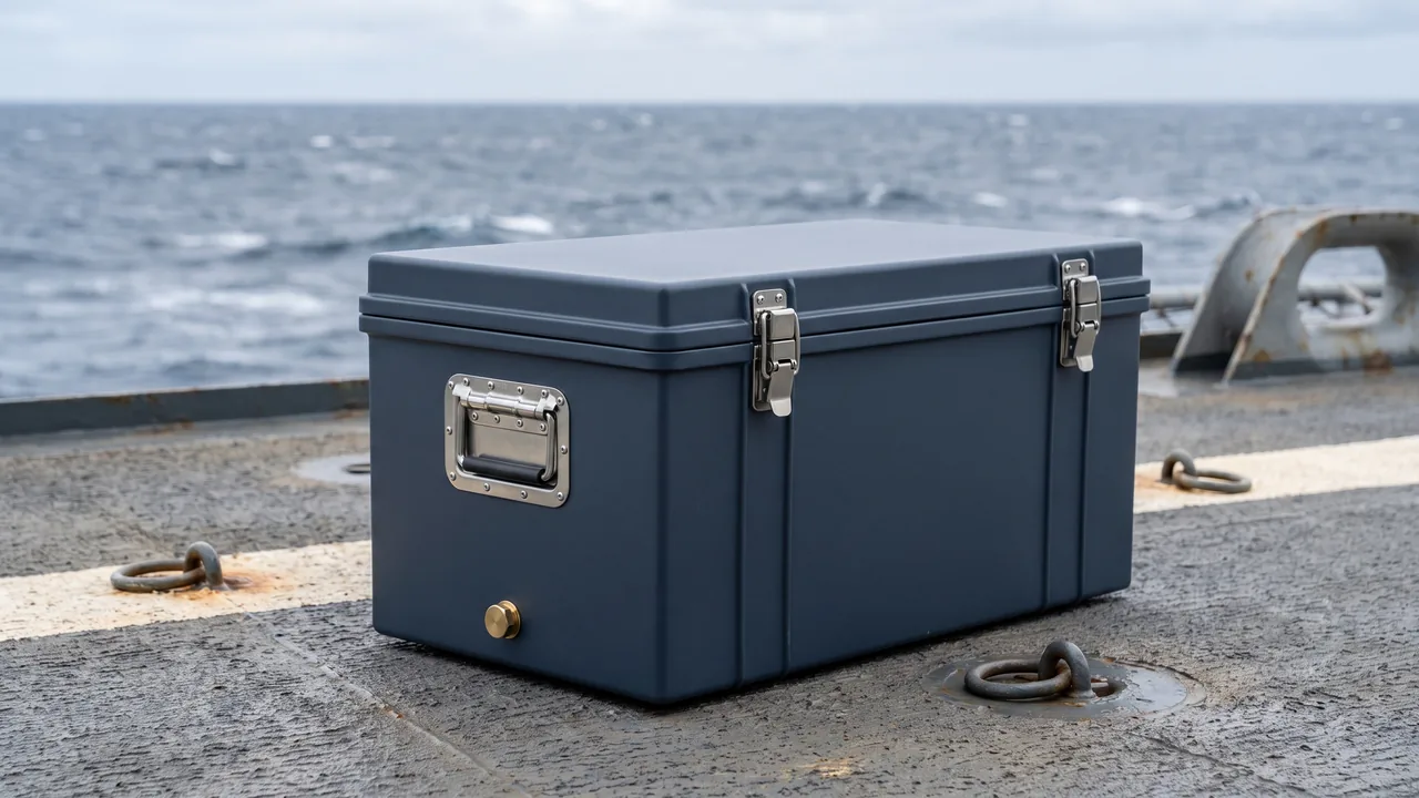
On refrigeration plant overhauls and new-build projects, the schedule is rarely set by the main skid. It is set by the compressor, the condenser and evaporator coils, the expansion valves and the control boards, because these are the items that ship separately and arrive with their own handling history. Each of these four families fails for a different reason: a compressor is damaged by load and vibration, a coil by point pressure on the fins, an expansion valve by contamination and ice blockage, and a control board by static discharge and condensation. Packing all four into one case with one generic foam set multiplies all four risks at once. Copper-and-aluminium fin packs commonly run fin spacing in the 1.5 to 2.5 mm range, and one careless stacking decision can remove a measurable share of the heat transfer area. Compressor feet and suction or discharge ports are stress risers, and a single dropped case can shift shaft alignment. MOSFET gate oxides on a control board can be degraded by electrostatic discharge in the low hundreds of volts. This article works component by component and gives case structure, liner hardness, cleanliness and moisture-control settings that can be copied directly into purchasing and acceptance documents.
The arrival sequence is usually the awkward part. The main skid is still waiting on foundation acceptance, while the compressor and coils have already landed and are sitting under an open canopy at the project warehouse for several weeks. The problem surfaces later, during evacuation, refrigerant charging or the first pull-down curve, when capacity is short or an intermittent electrical fault appears. By then the responsibility window has closed and the rework slot has been squeezed out of the programme. Moving protection requirements upstream into the packaging review, and moving acceptance to the moment the case is opened, is the practical problem this article addresses.
Contents
- Why refrigeration components fail so often in transit
- Compressors: load control at the feet, ports and oil level
- Condenser and evaporator coils: the no-pressure boundary on fins and tubing
- Expansion valves and metering parts: sensing bulbs, capillaries and internal cleanliness
- Control boards and electrical modules: ESD protection and condensation control
- Refrigerant system cleanliness: ISO 4406 and port capping
- Moisture control: desiccant sizing, humidity indication and pressure equalisation
- Vibration design: liner hardness, location blocks and resonance avoidance
- Case structure and stacking: frame, pallet and stack height
- Lifting and site transfer: lift points, centre-of-gravity marking and access
- Test and verification basis: ISTA, GB/T 4857 and MIL-STD-810H
- Marking, shipping documents and the opening inspection
- Selection checklist and five common mistakes
- Frequently asked questions
- Conclusion and related reading
Why refrigeration components fail so often in transit
A mid-sized refrigeration package has a long list of separable parts: a semi-hermetic screw or scroll compressor, an oil separator, a receiver, an air-cooled finned coil or a water-cooled shell-and-tube heat exchanger, electronic and thermal expansion valves, filter driers and sight glasses, solenoid valves, pressure and temperature sensors, a variable-frequency drive and a main controller board. These travel in three legs: factory to distributor warehouse, distributor warehouse to project site, and site temporary store to the plant room door. The first two legs are usually under professional logistics control. The last leg is the shortest, the least supervised and the source of most damage.
Field returns cluster into five patterns. The first is crushed vibration isolators and plastically deformed compressor feet, which show up as higher pipe stress, elevated running vibration and, in worse cases, shaft misalignment. The second is collapsed fins and flattened copper tubes. Visually this is dismissed as cosmetic scuffing, but the air-side pressure drop rises and the heat transfer area falls, so commissioning shows short capacity and unstable superheat, and the first suspect is usually the refrigerant charge. The third is contamination inside expansion valves and deformed capillaries. Debris collects at the valve port as a blockage, while moisture freezes after the expansion point as an ice blockage; the two look similar on site but need entirely different responses. The fourth is electrostatic damage and condensation on control boards, which typically appears as intermittent communication loss or drive faults, sometimes not at all during first power-up. The fifth is moisture ingress into the refrigerant circuit, where water reacts with the lubricant to form acids and the compressor insulation resistance drops; the eventual cost is a compressor.
All five share one timing characteristic: they almost never appear on the day of delivery. Collapsed fins can be seen but are hard to classify as a defect at the receiving dock. A few tenths of a millimetre of compressor foot deformation looks completely normal, and only shows up when vibration is measured at full load. The value of a component case is therefore not visual bulk. It is that the part still holds its factory geometry, surface condition and internal cleanliness at the instant the lid comes off.
Compressors: load control at the feet, ports and oil level
The compressor is the heaviest, highest-centre-of-gravity and least tolerant item in the case. Scroll and semi-hermetic screw feet are usually castings. They carry vertical compressive load well but are sensitive to lateral bending and single-point impact. Once a foot deforms, the relative position of compressor and piping changes, residual stress builds at welds, and the failure appears later as a cracked line.
Attitude control comes first. Most models must travel upright, with any permitted tilt limited to the manufacturer's stated angle; as a rule of thumb, long-term tilt should be kept small, otherwise lubricant migrates into the compression chamber or the oil level switch reads incorrectly. Impact during lifting and landing needs the same attention. The feet are not lift points. Use the factory lifting eyes or a properly rated sling under the body, and never let the case drop freely onto the ground.
Suction, discharge and service ports need factory blanking plates or dedicated plugs, secured against loosening. Rubber and plastic plugs creep out under vibration. If a plug falls out in transit, ambient moist air enters the shell directly; the lubricant absorbs moisture, acid value rises, and evacuation cannot fully recover the situation. Vibration isolators, spring mounts and foot bolts should be removed and packed separately. Rubber under continuous compression takes a permanent set, so refitted isolators transmit more vibration than intended, which is a common root cause of high running noise.
| Typical defect | Main cause | Consequence |
|---|---|---|
| --- | --- | --- |
| Plastic deformation of feet | Lifting on the feet, landing impact, no lateral restraint | Shaft misalignment, concentrated pipe stress |
| Abnormal oil distribution in the shell | Long-term tilt, inversion, repeated rocking | Poor start-up lubrication, false oil-level trips |
| Port plug ejected | No anti-loosening feature, vibration creep | Moist air ingress, lubricant acidification |
| Crushed vibration isolators | Stored compressed in the same compartment, high temperature | Reduced isolation, higher running vibration |
| Loose terminal box connections | Unsecured harness, inertial pull | Rising contact resistance, phase loss and overheating |
For export spares or long road legs, the compressor should occupy its own compartment with stiff location blocks on all sides, so that displacement in any direction is taken by the blocks rather than by refrigerant lines or the terminal box. When JUNZHIJIA scopes a compressor spare case, the starting inputs are the model, the centre-of-gravity height, the foot hole pattern and the permitted transport tilt angle. The block positions and the base bearing plate thickness follow from those numbers, rather than from a generic case size.
Condenser and evaporator coils: the no-pressure boundary on fins and tubing
The coil is the most delicate load in the case. Aluminium fin stock commonly runs 0.10 to 0.15 mm thick with 1.5 to 2.5 mm fin spacing, which means the finned section has essentially no compressive capacity. Any point or line load landing on the fin field collapses it, and collapsed fins cannot be restored to their original face area and airflow pattern by simple straightening.
There is really one governing rule: all support forces must act on the end plates, tube sheets, headers and frame sections, never through the fin field. Everything else follows. Do not place soft padding against the middle of the fin field. Do not strap around the centre of the coil. Do not lay a coil underneath another heavy item. Do not use the connecting copper lines as a support point.
Coil orientation should follow stiffness. An air-cooled coil is typically two end plates with intermediate support plates; the long axis is relatively stiff and the short axis is not. The practical answer is multiple conforming cradles across the short direction, with cradle spacing tied to the fin length and normally kept within twice the support plate pitch. Standing coils need anti-toppling restraint; lying coils need support that prevents the tube rows from bowing under their own weight. For long coils, add a mid-span divider inside the case so that the long span is broken into two.
| Component | Sensitive feature | Recommended protection | Prohibited practice |
|---|---|---|---|
| --- | --- | --- | --- |
| Air-cooled finned coil | Aluminium fins, fin pitch, tube rows | Load on end plates, conforming cradles, corner protection | Direct force on fins, strapping at mid-span |
| Shell-and-tube exchanger | Nozzle flanges, end cover seals | Protective film on flange faces, axial restraint | Using nozzles as supports, stacking loads |
| Copper return bends and headers | Bend radius, brazed joints | Individual saddles, limited swing | Lifting on return bends, mutual stacking |
| Stainless end plates | Surface scratches, passive layer | Film plus board separation | Direct contact with carbon steel parts |
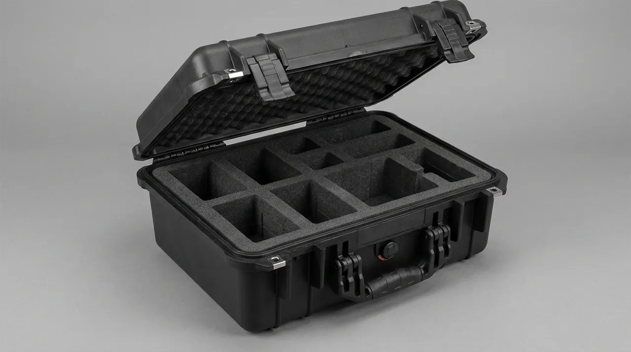
Nozzle and port protection matters just as much. A scratched or pitted flange face becomes a leak path once assembled. Ports should carry caps, and connecting copper lines should be capped at the open end and restrained to an internal bracket rather than left as a free cantilever that fatigues under vibration. Material separation is the third point: aluminium and stainless steel in contact in a damp environment form a galvanic couple, so an inert membrane or board must sit between them. For conforming cradles and compartment liner design, see custom insert structural design and material selection.
Expansion valves and metering parts: sensing bulbs, capillaries and internal cleanliness
Expansion valves are small, so they get dropped into a case as loose items. They are actually the highest-precision and most contamination-sensitive parts of the circuit. A thermal expansion valve regulates superheat from the pressure change in the charge inside its sensing bulb, so the way the bulb is strapped and the route the capillary takes both affect regulation. An electronic expansion valve pairs a stepper motor with a needle at very small clearance, and any particle can cause it to stick.
Capillaries take the most abuse in packing. The bend radius must stay above the manufacturer's minimum. Never kink a capillary, never let it bear against a case edge, and never bundle it with heavy items. A single kink changes the metering characteristic, and on site the symptom appears as high superheat, which is an expensive fault to trace back. Sensing bulbs should keep their factory strap or clamp intact; do not dismantle them for packing convenience.
Internal cleanliness has to be expressed as concrete actions. Valves normally ship with plastic caps or sealed packaging, and they should stay sealed in the case. If inspection requires opening them, reseal on a clean bench rather than leaving them open in a general warehouse. Solid-particle cleanliness in refrigerant systems is commonly described by ISO 4406 cleanliness codes. Filter driers, sight glasses and solenoid internals are clean components by definition and should be stored apart from bare metal parts.
| Metering and valve part | Primary sensitivity | Packing action |
|---|---|---|
| --- | --- | --- |
| Thermal expansion valve | Sensing bulb charge, capillary routing | Keep factory strapping, coil capillary at large radius |
| Electronic expansion valve | Stepper motor, needle clearance | Separate valve body and coil, ESD bag packaging |
| Filter drier | Moisture saturation, seal integrity | Keep factory seal, desiccant sized per item |
| Sight glass | Glass window, seal ring | Individual compartment, window up, protective ring |
| Solenoid valve | Coil, diaphragm, return spring | Coil and body packed apart, avoid set under power |
Unlike compressors and coils, metering parts fail almost entirely through detail rather than mass. Give them individual small compartments in the case, sized one step above the part envelope, lined with a relatively soft closed-cell material so the parts cannot collide or migrate under vibration, and hard enough not to create a pressure point on a corner.
Control boards and electrical modules: ESD protection and condensation control
For control boards, variable-frequency drives, touch panels and sensors, transport protection reduces to two things: static discharge and humidity. Electrostatic damage is exceptionally hard to see. A MOSFET gate oxide can be punctured or partially damaged by a discharge in the low hundreds of volts. A partially damaged device does not fail immediately; it degrades through thermal cycling and humidity change, and presents weeks later as an intermittent fault.
The packing actions are well defined. Boards go into metallised shielding bags, not pink anti-static bags alone. Boards are separated by conductive foam or anti-static dividers so that rubbing cannot generate charge. The case as a whole is bonded or marked for grounding according to the applicable procedure. Operators at the receiving end wear grounded wrist straps. Modules containing lithium cells, memory cards or radio units need their own restraint and, where relevant, the general requirements for battery transport.
The difficult part of moisture control is the trade-off between sealing and breathing. A fully sealed case produces internal condensation through day-night temperature swings, which on a sea container can span more than ten degrees Celsius. A fully open case cannot keep moisture out at all. The engineering answer separates pressure from vapour: a pressure equalisation valve lets the differential bleed off slowly, a desiccant absorbs residual moisture, and a humidity indicator card gives the receiving team something to read. For valve selection logic, see how a case pressure equalisation valve works.
| Electrical part | ESD-sensitive feature | Packing requirement |
|---|---|---|
| --- | --- | --- |
| Main controller PCBA | Gate oxide, CMOS inputs | Metallised shielding bag, conductive foam separation |
| Variable-frequency drive | Power devices, DC-link capacitors | Dedicated compartment, secured terminal covers |
| Touch panel and display | Glass face, ribbon cable | Rigid face protector, ribbon coiled at large radius |
| Pressure and temperature sensors | Diaphragm, signal lead | Factory packaging, no vibration fatigue |
| Terminals and harnesses | Plating, latches | Terminal caps, harness restrained against pull |
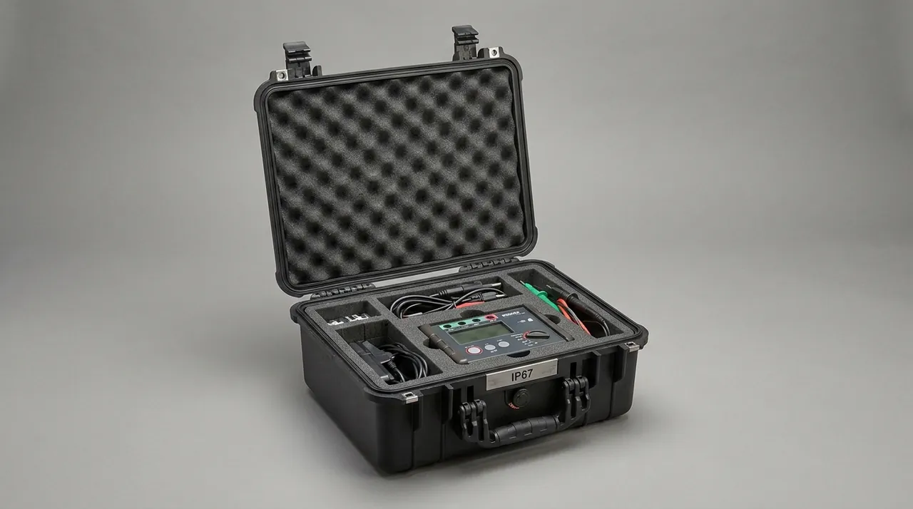
For the full set of ESD structures and materials, including surface resistance ranges and grounding practice, see ESD shielding case structures and material options. In electrical compartment scopes, JUNZHIJIA normally sets liner material and shielding layer from the customer's device sensitivity class under the human body model and charged device model, and states the opening procedure in the shipping documents so that a technician does not lift a board bare-handed.
Refrigerant system cleanliness: ISO 4406 and port capping
Refrigerant circuits carry solid-particle and moisture limits through their whole service life, and the transport window is where contamination most often gets in. Site cutting, grinding and construction dust all find an open pipe. A connecting line set down on the floor picks up dust and moisture within minutes.
Capping open ports is the cheapest and most effective action available. Every opening should take a dedicated plug, cap or tape-and-tie closure. Do not use paper wads, rag strips or wooden plugs. The closure itself must not be able to fall into the pipe, so flanged push-on caps are preferred over push-in plugs. Parts already charged with dry nitrogen should hold pressure with the value recorded; parts under vacuum should hold vacuum with an indicator fitted. If residual lubricant is present, confirm that no oil is weeping before capping, and clean any oil film.
Cleanliness can be written into acceptance documents as a number. Circuit cleanliness is commonly stated as an ISO 4406 particle count code, and projects set different target classes. A packaging scheme does not change system cleanliness, but it determines whether the part still holds factory cleanliness on arrival. Two clauses are worth adding to purchase documents. First, transport packaging must guarantee that all port closures remain in place and intact. Second, the replacement interval for closures, desiccant and humidity indicator cards, together with the opening inspection steps, must be stated in the shipping file.
Preventing closure failure matters as much as the closures themselves. Vibration walks plugs out, especially tapered plastic ones. The practical fix is a layer of anti-loosening tape over the cap, plus arranging port orientation toward the case wall so the port cannot swing freely. For long connecting lines, add pipe clamps that tie the line to the case frame so it cannot move relative to the case.
Moisture control: desiccant sizing, humidity indication and pressure equalisation
Refrigeration components have higher moisture sensitivity than general machinery, because three different areas dislike water. Finned aluminium and copper suffer galvanic corrosion and verdigris. Control systems suffer condensation short circuits and electrolytic corrosion. The refrigerant circuit suffers water reacting with lubricant to form acid. Moisture control therefore has to be layered rather than reduced to dropping in a few desiccant bags.
The first layer is the barrier capability of the case itself. The seal structure, meaning the gasket and the mating faces at hinges and latches, sets the rate at which external moisture enters. Compression design and material selection for that layer are covered in case seal material selection and compression design. The second layer is desiccant sizing, calculated from free internal volume, transit duration and target humidity rather than from habit. The third layer is indication, using a humidity indicator card to record the peak humidity seen, so acceptance has evidence behind it. The fourth layer is pressure equalisation, giving the case a controlled breathing path so that pressure and temperature changes do not force the gasket open or pull it inward.
| Moisture layer | What it acts on | Configuration point | Failure mode |
|---|---|---|---|
| --- | --- | --- | --- |
| Case barrier | All components | Gasket compression, mating face flatness | Gasket set, vapour through gaps |
| Desiccant | Free internal air | Sizing by volume and duration, split bags | Saturated desiccant, card colour change |
| Indication | Acceptance evidence | Humidity indicator card, peak label | No record, no basis for liability |
| Pressure equalisation | Seal structure | Micro-venting valve, orifice size and position | Gasket sucked open, heavier condensation |
Sea freight needs extra physical separation. Place a moisture barrier liner inside the case, or use a foil-laminate bag, so parts never touch a case wall that may condense. The case should sit on a pallet rather than directly on a container floor or open ground, so air can move underneath. For spares stored long term, mark the desiccant replacement date on the outside and inspect on a fixed interval.
Vibration design: liner hardness, location blocks and resonance avoidance
Among refrigeration components, compressors and coil pipework are most exposed to vibration fatigue, valve parts to wear from higher-frequency excitation, and control boards to board-level resonance. The goal is not to clamp parts rigidly. It is to keep relative motion between part and case inside a safe band while the liner dissipates excitation energy.
Liner hardness has to match mass. Closed-cell EVA and PE cover a range from soft conforming layers to stiff bearing layers. The general rule is a harder material under the base of a heavy item for bearing, a softer material at the contact face for conformity, and the two combined rather than one hardness for everything. Compression ratio matters equally. Too little compression and the part migrates inside the case; too much and the liner takes a permanent set and transmits more vibration. As an engineering rule of thumb, the conforming layer should be sized with a modest compression allowance, enough to generate stable restraint without approaching the material's dense state.
Location design separates permitted motion from prohibited motion. Directions where movement is acceptable get clearance filled with soft material. Directions where movement is prohibited, particularly the compressor tilt axis and the coil fin plane, get rigid location blocks so impact load is taken by the blocks, passed into the case frame and on to the pallet, bypassing the component body.
| Vibration source | Typical frequency character | Affected items | Mitigation |
|---|---|---|---|
| --- | --- | --- | --- |
| Road transport | Low-frequency road input | Compressor feet, pipework | Rigid base support, multi-point location |
| Sea passage | Low-frequency roll and pitch | Whole-package displacement, stacking | Lashing, reduced stack height |
| Rail marshalling | Transient shock | Coils, electrical parts | Cushioning layer, independent compartment |
| Handling drop | Narrow-pulse shock | Case corners and edges | Corner protectors, ribs, suspended liner |
One clarification on standards. MIL-STD-810H should be cited as an environmental test method basis, used to build a sensible test profile, and never as a claim of military certification. For commercial refrigeration spares, the more common references are the ISTA series and the GB/T 4857 series.
Case structure and stacking: frame, pallet and stack height
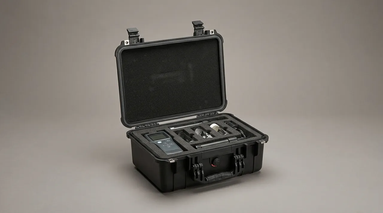
A component case has to satisfy three constraints at once: bearing load, resisting deformation, and surviving repeated opening and closing. Bearing load is carried by the base plate and frame. Deformation resistance comes from wall stiffness and internal dividers. Durability of repeated opening comes from hinges, latches and gasket life. Weakening any one of the three shows up on site as a case that stops working after two uses.
The frame should be checked by load path. In the ideal case, stack load passes from the upper case's base corners directly into the lower case's corner posts, then to the pallet and the floor, without travelling through the liner or the protected part. Corner posts are therefore essential rather than optional. For heavy items such as compressors, add an independent internal bearing divider so the compressor mass lands on the divider rather than on the conforming liner.
Hinge and latch reliability is routinely underestimated. Spare-part cases get opened and closed repeatedly on site, sometimes partially opened and resealed, and a latch that jams in cold or damp conditions invites a pry bar, which then damages the case and the sealing face. Pre-tensioned latches plus weather-resistant hinge and latch interfaces extend the service life of the case considerably; see toolbox hinge, latch and seal structure options.
| Case area | Primary load | Design point | Common failure mode |
|---|---|---|---|
| --- | --- | --- | --- |
| Base bearing plate | Component weight, shock | Thicker plate, ribs, pallet integration | Mid-span sag, edge cracking |
| Corner posts | Stack load | Continuous posts, aligned top to bottom | Post misalignment, case skew |
| Side walls | Lateral impact | Adequate stiffness, no bulging | Bulge prevents gasket contact |
| Hinges and latches | Repeated cycles, pull load | Pre-tensioned latches, weather-resistant surface | Jamming, latch tongue fracture |
| Gasket | Vapour barrier | Correct compression, replaceable | Set marks, debonding, ageing |
Stack height should be confirmed by structural test on the case rather than decided in the warehouse. As a working practice, mark the permitted stack count and the up direction on the case exterior, and mark total weight on the pallet, so a forklift operator is not judging by appearance.
Lifting and site transfer: lift points, centre-of-gravity marking and access
The last hundred metres on site are usually the least controlled: temporary labour, improvised rigging, narrow access. The case design should therefore tolerate the worst realistic handling.
Lift points belong on the frame or on dedicated lifting eyes, and they should be clearly marked. Slinging around the middle of the case is not acceptable. The centre of gravity should be marked on the case side, which matters most for compressor-heavy builds because it predicts the tilt during lifting. Fork pockets should be positioned so that the centre of gravity sits between the forks, and a wear strip under the base prevents the forks from cutting through.
Where tall components such as long coils or shell-and-tube exchangers must travel upright, mark the case with an up-arrow and state the reason, and add internal anti-toppling support so that a brief period on its side does not impose bending on the component.
Test and verification basis: ISTA, GB/T 4857 and MIL-STD-810H
Verification should reference executable test methods rather than a general claim of passing vibration testing. Common references include the ISTA series for transport packaging, the GB/T 4857 series for basic transport package tests, ASTM D4169 for distribution cycle performance testing, and GB/T 4208 or IEC 60529 for ingress protection confirmation. Environmental methods may follow the relevant sections of MIL-STD-810H, with the explicit note that this is a methods reference and not military certification.
| Reference | Applicable scenario | Typical use in this project |
|---|---|---|
| --- | --- | --- |
| GB/T 4857 series | Domestic road-dominated distribution | Vibration, shock, stacking and drop tests |
| ISTA series | International logistics and parcel chains | Distribution cycle and vehicle simulation |
| ASTM D4169 | North American distribution | Combined test sequence by distribution cycle |
| GB/T 4208 and IEC 60529 | Case sealing performance | IP rating confirmation |
| GB/T 191 | Package handling pictorial marks | Centre of gravity, keep dry, do not overturn |
| MIL-STD-810H | Environmental test methods | Test profile for temperature, humidity, vibration |
One caution: test the loaded case, not an empty one. An empty case can pass vibration and still develop a new resonance once components change the mass distribution. Run one test with simulated ballast at the proposal stage, and one spot check with real components before series delivery.
Marking, shipping documents and the opening inspection
Marking exists so that someone unfamiliar with the equipment handles it correctly. Following the pictorial requirements of GB/T 191, at minimum the case should carry centre of gravity, keep dry, do not overturn, maximum stack count and fragile-area marks. Where lifting is involved, mark the lift points and the permitted sling angle. Cases containing electrical parts should carry an ESD handling notice.
Shipping documents should include at least a packing list with item-by-item quantities, a statement of protective state covering port caps, desiccant and the initial humidity indicator reading, the permitted stack count and lifting requirements, and an opening inspection checklist. For spares stored long term, add the desiccant replacement interval and the resealing requirement.
The opening inspection is best fixed as a short sequence. Check that the exterior and markings match the packing list. Confirm that port caps are present and intact and that ports are free from contamination. Read the humidity indicator card. Inspect each item for collapsed fins, deformed copper tubing, foot and isolator condition, and the integrity of shielding bags over control boards. Then photograph and file, and sign the acceptance record. Writing these steps into a contract annex is what converts packaging spend into traceable delivery quality.
Selection checklist and five common mistakes
Work through the following items before releasing a case design.
| Check item | What to confirm |
|---|---|
| --- | --- |
| Component list and masses | Item weights, centre-of-gravity position, total mass and envelope |
| Attitude requirement | Permitted tilt angle, whether overturning is prohibited, factory transport attitude |
| Support and restraint | Whether all bearing surfaces land on end plates, tube sheets, feet or frame |
| Liner combination | Bearing layer and conforming layer hardness, compression allowance |
| Cleanliness and moisture | Port capping method, desiccant quantity, humidity indication |
| Static protection | Shielding bag type, grounding, opening procedure |
| Case structure | Corner posts, bearing divider, hinge and latch durability |
| Marking and documents | Pictorial marks, packing list, acceptance checklist, stack count |
Five mistakes are worth naming. Mistake one: laying a coil underneath a heavy item and assuming soft padding makes it safe. Padding spreads a small-area load but cannot change what the fin field can bear; force must travel through end plates and tube sheets. Mistake two: shipping compressors and valve parts in the same compartment. Small migration of a heavy item is continuous hammering for a valve part. Mistake three: fully sealing and evacuating a case for moisture control. Vacuum packaging is harmful to boards with electrolytic capacitors and does nothing about condensation driven by temperature swings; use pressure equalisation with desiccant instead. Mistake four: leaving vibration isolators fitted to the compressor during transit. Permanent set quietly reduces isolation performance. Mistake five: treating an empty-case vibration pass as complete verification. Loaded mass distribution is different, so the test must run with ballast or real components.
Frequently asked questions
Q: What is the single biggest difference between a refrigeration compressor case and an ordinary equipment case?
A: The difference is in what the load path is designed to achieve. An ordinary case aims to prevent visible impact damage. A compressor case aims to preserve the geometry that left the factory. The feet tolerate only fractions of a millimetre of deformation, and that deformation is invisible on arrival. The case must therefore route self-weight, stacking load and impact entirely into the feet and the case frame, and never allow the shell, refrigerant lines or terminal box to carry any of it. In practice this means lifting on factory eyes rather than on the feet, fitting an independent internal bearing divider so compressor mass lands on the divider, placing rigid location blocks on all four sides so displacement is taken by the blocks, and removing vibration isolators and spring mounts for separate packing so they cannot take a permanent set. Confirm the manufacturer's permitted transport tilt angle as well, because most models must stay upright. Where several compressors ship together, give each its own compartment.
Q: Collapsed aluminium fins on a condenser or evaporator coil: can they be straightened on site?
A: Straightening should not be treated as the standard remedy. Aluminium fin stock typically runs 0.10 to 0.15 mm thick, and once fins collapse, even a fin comb cannot restore the original spacing uniformity or airflow pattern. The combing process itself tends to tear fins and cause secondary collapse. More importantly, collapse is often accompanied by tube row displacement or loosening at the fin-to-tube expansion joint, and that kind of damage shows up later as rising contact thermal resistance, with capacity loss but a normal appearance. The correct order of assessment is to establish the collapsed area and depth first, then decide from heat transfer performance whether the coil must be replaced, rather than combing and hoping. Prevention is far cheaper than repair, and one rule prevents most of it: all support and restraint forces act on end plates, tube sheets and headers, the fin field takes no point or line load, and nothing is ever strapped across the coil centre or stacked on top of it.
Q: Why do small parts such as expansion valves and filter driers need separate compartments instead of being mixed together?
A: Mixing saves case volume and multiplies commissioning cost. Expansion valves and filter driers are precision metering and moisture-absorbing components. A thermal expansion valve regulates superheat from pressure change in the sensing bulb charge, so a crushed bulb or a kinked capillary shifts the regulation characteristic, and on site this appears as unstable superheat that is very hard to trace. A filter drier contains hygroscopic material, and once its seal is broken or it sits open in a damp environment, it approaches saturation before installation and stops protecting the circuit. An electronic expansion valve pairs a needle with a stepper motor at very small clearance, and particles alone can make it stick. Separate compartments deliver three things: no collision with hard metal parts, intact factory seals or shielding packaging, and an item count and condition that can be verified compartment by compartment at opening. For a buyer, the incremental cost of a compartmented liner is well below the cost of one ice or debris blockage investigation on site.
Q: Why is electrostatic damage to a control board so hard to detect at goods-in inspection?
A: Because electrostatic damage frequently leaves a partially degraded device rather than a dead one. A MOSFET gate oxide may be locally damaged by a discharge without a complete breakdown. At normal temperature and humidity the device still works, and only after thermal cycling, humidity change or extended operation does leakage current rise and present as an intermittent fault such as communication dropout, drive fault or parameter drift. This behaviour will not reproduce in a few minutes of power-up testing at goods-in, and it typically appears weeks into operation, which makes liability hard to assign. A workable combination of protection and inspection looks like this: boards always go into metallised shielding bags, never pink anti-static bags alone; boards are separated by conductive foam or anti-static dividers so rubbing cannot generate charge; cases containing electrical parts carry a grounding mark; the shipping file states the opening procedure, requiring a grounded wrist strap and forbidding bare-handed handling; and the acceptance record keeps the shielding bag seal state plus opening photographs. These steps cost very little and convert an argument into a traceable record.
Q: How should moisture protection be configured for a sea-freight export case of refrigeration components?
A: Build it in four layers rather than relying on desiccant alone. The first layer is the barrier capability of the case, governed by gasket compression design and mating face flatness; this sets the rate at which outside moisture enters and is the most important of the four. The second layer is quantified desiccant, sized from free internal volume, transit duration and target humidity, and split into several bags distributed through the case instead of piled in one corner. The third layer is indication, using a humidity indicator card that records the peak humidity at opening, which gives acceptance an objective basis and establishes which leg of the journey was responsible if a dispute arises. The fourth layer is pressure equalisation, because temperature and pressure changes over a sea passage create a differential that can pull a gasket open or produce condensation on the inner wall as temperature falls, so a controlled venting path is needed to let the differential equalise slowly. Also palletise the case so it never sits directly on a container floor or open ground, and for long-term spares mark the desiccant replacement date and the resealing requirement on the outside.
Q: How should liner hardness be chosen, and is softer always safer?
A: No. A liner that is too soft produces two problems: heavy items migrate under vibration and repeatedly strike the case wall or neighbouring parts, and the material compresses permanently so restraint decays during the journey. A liner that is too hard is equally harmful, because impact energy cannot be absorbed and passes straight into feet, pipework and boards. The sound approach is a composite rather than a single hardness. The base bearing layer uses a relatively hard material to carry weight and spread load into the bearing divider. The contact layer uses a relatively soft material for conformity and vibration dissipation. The two are bonded or mechanically combined so they cannot slide against each other. Compression allowance matters as much as hardness: the conforming layer needs enough compression to generate stable restraint, but not so much that it approaches the dense state. In practice, supply the component mass, centre-of-gravity position and transport mode, take a liner recommendation from the case supplier, and confirm it with one vibration and shock run on a ballasted case before series delivery.
Q: Which inspection points are most often missed when accepting a refrigeration component case?
A: Four come up repeatedly. The first is port closure integrity, covering compressor suction and discharge ports, coil connections and valve interfaces. If a cap has partly walked out and nobody notices, the moisture problem only appears at evacuation. The second is the humidity indicator card, which many receiving teams ignore because they only look at the hardware, thereby discarding the one objective record of storage conditions. The third is the quantity and condition of vibration isolators and accessories, because permanent set in rubber is hard to judge visually and needs a count against the packing list plus an elasticity check before installation. The fourth is the seal state of shielding bags over control boards; a bag punctured in transit loses both static and moisture protection while the board looks completely normal. Turn the opening inspection into a fixed checklist with photographic records and a joint signature. That surfaces problems early and also provides evidence if a dispute arises.
Q: What support does JUNZHIJIA provide for custom refrigeration component cases?
A: JUNZHIJIA builds customised schemes around component type and transport mode, covering liner structure, compartment layout, cleanliness and moisture configuration, and case structure confirmation. Specific work includes base bearing dividers and rigid location blocks set from compressor model and centre-of-gravity position; conforming cradles and mid-span dividers positioned from coil end plate and tube sheet geometry; individual compartments, shielding bags and anti-static liner materials for valves and electrical parts; desiccant sizing and humidity indication set from transit duration and target humidity; and pictorial marking for centre of gravity, keep dry and do not overturn in line with GB/T 191. OEM and ODM cooperation is available, with tooling from customer drawings or physical samples, or modification of liner and hardware configuration on an existing case platform. Test reports and inspection documents can accompany the scheme for purchasing review and handover acceptance, and model-based case records can be maintained for repeat orders.
Conclusion and related reading
The point of a refrigeration component case is not bulk but separation of risk. Compressor attitude, the no-pressure boundary around coil fins, capillary geometry in metering parts, and static plus moisture control for electronics each need their own answer. Put those answers in the purchase clauses and the acceptance checklist. Related topics: industrial chiller cases, air compressor parts cases, cold chain food cases.
Related Reading