

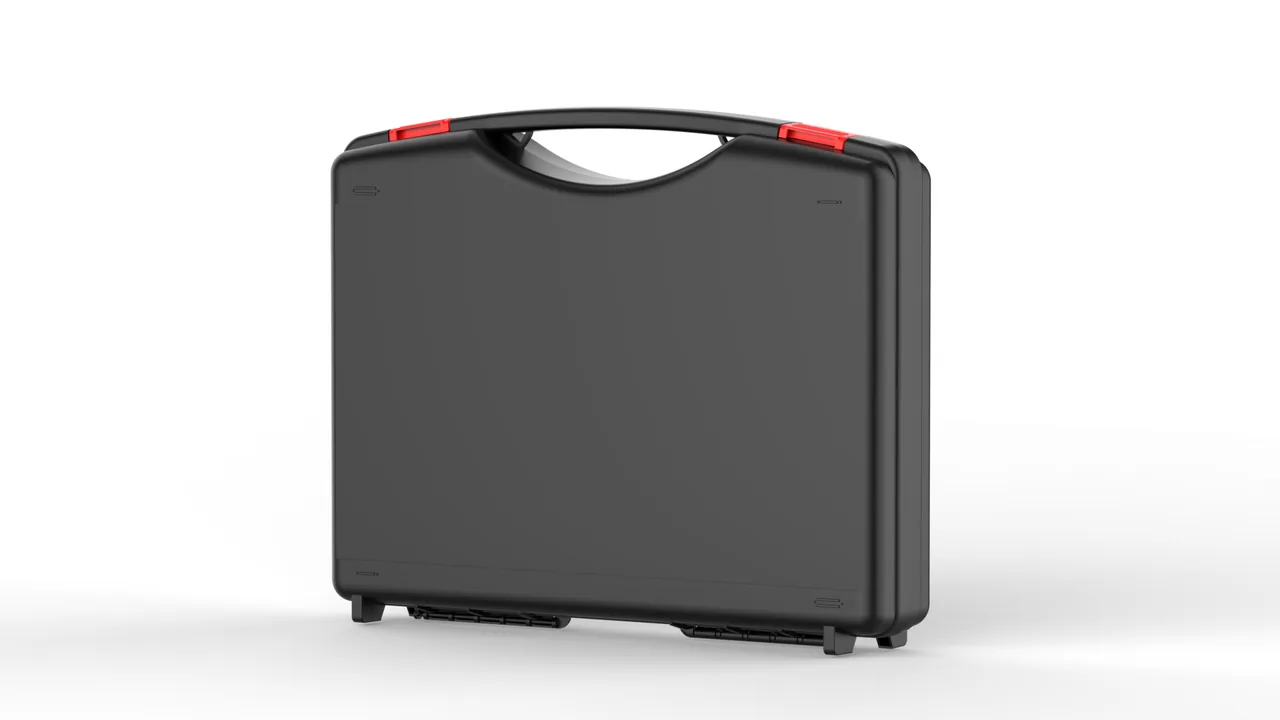
A cutter wheel only becomes cargo on the day it comes off the machine. A machine brought in for overhaul surrenders its cutters one seat at a time, and a main bearing overhaul separates inner ring, outer ring and seal stack into individual pieces. These components often sit in a shed for two or three months while the remaining overhaul parts are gathered, and by the time they are booked onto a shipment they have already been pushed out of the rain canopy into an open yard. A segment from an eight-metre cutter wheel leans diagonally against a rack. Disc cutter cases are crushed under a steel plate somebody laid on top. The corrosion inhibitor film on the main bearing has a forklift tine through it.
JUNZHIJIA protection principle for shield components: decide the split boundary first, the cushioning direction second, and only then the case. A cutter wheel, a disc cutter and a main bearing are three fundamentally different items. The wheel is a welded steel structure of tens of tonnes that fails by distortion rather than puncture. The disc cutter fails by edge chipping. The main bearing fails by seal degradation and rust transfer. Putting all three into one generic case is the most common and most expensive mistake in this industry. This article works through the failure mechanism of each, then derives the segmentation plan, material comparisons, cushion thickness logic and receiving acceptance criteria.
Table of Contents
- Cutter Wheel Plate: Spoke and Ring Segment Boundaries
- Aperture Ratio and Cutter Layout Logic
- Chipping Mechanism of Disc Cutter Carbide Edges
- Weld Deformation Stress Concentration at Cutter Seats
- Leak Paths of Multi-Lip Main Bearing Seals
- Gear Tooth Surface Pitting and Ring Gear Impact Protection
- Cutter Wheel Jamming Under Slurry Pressure Balance
- Rock Abrasiveness Zones and Disc Cutter Life Consumption
- Moisture Management in Seepage and Slurry Conditions
- Segmented Packing Scheme for Oversize Cutter Wheels
- Individual Disc Cutter Cases and Position Count Traceability
- Main Bearing Corrosion Encapsulation and Lifting Attitude
- Weld NDT and Disc Cutter Count: Receiving Acceptance Criteria
- Frequently Asked Questions FAQ
- Conclusion and Related Reading
Cutter Wheel Plate: Spoke and Ring Segment Boundaries
A shield cutter wheel or cutter head is not a casting. It is a welded steel assembly built from a central fish-head hub, a set of spokes or arms, and an outer ring plate. Diameters run from 6.0 m to 16 m, corresponding to weights of roughly 20 t to 200 t. Primary structural plate is commonly Q355B or Q345R, with spokes at 60 to 120 mm thickness and ring plates at 40 to 90 mm.
Three structural approaches are common. Fully welded construction is machined complete in the factory and shipped as one piece, viable only below about 6 m diameter or for factory pre-assembly. Segmented construction separates spokes from ring plates and joins them on site with dowel pins plus high-strength bolts or site welding, and this dominates above 8 m diameter. Adjustable construction splits the ring plate and lets the central hub telescope radially so one machine covers several excavation diameters. The boundary position is not chosen casually. It must fall away from dense cutter seat zones, because a small twist in a ring plate arc during long haul road transport changes both the aperture ratio and the cutter mounting angle.
Site assembly depends on location. Each segment carries its own identifier such as A-01 or B-01, marked on the steel itself and on the crate in two places so mismatches can be traced. A 2 to 5 mm assembly gap is normally left between spoke and ring plate, closed with feeler gauges on site before bolting or welding. That gap is an assembly datum, not wasted tolerance; closing it leaves no adjustment room at site.
From a transport standpoint the segmentation rule has one hard constraint: every piece must satisfy both the flatbed picking requirement inside the works and the loading requirement of the trunk haulage truck. A partition scheme that can be lifted in the factory but over-widths on the main line becomes a transport incident at the project site. Shell structure and lifting capacity calculations follow Heavy Duty Cases: High-Load Shell Structure & Handling.
Table: main cutter wheel elements and their protection priorities
| Element | Material and typical thickness | Common failure mode | Packing countermeasure |
|---|---|---|---|
| --- | --- | --- | --- |
| Central hub and spindle boss | Q355B forging or heavy plate weld, 80 to 200 mm | Weld residual stress distortion, bore coaxiality drift | Separate damp-proof chamber with datum face protection |
| Spoke | Q355B plate, 60 to 120 mm | Lateral bending, weld cracking | Vertical transport with two-way stiffening |
| Outer ring plate | Q355B plate, 40 to 90 mm | Low arc stiffness, edge warping | Curved cradle with transverse back reinforcement |
| Cutter seat | 42CrMo forging or welded Q355 seat | Weld cracking, bore misalignment | No stacking, no lifting points, magnetic particle test on site |
| Wear block and edge protection | Carbide or wear-resistant steel inserts | Falling out, edge curling | Individually wrapped and fixed to the plate face |
Aperture Ratio and Cutter Layout Logic
Aperture ratio is the first process parameter of cutter wheel design and normally falls between 25% and 45%. The wheel is not a solid disc; spokes and ring plates enclose a number of openings through which muck enters the chamber. Too low an aperture raises cutting resistance and torque and encourages cake formation. Too high an aperture lets slurry escape the face in volume, multiplying the abrasive load carried by the main bearing and the screw conveyor behind it. Composite wheels often use a gradient layout with a small central aperture and larger outer ones, or the reverse, to balance cutting efficiency against muck fluidity.
Cutter layout follows entirely from that decision. Disc cutters carry the rock breakage and are the most numerous, typically 40 to 120 units placed around the ring plate and spokes by seat number. Scrapers or copy cutters trim the face and remove muck, 10 to 40 units. Gauge cutters or tear cutters sit at the aperture edges to break down oversize blocks so that fewer cakes form; there are few of them but their positions are critical. Cutter diameter, edge width and mounting inclination are all zoned by rock type: large apertures and wide edges in soft ground, densely placed small-diameter disc cutters in hard rock.
Packing design has to understand three consequences of that layout. First, seat bore flatness and axis perpendicularity decide whether disc cutter loading is even, and bore deviation is amplified into uneven edge wear in service. Second, the clearance between adjacent seats is small, so any bulk shift inside the case lets neighbouring seats interfere. Third, edge protection rings and cutters at the aperture rim are the features most easily scraped by lifting slings, and that damage is irreversible.
Seat zone protection is therefore zoned: a flexible layer covers the whole plate face against scuffing, separate locating blocks restrain relative movement in the seat zone, and the edge ring gets its own soft edging. The cutters themselves come off the wheel and are handled as a separate problem. Wheel body transport and cutter transport are two independent packing propositions; one consignment typically contains dozens of cutter cases plus a few oversize steel segments travelling separately. Other shield accessory packing approaches are covered in Tunnel-Boring Machine Parts Cases: Cutterhead & Hydraulic Component Protection.
Chipping Mechanism of Disc Cutter Carbide Edges
The rock-breaking edge of a disc cutter is a carbide insert. The cutter ring is alloy tool steel, hardened to roughly 50 to 58 HRC, into which tungsten-cobalt carbide inserts are brazed. Typical grades are YG8, YG11 and YG15, where YG8 favours impact toughness and YG15 favours wear resistance. Disc cutter diameters run from 280 to 500 mm, and a single unit weighs from several tens of kilograms to over 100 kg. Line contact force at the edge is around 20 to 40 kN in soft rock and can reach 60 to 90 kN in hard rock.
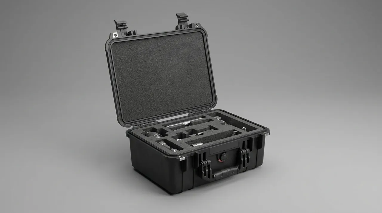
The chipping mechanism is physical. As the wheel rotates, the disc cutter rolls through the face and the edge cuts by line contact, taking one impact per tooth per revolution. That impact frequency follows wheel rotational speed, typically 5 to 12 rpm combined with 40 to 120 cutters. Every impact puts elastic and plastic strain on the very edge of the carbide, and because carbide is brittle the first defect to appear is a micro chip at the edge corner: surface flaws and residual stress extend along grain boundaries under impact loading. Once that chip exists, all subsequent stress concentrates at its root, and within several hundred to several thousand impacts the chip grows into complete tooth loss. The broken fragment enters the muck stream and immediately damages scraper edges and the main bearing raceway, so the cost of one chipped tooth far exceeds the cost of the cutter.
Cutter life is expressed as excavated volume in cubic metres, not as hours. One cutter may chew several hundred cubic metres of mudstone with low quartz content, or only a few tens of cubic metres of hard quartzite. Beyond rock type, cutter diameter, edge profile such as arc or conical edge, mounting inclination and wheel speed all affect life. At low wheel speed the disc slips across the rock face, edge temperature rises, and thermal fatigue combines with abrasive wear.
The transport contribution to this is regularly underestimated. A packaging failure does not show up as a broken case; it shows up as dust and moisture reaching the edge and producing a micro chip that fails within the first hour of operation. Cutter case liner, sealing and humidity class therefore sit at a higher level than wheel packaging. Cutters cannot simply be loaded into whatever timber crate the wheel segments happen to use.
Weld Deformation Stress Concentration at Cutter Seats
Cutter seats are joined to spokes and ring plates by gas-shielded arc welding, normally MAG or GMAW. Welding brings two problems: local stress rise from heat input, and overall geometric change. The seat is a stiff restraint point, and the plate on either side of the weld shrinks unevenly through heating and cooling, building stress concentration at the weld toe. A continuous weld across a long run can also bow the whole plate out of plane.
Out of the shop these distortions are easy to miss, because inspection measures flatness and hole spacing, while the decisive defect is the relation between the seat bore axis and the wheel axis of rotation. A skewed seat bore turns the disc cutter into a cutter chewing at an angle: the edge loads unevenly, local contact stress rises severalfold, chipping accelerates, and the extra torque feeds into the main drive gear and main bearing, accelerating pitting and raceway spalling. The datum relationship is only fixed once the wheel is mounted on the spindle flange, which is why cutter removal and installation sequence affects mounted precision.
Three routine control paths exist. Post-weld annealing or ageing removes residual stress, particularly in thick high-strength plate zones. Post-weld machining squares the cutter mounting face so all seats are coplanar and the flange-to-ring perpendicularity meets the manufacturer tolerance. After mounting, a wheel balance and skew check compares the resistance of every disc cutter by manual barring or low-speed rotation.
The packing responsibility here is unambiguous: transport shock must not cancel out the correction. Seat zones are not stacking supports and not lifting points. Wheel face up transport needs a uniform bearing surface rather than point contacts. Upright transport needs a dedicated cradle that restrains lateral displacement across the seat zone. With those three in place, weld and cutter alignment survive the road.
Leak Paths of Multi-Lip Main Bearing Seals
A shield main bearing normally combines double-row thrust ball bearings with a tilting roller or cylindrical element, carrying thrust of several thousand tonnes and transmitting torque in the thousands of kN·m. Its sealing is not a single lip. It is a multi-lip contact seal working with labyrinth rings and a pressure-relief cavity, so the lips both block slurry ingress and block grease egress from the gear case.
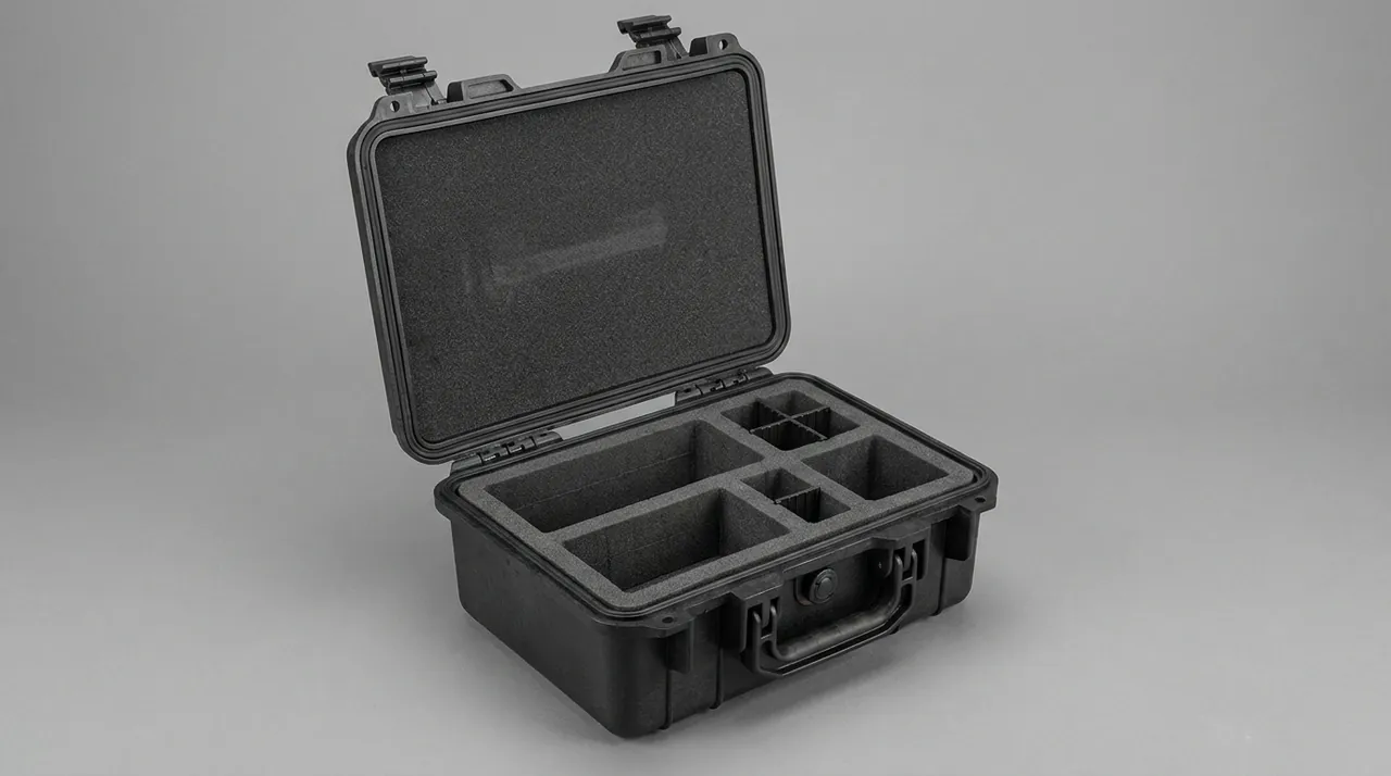
There are four leak paths. The first is contact band wear. The lips form a very narrow contact line against the journal or sleeve, and any hard particle mixed into the operating oil cuts grooves in that band. Sealing pressure then concentrates on the groove shoulders, and once the lip is scored the leakage jumps from seeping to throwing. The second is lip pressure imbalance. A multi-lip seal depends on spring or cage radial force to hug the journal; excessive squeeze raises lip temperature and accelerates hardening, while insufficient squeeze leaks directly as pressure fluctuates. The third is breathing pressure. Cyclic temperature in the gear case produces pressure breathing, pushing oil out when internal pressure exceeds ambient and drawing slurry in when it drops, which is what the relief cavity and breather exist for. The fourth is journal surface condition: rust, coating flaking, or residual corrosion inhibitor being carried away by abrasive particles will destroy the lip contact face within hours.
All four paths point at one precondition: transport protection must keep the sealing system uncontaminated, uncorroded and undamaged. In practice the seals themselves do not travel inside the bearing chamber over long distances. They are removed, sealed in their own pouches with model and installation direction marked, and shipped in a separate case. Rubber and nylon age and are attacked by vapours during months of storage, so separated storage preserves them better than leaving them installed. The bearing itself relies on a combination of body encapsulation, a corrosion inhibitor carrier, desiccant and a humidity indicator card, as described in Bearing & Gearbox Cases: Precision Fit Surface & Grease Protection.
Coaxiality is the second keyword. Main bearing installation checks coaxiality between the housing bore and the spindle flange, and the fit precision between the bore and the seal cavity. If transport gives the outer ring one lateral impact and produces slight plastic deformation, assembly may produce a loose outer ring to housing fit or a tilted bearing in its cavity. The first destroys the coaxial condition the multi-lip seal depends on; the second directly skews raceway loading. The logic matches Rolling Mill & Roll Cases: Roll & Chock Component Protection: fit surfaces come before appearance.
Gear Tooth Surface Pitting and Ring Gear Impact Protection
The main drive gear or ring gear is the far end of the shield torque path, usually connected to the main bearing outer ring or through an intermediate gearbox. Diameters run 2.5 to 4.5 m, module 30 to 60 mm, case-carburised and quenched flanks at 58 to 62 HRC, face width 300 to 600 mm, and single-piece weight from 20 to 60 t.
Three flank failure modes relate to transport protection. The first is pitting. Once contact stress exceeds the fatigue limit of the surface layer, pits appear and spread into spalling, and poor installation coaxiality or a residual bump on the flank worsens the stress distribution. The second is scuffing and fretting. Once the oil film is contaminated with dust, the flanks contact directly under high load, adhesive wear transfers material and builds a ridge, which then becomes a fatigue crack. The third is impact damage, the one that transport can directly cause and whose consequences are severe: a single 2 mm deep flank impact creates stress concentration at the tooth root and eventually produces root fatigue fracture, frequently on a loading cycle that is not the maximum one.
Ring gear packing therefore has specific requirements. It travels in its own case and never shares a case with wheel segments or the main bearing, because two items whose weights differ by an order of magnitude cannot share one cushion specification. Flank surfaces receive a long-term corrosion inhibitor or vapour corrosion inhibitor wrap to prevent pitting in a humid box. A rigid separator must sit between the flange and the flank so that the gear cannot tip onto the case wall in transit. Transport attitude is chosen so the flank takes no point load, normally a vertical cradle or a horizontal curved cradle loading the web rather than the tooth tips.
Handling of other large gear case pieces is covered in Pressure Vessel Component Cases: Head & Flange Component Protection, and the concentricity demands of large rings resemble those described for Drilling Rig & Tool Cases: Drill-Pipe Joint & Mud-Pump Protection. The common thread is fit surfaces first, weight second.
Cutter Wheel Jamming Under Slurry Pressure Balance
Face stability in a shield machine is achieved by one of two balance concepts. Earth pressure balance machines build pressure in the chamber through the thrust cylinders so the muck balances water and earth pressure at the face. Slurry balance machines inject slurry to form a filter cake and let the slurry pressure do the balancing. Neither allows the wheel to spin freely, because cutter speed and penetration rate must match or a slurry ring and cake form ahead of the face.
Cutter head jamming follows. Four common triggers exist: apertures clogging with a mixture of rock fragments and slurry so the cutting area collapses; slurry dewatering ahead of the wheel into a hard shell; the central soil column hardening during a long stop and being re-cut by the wheel edge; and large boulders or old piles being caught by the edge. Torque then climbs rapidly from the design band, typically 1500 to 4000 kN·m, toward jam levels at two to three times design, and the main drive gear and main bearing take sharply rising load.
Modern machines stop on a linked logic. Torque, rotational speed, penetration rate and slurry pressure are interlocked; when any one goes out of limit the machine stops advancing, increases reverse torque and keeps the wheel turning to break the jam. That logic protects the machine, but the inspection workload afterwards is heavy. Once the jam clears, the wheel carries numerous chipped cutters, squeezed and deformed seats, fresh scratches on the flank from hard rock, and cutters caked in slurry that must be cleaned one by one after chamber entry.
Packing for this batch of post-jam parts follows different logic from new parts. New parts are packed for precision protection; post-jam parts are packed for contamination isolation and secondary damage prevention. Wash first, dry fully, bag individually, then load into a disposable liner so slurry and moisture never reach precision neighbours.
Rock Abrasiveness Zones and Disc Cutter Life Consumption
The largest variable in disc cutter life is not hardness but rock abrasiveness. Engineers usually evaluate this with the Ceratec Abrasion Index from the Ceratec test. Rock with an index below 1 hardly wears cutters; 1 to 3 is moderate; 3 to 5 is significant; and material above 5, meaning high quartzite and chert, is extremely abrasive and can deliver less than a third of the life obtained in soft ground. Quartz content dominates, because quartz has a hardness of 7 and cleaves brittlely, so free grains plough the edge with a hard asperity; feldspar and mica follow, and calcite has low hardness but still contributes.
The effect on life is not linear. Hard rock does not only wear cutters faster, it raises line contact force and impact frequency, which speeds up carbide fatigue damage. The two contributions stack, producing the familiar pattern of consuming cutters quickly through sandstone and saving them through mudstone. That is why penetration rate and cutter consumption curves differ in slope between those formations on the same machine.
The design answer is zoned cutter selection: a high-toughness grade such as YG8 in soft ground, a harder grade such as YG15 in hard rock, with cutter diameter and mounting inclination adjusted to suit. The maintenance answer is replacement by excavated volume rather than by hours. Both rules apply equally to cutter transport, packing and turnaround. Cutters of different sizes and grades must never be co-loaded in one case; they are packed separately by seat number and grade, because the most common field error at replacement time is grabbing the wrong box.
The secondary path through packaging is equally clear. Fine rock dust is an abrasive. One seal failure that admits dust into a cutter case produces abrasive wear at the edge within the next start-up. This is the direct reason cutter cases are independently sealed and independently dried. Wear part management principles are shared with Cement Plant Parts Cases: Protection for Wear Parts & Inspection Instruments.
Moisture Management in Seepage and Slurry Conditions
Underground relative humidity stays high for long periods. Tunnel seepage, groundwater entering through segment and lining joints, and vapour carried by the slurry circuit combine to hold cutter components at 85% to 98% RH. For steel this is not damp but a persistent electrolyte: a film of water forms on the surface, chloride and sulphate concentrate in it, and corrosion starts at weld toes, edges and water collection points before developing into corrosion fatigue.
On the wheel the corrosion origin is usually the weld seam and the interface of hard alloy inserts. Carbide itself resists corrosion, but the fitted interface between alloy and steel base is prone to crevice corrosion in damp slurry, and once that interface loosens the insert can be thrown out in service. Between disc cutter alloy and ring, the fit is interference or adhesive, and corrosion products expanding at the interface push the original interference loose.
For the main bearing, high humidity is the primary threat to the seal system. Lip materials absorb moisture and soften in high humidity, so compression set accelerates. If condensation forms between a metal shield and the seal cavity it runs down the journal onto the lip contact face, which amounts to putting abrasive material on the lip.
Transport moisture management needs three components working together. Desiccant is dosed from cavity volume and expected storage duration so relative humidity stays acceptable through the longest waiting period. A humidity indicator card sits in a visible position and is read before opening, so an out-of-limit reading starts an internal drying step rather than an immediate scrap judgement. Structural ventilation means the liner leaves no closed dead cavity, so vapour is captured by the desiccant instead of lingering in one corner. Seals and small precision parts add a second level of isolation in their own sealed pouches. Moisture control for other long-term underground equipment is addressed in Metro Tunnel Fan Cases: Fan & Silencer Component Protection.
On weight and cost, desiccant volume on large steel segments is significant. A 20 t steel case stored 60 days needs several kilograms to more than ten kilograms of desiccant, which directly affects the payload budget and over-limit risk. That is why large cases often use a main box that is not fully sealed with a breathable internal layer. Condensation from temperature cycling is worst on sea routes.
Segmented Packing Scheme for Oversize Cutter Wheels
Any wheel above 8 m diameter must be shipped in segments. Road limits, typically 2.4 to 2.5 m clear width and 4.2 to 4.5 m clear height in a standard truck body, force one principle: arc segments can neither lie flat nor ride upright without purpose-built support. Ring plates are usually divided into 4 to 8 arcs of 45 to 90 degrees each, with segment weight held between 8 and 25 t so that flatbed picking in the works and truck loading on site both work.
Arc segments are the difficult object. Their stiffness is very low; two thin curved panels can deform under self-weight because the stress distribution is uneven, and road vibration and braking inertia amplify displacement further. If chord height changes, the assembled aperture ratio and cutter mounting angle change too, and aperture ratio is a process parameter that cannot be adjusted casually on site.
Four design rules follow. First, a dedicated curved cradle whose face matches the outer arc, using replaceable soft lining of 12 to 20 mm instead of hard contact, locates the part without crushing it. Second, transverse reinforcement beams on the arc back raise the bending stiffness of each segment by an order of magnitude. Third, ballast and centre-of-gravity marking, because an upright arc has a high centre of gravity, so the case must be marked with the centre of gravity height and a do-not-roll symbol, and lifting uses a two-point sling. Fourth, independent numbering against an assembly table, with packing order identical to installation order so the last segment always fits.
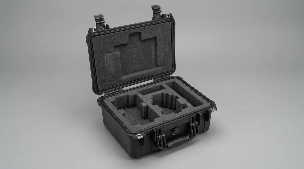
Table: three recurring site problems with segment schemes and their countermeasures
| Site problem | Root cause | Packing countermeasure |
|---|---|---|
| --- | --- | --- |
| Chord height out of tolerance on arrival | No transverse stiffening, vibration accumulated | Transverse arc-back beams plus a conforming cradle |
| Uneven aperture after assembly | Split boundary landed in a dense cutter zone | Move the boundary into a sparse cutter band before fabrication |
| Pre-assembly set will not close | Numbering inconsistent with the assembly drawing | Mark the identifier on both the steel and the crate |
| Seat bore axes skewed | No uniform bearing under the plate face | Face-up transport, uniform bearing face, no stacking |
Shell materials for large steel fabrications include steel-wood composite, aluminium extrusion frame with panels, and bolted polyethylene sheet. In heavy haul the case itself rarely fails by being struck; the internal support fails first and lets the load shift. Acceptance should therefore concentrate on internal restraint fixing and displacement records rather than shell appearance. Load calculations follow Heavy Duty Cases: High-Load Shell Structure & Handling.
Individual Disc Cutter Cases and Position Count Traceability
Disc cutters are the most numerous, most expensive and most easily miscounted components on the wheel. A shield of 8 m diameter may carry 60 to 90 disc cutters, and a major overhaul can involve well over a hundred tools including scrapers and gauge cutters. If these small items are mixed in a general toolbox, a shortage of one cutter on opening cannot be proven as transit loss rather than leftover from dismantling.
Disc cutter case design rests on cell location plus one-to-one correspondence. Each cutter occupies an individual cell, with the cutter body and carbide ring stored separately so the ring never contacts the body directly, and flexible filler between cells. A tool list card is fixed to one side of the case giving position number, cutter specification including diameter and edge type, carbide grade and quantity. Case labels correspond one-to-one with the position table, so any single cutter can be traced to its seat on the wheel in seconds.
Grade segregation is a separate discipline. YG8 and YG15 cutters never share a cell, because the harder grade edge is more easily chipped during storage and that defect goes straight to the wheel as lost life. Different diameters likewise do not share a cell, since differing edge and core curvature means stacking pressure damages the edges.
The case itself is built to small precision part standards. Lining is cell foam or replaceable EVA blocks, and lid lining must never press directly on cutter edges. Sealing class suits long sea routes, with desiccant and a humidity indicator card inside. Latch count follows case size and weight so a single point does not lever the lid open. Weight distribution matters as much as total mass: layouts are balanced left to right so the case does not lean and lose stackability.
These cases also serve as a record carrier. Alongside the parts they hold installation angle records, torque values and a post-installation check sheet. The field assumption that a cutter can go back into the same seat after a wheel change is often false, because layouts are re-zoned by rock type. With that sheet the number of removal and installation cycles becomes traceable.
Main Bearing Corrosion Encapsulation and Lifting Attitude
Main bearing transport follows one of two routes: assembled transport, or separated transport. Which one applies depends on whether the site can reassemble and adjust clearance.
Assembled transport suits cases that must not be opened and must be installed on arrival. Protection then focuses on preventing relative movement between inner ring, outer ring and cage during transit. A through-tie structure inside the case locks the three together without applying enough squeeze to damage the raceways. Lifting lugs are designed around that assembly's centre of gravity, and any support face must land outside the raceway zone.
Separated transport suits major overhaul work. Rings are packed individually, with vapour corrosion inhibitor film applied directly or a corrosion coating plus carrier. Seals, labyrinth rings and O-rings go into separate sealed pouches marked with model and installation direction. The cage is packed separately. No hard packaging material may touch a raceway surface; soft non-woven liner or corrosion-inhibiting paper is used instead. This route adds one indispensable step: clearance must be measured and recorded before dispatch, then re-measured on arrival and compared against the record. Deviation beyond the manufacturer's allowance means transit damage. For a main bearing this is the only reliable quantitative criterion; appearance cannot substitute for it.
Lifting attitude is the third factor. Main bearings weigh 20 to 80 t in most cases, and upright versus horizontal orientation changes the loading completely. Upright, the weight acts on the thin wall section and demands more ring stiffness. Horizontal, a support face landing near the raceway leaves a local impression in the raceway. The package must state permitted lifting points and permitted support faces, marked graphically on the case. Structural and lifting verification follows Heavy Duty Cases: High-Load Shell Structure & Handling.
One detail is often missed: main bearing cases carry desiccant but not arbitrary absorbents, because multi-lip seals and nylon cages can be sensitive to certain organic materials and absorbent type must be confirmed compatible with the seal materials. A humidity card and the clearance record sheet inside the case are low-cost field evidence.
Weld NDT and Disc Cutter Count: Receiving Acceptance Criteria
Receiving inspection limited to opening the case and looking for visible damage loses the two most valuable categories of evidence: internal weld quality on the wheel, and cutter count and edge condition. Both must be documented before dismantling.
Weld non-destructive testing. Before dispatch, welds joining ring plates and spokes should receive full visual inspection plus 20% to 30% magnetic particle or ultrasonic sampling, with records retained. Site assembly welds are tested on site to the design requirement. Three specific lines matter. First, the weld toe at cutter seats, which is both a stress concentration and a corrosion initiation point. Second, mismatched edge and root gap on segment butt welds, which determines whether site alignment can succeed. Third, interlayer defects in repair welded areas. NDT method selection for heavy welds follows the traceability practice described in Welding & Cutting Equipment Cases: Welder, Torch & Gas-Accessory Protection.
Disc cutter count. Reconciliation must be three-way: physical parts against the case list card, the card against the position table, and the position table against the wheel assembly drawing. Any mismatch enters the discrepancy process rather than being absorbed verbally on site. The correct method closes each box against the next and records expected quantity, received quantity, difference and difference reason, with the reason classified as transit damage, wrong case, or dismantling residue, since the three lead to completely different corrective actions.
Edge condition. Each cutter is inspected under strong side lighting for micro chips, backlash and edge curling. The insert-to-ring interface is checked by liquid penetrant or tap-tone for looseness. Ring rotation and clearance are spot-checked. Results are photographed and compared against the factory inspection photographs. The value of this step is that a micro chip absent at the factory and present on arrival attributes cleanly to packaging transport.
Main bearing acceptance. Read the humidity card before anything else, then re-measure clearance against the factory record, then confirm seal model and quantity are complete and free of aged deformation, then inspect raceways for rust transfer and indentation. The order cannot be reversed, because opening first and reading the card afterwards discards the humidity evidence.
Geometry and appearance. Segment chord height, spoke straightness and plate flatness are measured against factory records. The large ring gear is checked for flank impact damage and rust pitting, with hardness spot checks. Seat welds are inspected for appearance and bore position. Measurement records should include a point map so any later dispute can be reproduced.
Table: summary of receiving acceptance criteria
| Part | Criterion | Record |
|---|---|---|
| --- | --- | --- |
| Wheel segments | Chord height, straightness and flatness within factory deviation | Point map plus measured values |
| Seat welds | On-site NDT free of reportable indications | NDT report plus photographs |
| Disc cutters | Three-way count consistent, no micro chips, inserts tight | Reconciliation sheet plus side-light photographs |
| Main bearing | Re-measured clearance within allowance, seals complete | Clearance record sheet |
| Ring gear | No flank impact, no rust pitting | Flank photographs plus hardness spot check |
| All cases | Humidity card reading within limit | Reading photograph |
Frequently Asked Questions FAQ
Q: Is a cutter wheel above 6 m diameter still realistic to ship as one piece?
A: Only below about 6 m, and only if upright height stays under 4.2 m and weight under 30 t. Even then the packaging volume is enormous, the vehicle must be a low-bed heavy trailer, and oversize permits are needed for parts of the route. Above that range disassembly is the only option, and the judgement runs in a fixed order. First, measure whether the overall envelope fits road and trailer limits. Second, check whether whole-piece lifting and vehicle axle loads stay within structural capacity. Third, estimate whether the crate's own weight pushes the total into an oversize band. If any one of the three fails, move to a block plan. In practice almost everything above 8 m gets blocked, and it is rarely the envelope test that fails first; more often it is the axle load once crate weight is added. Segment weight is then held between 8 and 25 t per piece.
Q: Why must disc cutters ship in their own cases rather than travelling with the wheel blocks?
A: Three separate requirements force the separation. First, precision class: a wheel is a multi-tonne steel structure where penetration resistance and stiffness govern, so its liner is a dense rigid layer, while a disc cutter has a carbide edge that fails under local contact pressure and vibratory abrasion, so it needs precisely located foam compartments. Those two requirements point in opposite directions on cushioning density and thickness. Second, unequal consequences: a scuffed wheel face can be ground and repaired on site, whereas a chipped cutter edge is scrap and takes scraper edges and main bearing raceways with it. Third, traceability: cutters are issued by position number, and mixing them destroys the one-to-one record. Cutters, scrapers and gauge cutters are therefore boxed separately by size and grade, each with its own manifest. That separation is also what lets a missing cutter be noticed at the depo rather than on the face, because the count is reconciled against the position table before the wheel is ever hung.
Q: A disc cutter arrives with a small chip on its carbide edge. Can it go back on the wheel?
A: It depends on chip depth and location. A micro-step at the edge corner, visible only as a contour change under raking strong light, is normally a transit contact mark that a field grinding pass can remove, but the record must be kept and the restored profile verified afterwards. If the chip has become a visible notch, if the contour line is interrupted, or if a gap has opened at the insert-to-ring interface, the damage is not acceptable and the cutter should be scrapped. Three questions decide it: does the defect sit inside the load-bearing band of the edge, does its depth exceed what grinding can remove, and has the interface already loosened? When those answers do not point to reuse, changing the cutter is the correct action rather than continuing with it. A record of the decision protects both parties if the edge later fails in service. The inspection threshold is deliberately conservative, because a cutter that fails at the face takes scraper edges and the main bearing raceway with it, and that cascade is far more expensive than one spare cutter.
Q: Must the main bearing travel in the assembled condition?
A: No; it depends on whether the site can reassemble and adjust clearance. Assembled transport means the bearing installs straight away, but the crate volume is large, an internal restraint is needed to lock inner ring, outer ring and cage together, and any relative movement during transit causes damage that is effectively irreversible. Separated transport needs a clean assembly area and the ability to measure clearance, and its advantages are graded packaging of individual rings plus separate control of seals and corrosion protection. Most overhaul projects choose separated shipping, and two companion actions are then mandatory: measure and record clearance before dispatch, then re-measure on arrival for comparison. That record is the one quantitative criterion for a main bearing that visual inspection cannot replace. It also lets the overhaul team decide on the spot whether the bearing can be reused, rather than discovering a clearance shift only after the wheel is already hung and the shaft is in place.
Q: How is humidity controlled for wheel packaging in a seepage-prone tunnel environment?
A: Three mechanisms work together: desiccant, humidity indicator cards and structural venting. Desiccant is dosed from cavity volume and the longest expected storage period so relative humidity stays inside an acceptable band across the full waiting period. The indicator card goes where it can be read before the lid comes off; read it first, and if the reading is out of limit, dry the interior before deciding whether parts are damp, rather than treating a colour change on the card as automatic evidence of scrap. Structurally, the liner must leave no sealed dead cavity so vapour is captured by the desiccant instead of lingering in a corner. Large steel parts add a weight problem: a 20 t component in 60-day storage can need several kilograms of desiccant, and that mass must be counted in the payload budget before the route is booked. Skipping that step is the usual reason a sealed crate arrives with a saturated card, because the desiccant runs out while the part is still waiting underground.
Q: Should multi-lip seals be replaced the moment the main bearing crate is opened?
A: Not automatically; it depends on transit time and storage conditions rather than a blanket replacement rule. Seals that have been out of working condition, bagged, and kept in a dry environment for less than a few months will usually still be serviceable after visual and dimensional checks. Seals that have seen a long sea voyage, wide temperature and humidity cycling, or that show hardening, crazing or permanent set should be replaced. Examine the lip land for retained flexibility, look for fine longitudinal cracks, and confirm the sealing print against the shaft neck is clearly defined. When fitting, use the same model and material as specified and set compression to the manufacturer figure rather than adding pressure by feel, because over-compression is the primary route to accelerated lip hardening in service. The same caution applies to storage position, since a seal left folded under weight takes a set that no amount of warm-up will remove before installation.
Q: How should damaged parts stripped after a cutter head jam be packed for transport?
A: Treat them for contamination isolation and secondary damage protection, which is the opposite of the new-part approach. Step one is washing and drying: remove all rock dust, slurry and oil with water or a neutral cleaner, then blow or oven dry, because slurry held inside a crate keeps chlorides and sulphides attacking steel. Step two is individual bagging, so corroded items, chipped cutters and slurry-cemented tools go into separate sealed bags and nothing contaminates precision parts nearby. Step three is secondary damage control, giving deformed seats and bent scrapers individual soft supports instead of locating them by stacking against each other. Mark the consignment as fault parts, attach the jam condition record and the removal list inside the case, and keep the batch traceable for later failure analysis. Treatment as fault parts rather than scrap also preserves the evidence the maker needs, because a stripped head often reveals the root cause that decides the next cutter specification.
Q: What must be checked separately for disc cutters and for the wheel on arrival?
A: The two have completely different logic. For cutters, check count and edges. Reconcile box by box three ways: physical against the case list card, card against the position table, position table against the assembly drawing, and classify any difference as transit damage, wrong case or dismantling residue. Then inspect every edge under strong side lighting for contour breaks, and use liquid penetrant or tap-tone to confirm the insert interface is tight. For the wheel, check geometry and welds: measure segment chord height, spoke straightness and plate flatness against factory records, run on-site NDT on seat welds and segment butt welds, and concentrate on weld toes and mismatched edge. The opening sequence also matters, because reading the humidity card after removing wheel restraints, or counting cutters after stripping liners, destroys the evidence.
Conclusion and Related Reading
Cutter wheel transport fails by distortion, disc cutters fail by edge chipping, main bearings fail by seal and rust damage, and each needs its own case logic. Fixing split boundaries, cushioning direction and acceptance criteria before dispatch cuts cost more effectively than a thicker shell. JUNZHIJIA supports segmented wheel schemes, custom disc cutter case tooling and main bearing corrosion encapsulation, with OEM/ODM and case documentation including list cards, clearance records, NDT reports and humidity cards.
Related Reading