

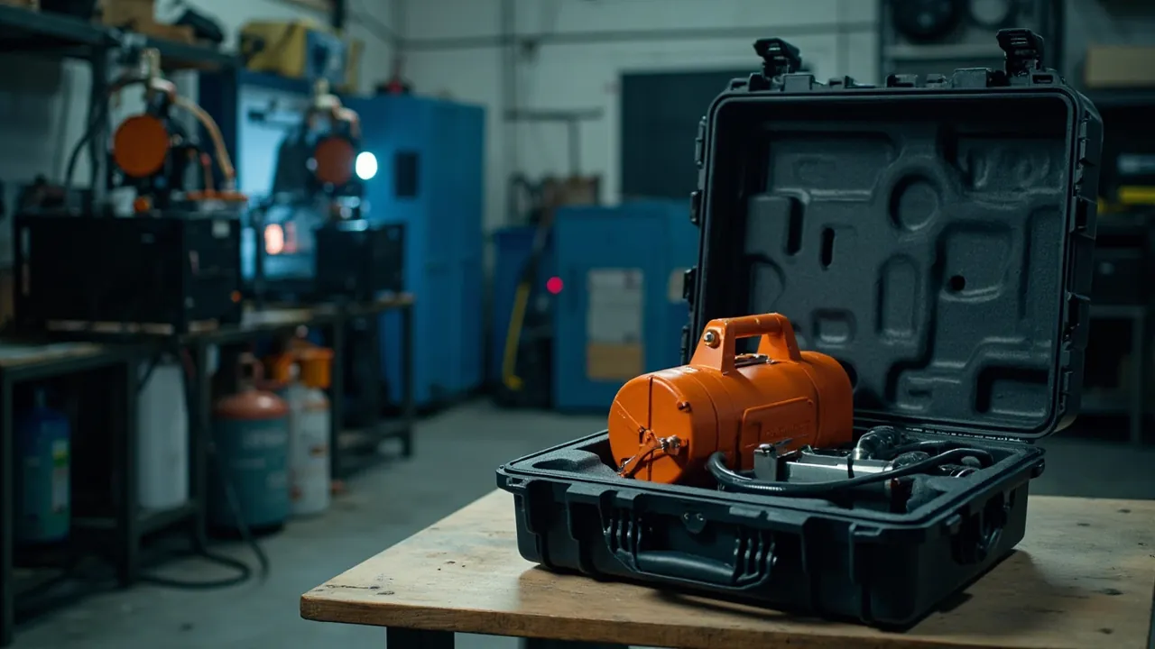
Protecting welding and cutting equipment in transit means getting three things right at the same time: moisture control, vibration control, and discipline over gas accessories. A welding power source is electrical equipment whose inverter modules, control boards and capacitors are sensitive to humidity, static and impact. A torch, gun or tungsten electrode is a precision hand tool that is also fragile. A regulator, flashback arrestor or hose is a pressure-rated accessory tied directly to gas safety, and damage to it affects not just weld quality but site safety. A welding equipment case therefore cannot be designed on a toolbox mindset. It must protect three entirely different classes of object, namely electrical components, precision tools and pressure-rated accessories, with a different approach for each. JUNZHJIA supplies machine-dimension-specific compartment inserts, cable-coiling modules, accessory fixing positions and OEM/ODM programmes for welding and cutting equipment.
One boundary must be stated clearly up front. This article deals with packaging protection for welders, torches, cables, regulators, hoses and similar equipment and accessories. A gas cylinder itself is a pressure vessel and a dangerous good, and its filling, storage and transport are governed by mandatory regulations covering gas cylinder safety, road, rail, sea and air carriage of dangerous goods. No compliance conclusion is offered here, and an ordinary equipment case must not be treated as a substitute for a compliant cylinder transport arrangement. The proper role of an equipment case is to manage accessories, tools and consumables so that the cylinder body can be transported separately, upright and reliably within the applicable compliance framework.
Welding also has a distinctive operating pattern: field service and mobile fabrication. Welders and accessories routinely travel with crews, loaded onto trucks, pickups and service vehicles, and sometimes into petrochemical plants, vessel compartments and high-rise construction sites. That route, involving multiple legs, repeated loading and unloading and open-air work, is far more demanding than in-plant handling. This article is written for equipment management, safety and procurement staff at welding equipment manufacturers, welding consumable and accessory suppliers, and engineering and maintenance service companies. Figures quoted are typical industry values or empirical ranges; the governing inputs are the product technical documentation, mandatory safety regulations and the customer's acceptance specification.
Table of Contents
- 1. Risk Profile for Welding and Cutting Equipment in Transit
- 2. Welder, Torch and Gas Accessories: Critical Parts and Failure Modes
- 3. Welder Cases: Enclosure, Inverter Module and Control Board Protection
- 4. Wire Feeders, Guns and Torches: Cables, Hoses and Nozzle Protection
- 5. Gas Accessories and Regulators: Flashback Arrestors, Hoses and Anti-Tip Control
- 6. The Regulatory Context of Cylinder Handling and the Compliance Boundary for Equipment Cases
- 7. Welding Cables and Quick Connectors: Bend Radius and Terminal Protection
- 8. Consumables: Moisture Management for Electrodes, Wire and Tungsten
- 9. Component-to-Case Selection Matrix
- 10. Insert and Moisture-Control Materials Compared
- 11. Sealing, Moisture Control and IP Ratings: IEC 60529 and GB/T 4208
- 12. Transport Test Basis and Standard Packing Workflow
- 13. Sea Export, Field-Service Cases and OEM/ODM Customisation
- Frequently Asked Questions
- Conclusion and Further Reading
1. Risk Profile for Welding and Cutting Equipment in Transit
To understand transport protection for welding and cutting equipment, first sort it into three groups with completely different natures.
The first group is electrical equipment: the power source itself. Whether inverter-based, rectifier-based or transformer-based, a welding machine is fundamentally electrical equipment with power electronics and control. An inverter welder contains IGBT power modules, rectifier bridges, electrolytic capacitors, a high-frequency transformer and control boards, all of them precision electrical assemblies. A transformer welder is simpler and sturdier, but heavy, typically 30 to 200 kilograms or more, so the dominant transit risks shift to enclosure deformation, loosening of internal wiring and fasteners, and moisture ingress into insulation. The arc welding equipment safety standard, IEC 60974-1, with the equivalent Chinese standard GB/T 15579.1, specifies enclosure ratings, environmental conditions and mechanical strength for welding power sources. Enclosure ratings are commonly expressed as IP21S or IP23S, which use the general IEC 60529 framework with qualifications specific to arc welding duty.
The second group is precision hand tools: guns, torches and their parts. Guns and torches are defined by handling precision. Nozzle bore, contact tip bore, diffuser gas ports and the bore and concentricity of a cutting tip directly govern weld bead formation and cut quality. These features are small, thin-walled and easily deformed. Ceramic shields and nozzles are fragile, tungsten electrodes are slender and snap easily, and wire conduit liners are damaged by kinking and crushing. The failure signature for a hand tool is that it looks fine but does not work: a nozzle with a burr disturbs shielding gas flow, and a deformed contact tip bore sends wire off axis.
The third group is pressure-rated and safety accessories: regulators, flashback arrestors, hoses and cylinder valves. This group is tied directly to gas safety. A regulator contains a diaphragm, spring and valve seat and is a precision pressure assembly, so impact causes pressure-setting drift or leakage. A flashback arrestor is a safety device whose non-return and flame-arresting elements must not be contaminated or mechanically damaged. Hoses fear kinks, crushing and contact with oils and solvents. Protection for this group is not just a quality matter; it is a safety matter.
Four governing principles follow.
First, keep the three groups in separate zones. Electrical equipment fears moisture and static, tools fear impact and deformation, pressure accessories fear contamination and squeeze. Putting all three in one cavity guarantees failure on at least one dimension. The correct approach is three zones: the welder fixed independently, tools compartmentalised and upright, accessories fixed independently and capped.
Second, let structures carry weight, never functional faces. A welder's weight should pass through its feet or a dedicated load block. A torch tip or nozzle must not be a bearing surface in any direction, and a regulator's gauge or adjusting knob must not be loaded.
Third, moisture control is the first priority for welders. Humidity in welding shops and on site swings widely. Long storage or sea transit in humid conditions degrades insulation, corrodes power devices and damages control boards. The moisture requirement during transport and storage is often stricter than during normal service, because in service there is ventilation and self-heating to drive off moisture, whereas in transit the equipment sits in a closed, unheated case.
Fourth, consumable moisture control must be closed-loop. Low-hydrogen and basic electrodes that take on moisture must be re-dried to the specified schedule or they will produce porosity and hydrogen-induced cracking. Flux-cored and solid wire corrode and feed poorly after absorbing moisture. Tungsten electrodes fracture under impact. If consumables are mishandled, welding quality cannot be assured even when the equipment is perfect.
A common misconception treats a welding equipment case as a sturdier toolbox. A toolbox aims at stowage and carrying convenience. An equipment case aims at ensuring the equipment can be used, the accessories assembled and the pressure parts safely commissioned on arrival. The two are verified in entirely different ways.
2. Welder, Torch and Gas Accessories: Critical Parts and Failure Modes
| Object | Critical parts | Primary failure modes | Trigger | Priority countermeasure |
|---|---|---|---|---|
| --- | --- | --- | --- | --- |
| Inverter welder | IGBT modules, control board, electrolytic capacitors | Moisture corrosion, ESD damage, solder fatigue | High humidity, condensation, static, shock | Sealing plus desiccant plus low-rebound floating fixation |
| Transformer welder | Winding insulation, terminals, enclosure | Insulation moisture, loose terminals, enclosure deformation | High humidity, handling shock, stacking load | IP65 case plus foot load path plus restraint |
| Wire feeder | Drive rolls, conduit liner, motor | Roll damage, liner kink, motor vibration | Compression, kinking, vibration | Dedicated cavity plus soft pad plus no top load |
| MIG or TIG gun | Contact tip, nozzle, collet | Bore deformation, nozzle damage, electrode fracture | Mixed packing collisions, dropping, stacking | Upright compartments plus nozzle protectors |
| Plasma cutting torch | Tip, electrode, swirl ring | Tip bore deformation, concentricity loss | Hard-object impact, drop | Dedicated torch case plus clearance cavity |
| Ceramic shield | Ceramic body | Fracture, chipping | Impact, squeeze | Separate compartments plus soft separation |
| Tungsten electrode | Rod body, tapered tip | Fracture, tip chipping | Stacking, bending, impact | Rigid tube plus axial restraint |
| Regulator or flowmeter | Diaphragm, seat, pressure gauge | Setting drift, leakage, broken gauge | Drop, compression, dirt ingress | Dedicated box plus gauge guard plus port plugs |
| Flashback arrestor | Non-return and flame-arresting elements | Loss of function, internal contamination | Dirt ingress, mechanical damage | Port capping plus independent fixing |
| Cylinder valve and cap | Valve thread, stem, valve cap | Thread damage, stem deformation, cap loss | No restraint, horizontal rolling | Cap plus bumper ring plus upright restraint |
| Welding cable | Sheath, conductor, connector | Sheath cracking, strand breakage, connector deformation | Cold bending, over-flexing, dragging | Large-diameter coiling plus minimum bend radius |
| Quick connector | Pin, sealing face, locking sleeve | Sealing face scoring, sleeve deformation | Impact, sand and dust ingress | Protective caps plus separate compartments |
| Electrodes and wire | Flux coating, copper coating, spool form | Moisture uptake, flux loss, corrosion, spool loosening | High humidity, compression, poor stowage | Desiccant plus sealed bag plus spool locating |
These thirteen failure modes reduce to one sentence: electrical parts fear moisture and vibration, tools fear impact and deformation, pressure parts fear contamination and squeeze. The three classes need different design logic, which is precisely why a welding equipment case must be compartmentalised to order.
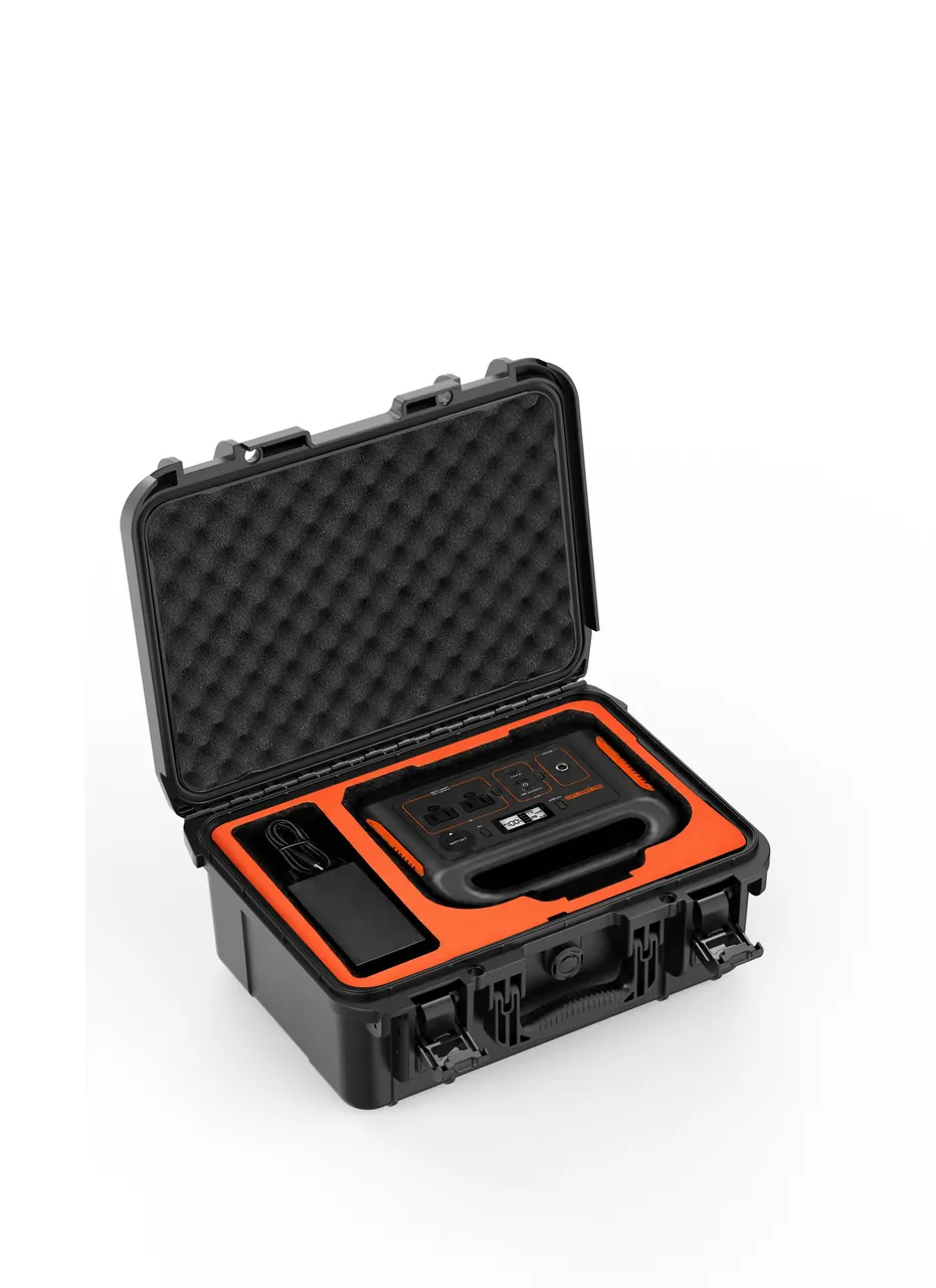
3. Welder Cases: Enclosure, Inverter Module and Control Board Protection
The welder is the main body in a welding equipment case and the heaviest and most valuable item.
What makes an inverter welder sensitive. An inverter welder obtains welding current by rectifying, inverting, transforming and rectifying again, and its core is power semiconductor modules, typically IGBTs or MOSFETs, together with a high-frequency transformer. Three protection points follow. The first is moisture: power modules and circuit boards corrode electrochemically in humid conditions, and saline sea-freight environments are especially unfavourable; during transport a welder has no self-heating to drive off moisture, so sealing and desiccant must do the work. The second is static: control and driver boards contain electrostatic-sensitive devices, and ESD damage is hidden and delayed, sometimes surfacing weeks after commissioning. The third is mechanical shock: heat sinks and solder joints on large power modules are shock-sensitive, and strong impact can cause solder fatigue. Inserts should therefore emphasise full floating cushioning in low-rebound material rather than hard clamping, because hard clamping passes shock straight into the module.
A different logic for transformer welders. Transformer and tapped welders are simple and robust and do not fear transport as such; the risk lies in weight and enclosure. A large machine may weigh over 100 kilograms, and a drop during handling lands directly on the base plate and case corners. Priorities are a case with lifting or fork capability, a foot or dedicated load block that carries the whole weight and spreads it into the case base structure, and restraint between enclosure and insert to prevent sliding and impact. Note also that long storage in high humidity degrades winding insulation, so moisture measures cannot be omitted.
What the enclosure rating actually covers. The arc welding equipment standard, IEC 60974-1 and its Chinese equivalent GB/T 15579.1, specifies enclosure ratings for welding power sources, commonly written as IP21S or IP23S, based on the general IEC 60529 and GB/T 4208 framework but qualified for arc welding duty. Note clearly that a welder's own enclosure rating addresses protection against solid objects and water during workshop service. It does not mean the machine can be placed in a sealed case for long-term storage in a sea-freight environment. The two are not equivalent. The sealing level of the transport case should be determined separately from the transport route; see choosing the IP rating of a waterproof case.
Protecting panels and interfaces. The adjustment knobs, digital display, remote interface and gas port are exposed features whose repair cost is not trivial. Face the panel inward or overlay it with soft material, protect knobs and connectors with caps or clearance cavities, and plug the gas port to keep dust and moisture out of the internal gas path.
Accessories and documents. Welders ship with remote controls, manuals, certificates, test reports and special tools. Keep these in a document wallet fixed to the inside of the lid so they cannot move and crush parts or go missing.
Lifting points. Mark lifting and forking positions explicitly, and prohibit the use of the welder's own handles, cables or gas hoses as lifting points. Misuse of lifting points is a common cause of transport accidents.
4. Wire Feeders, Guns and Torches: Cables, Hoses and Nozzle Protection
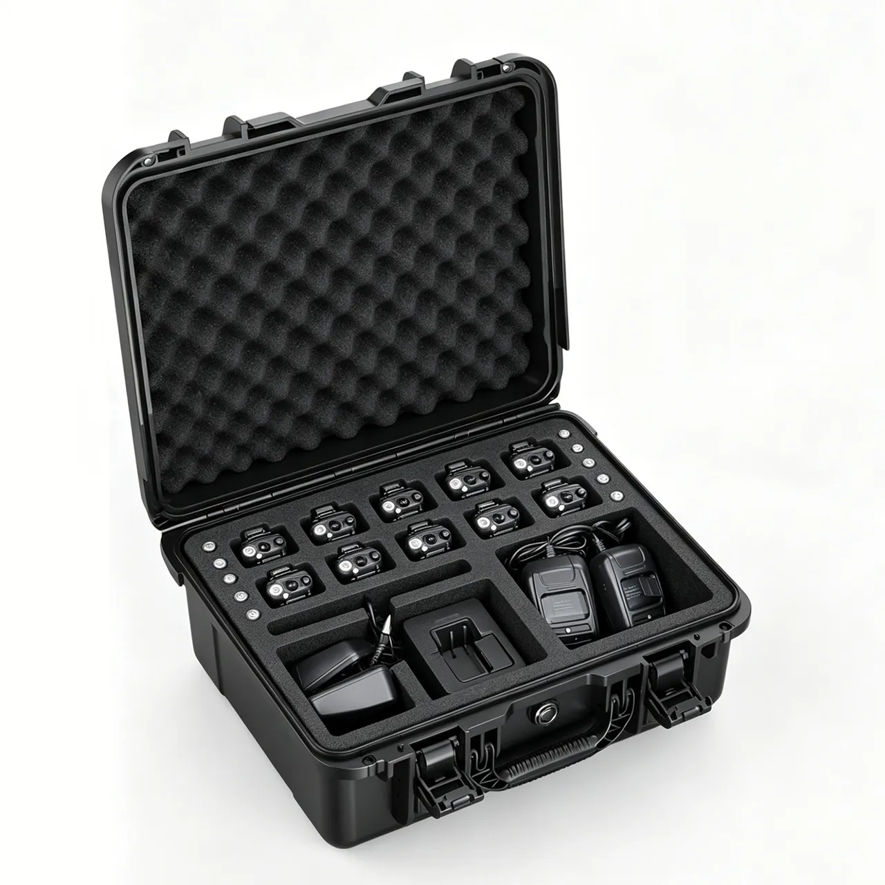
Guns, torches and wire feeders are precision hand tools, and their protection logic is entirely different from that of electrical equipment.
Where the functional precision of a gun or torch sits. The critical parts of a MIG or MAG gun are the contact tip, tip holder, diffuser and nozzle. For a TIG torch they are the collet, ceramic nozzle and gas lens. For a plasma cutting torch they are the electrode, tip and swirl ring. All share a common character: small bores, thin walls, high machining accuracy, and tolerances that directly affect gas flow and arc stability. A nozzle bore with a burr disturbs shielding gas flow and produces porosity and oxidation in the weld. A deformed contact tip bore drives wire off axis, causing spatter and undercut. A deformed or non-concentric cutting tip causes dross and a non-vertical cut face. The common signature is that the visible damage is slight while the functional loss is large.
How to pack guns and torches.
- Upright compartments. Give each gun or torch its own compartment, standing upright or in the designed posture with the nozzle end up or outward, touching no hard object.
- Nozzle protectors. Fit protectors over nozzles, contact tips and ceramic parts so they take no load at all. Ceramic shields must have separate compartments and soft separation.
- Clearance cavity. The head of a gun or torch is generally larger in diameter than the barrel, so design a clearance cavity to prevent the head from jamming and being squeezed during removal.
- No tight coiling. Never coil cables or wire conduit liners to a radius below the minimum. A liner that has been kinked keeps a permanently deformed inner wall and feeds wire erratically.
- Separate hoses and gas lines. Coil gas lines and liners separately and fix them so they cannot swing and tangle with other parts.
Protecting the wire feeder. Drive rolls, the pressure arm and the conduit liner are the feeder's precision parts. A damaged drive roll produces uneven feed marks, and a kinked liner raises feed resistance sharply. Fix the feeder in its own cavity on soft lining, never stack weight on top of it, and avoid leaving the liner in a bent posture for long periods.
Protecting tungsten electrodes. Tungsten electrodes are slender and brittle and break in transit more often than expected. Use a rigid tube such as a plastic or paper tube, one electrode or one bundle per tube, plug both ends, restrain axially so the electrodes cannot slide inside, and keep them away from metal parts that could score them. Note also that some tungsten types, such as thoriated grades, contain a small radioactive component; their labelling, storage and disposal should follow the applicable regulations and the supplier's instructions and they should not be discarded casually or mixed with metal scrap. Specific occupational health and environmental requirements follow local law and company policy.
Isolating anti-spatter spray and volatile consumables. Anti-spatter spray, cleaners and solvent-based consumables contain volatile constituents. In a closed case these volatiles form an organic atmosphere that can corrode electronics, soften rubber and create odour. Keep them in sealed packaging, out of the same cavity as electronics, and never in long-term storage inside a closed case.
5. Gas Accessories and Regulators: Flashback Arrestors, Hoses and Anti-Tip Control
Gas accessories are the most underestimated class in a welding equipment case and the most closely tied to safety.
The precision inside a regulator. A regulator contains a diaphragm, an adjusting spring, a valve seat and a valve stem, balancing forces to hold outlet pressure steady. This structure is sensitive to three things. Impact from a drop displaces the spring or bends the stem, showing up as unstable or unadjustable outlet pressure. Contamination from dust, metal swarf or oil entering the valve port prevents proper closure and causes leakage. Overpressure on the high side damages the diaphragm. A regulator must therefore never be loose in a case. Fix it independently, guard the gauge, cap the inlet and outlet, and keep the adjusting knob unloaded.
Two requirements deserve emphasis. Regulators for oxygen and for fuel gas must not be interchanged, and regulators must not contact grease or oil. This is fundamental gas safety practice and it applies at the packaging stage too: oxygen accessories must not touch oils, greases or any material that could introduce oil, including certain liners or lubricants. Confirm that insert and packaging materials do not bring oil contamination. Applicable requirements follow the gas supplier's instructions and the relevant safety regulations.
Flashback arrestors. A flashback arrestor sits in the gas line to stop a flame front travelling back through the system. It contains non-return and flame-arresting elements and is a safety device whose failure has serious consequences. Cap the inlet and outlet to keep out dust, never dismantle it, protect it from mechanical damage, and inspect or replace it at the intervals the supplier specifies. During packing and transport, separate it from metal parts so the internal elements are not shocked.
Hoses and quick connectors. Rubber hose is vulnerable to four things: kinks that permanently deform the inner wall, crushing that reduces flow area, oils and solvents that swell and age the rubber, and ultraviolet light and ozone that crack the surface. Quick connector pins and sealing faces are precision fits, and sand or dust ingress causes poor sealing and leaks. Coil hoses to no less than the specified minimum bend radius and fix them in place, fit protective caps to connectors, keep them away from oil-based consumables, and avoid prolonged exposure to sunlight.
The protection logic for cylinder valves and caps. The boundary must be clear: a gas cylinder itself is a pressure vessel whose transport is governed by mandatory regulations and falls outside the scope of an equipment case. However, an equipment case frequently needs to stow cylinder accessories such as the valve protection cap, the rubber bumper ring, a dedicated wrench and valve port plugs. These accessories matter because the cap and bumper ring are among the legally required protective elements for cylinder transport, and losing or damaging them directly affects compliance and safety. Give them dedicated positions so they are not lost.
Build an accessory checklist into the case. Gas safety on site depends on a complete set of accessories in good condition. Provide labelled positions inside the case for the regulator, flashback arrestor, hoses, connectors, wrench and leak-detection fluid, each in its own compartment. Check the list at unpacking and again before loading the vehicle. This costs very little and substantially reduces the risk of arriving on site with a missing flashback arrestor.
6. The Regulatory Context of Cylinder Handling and the Compliance Boundary for Equipment Cases
This section exists because the boundary is where welding equipment packaging most often goes wrong.
The legal character of a gas cylinder. A cylinder holding compressed, liquefied or dissolved gas is generally treated as a pressure vessel, and its filling, storage, transport, use and periodic inspection are governed by dedicated regulations and technical rules. In transport, most gases, including acetylene, oxygen, argon, carbon dioxide and propane, are classified as dangerous goods, and road, rail, sea and air carriage are each covered by their own rule sets:
- Road carriage within China: governed by dangerous goods road transport regulations and standards, with specific requirements for vehicles, markings, restraint and personnel qualification for cylinders;
- Road carriage in Europe: governed by ADR, the European Agreement concerning the International Carriage of Dangerous Goods by Road;
- Sea carriage: governed by the IMDG Code, the International Maritime Dangerous Goods Code;
- Air carriage: governed by the IATA Dangerous Goods Regulations and comparable frameworks.
Important boundary statement: these regulatory frameworks address the compliant transport of the cylinder itself and its contents. The welding and cutting equipment case discussed here is not a cylinder transport device and does not qualify as a substitute for a compliant cylinder transport arrangement. Loading and transporting a gas cylinder in an ordinary protective case is outside the scope of this article's recommendations. The correct role of the equipment case is to stow and protect the welder, torch, cables, regulator, hoses, tools and consumables.
Why this boundary matters in practice. Three errors recur. The first is laying cylinders horizontally in a toolbox or vehicle bed and relying on padding and strapping. The second is leaving the regulator permanently attached to the cylinder while the vehicle is in motion. The third is packing gas accessories loose with metal tools so that they are damaged and then still used. All three share a common pattern: seeking convenience outside the regulations and transferring the resulting safety risk onto the people working on site. A clear sense of that boundary is itself part of good protection design.
What an equipment case can legitimately do within a compliant framework. Assuming the cylinder itself is transported per the regulations, an equipment case performs four useful functions. It stows and protects the regulator, flashback arrestor, hoses and connectors so they are neither damaged nor contaminated in transit. It stows cylinder protective accessories such as caps, bumper rings and dedicated wrenches so their loss does not compromise cylinder transport compliance. It stows leak-detection fluid and gas-detection items for safety checks. And it separates tools, consumables and accessories into zones so the pre-departure checklist can be run quickly. For general expectations around dangerous goods packaging and transport see ADR and IMDG hazmat transport case points.
An extra reminder for field service. Welding and cutting equipment frequently enters petrochemical plants, tank farms and vessel compartments where explosive gas atmospheres may exist. Note clearly that electrical equipment and tools used in an explosive atmosphere must meet the explosion-protection requirements of that location, and an equipment case cannot confer suitability on non-explosion-protected equipment. Procurement and use should follow the owner's hot work permit, gas detection and hazardous area classification rules. What an equipment case can do is keep equipment in sound condition during transport and storage, reducing site risk that originates from equipment defects.
7. Welding Cables and Quick Connectors: Bend Radius and Terminal Protection
Welding cable is the part of a welding set most easily damaged and most often overlooked.
How cable fails. Welding cable comprises a stranded copper conductor and a rubber or elastomer sheath. Failure is rarely a single break; it is progressive degradation. Once the sheath cracks, moisture and dust enter and the conductor oxidises. Repeated flexing breaks individual strands, reducing effective cross-section so that heating increases at high current. Terminals loosen and oxidise under repeated load, raising contact resistance and generating heat. These processes accelerate under high temperature, high humidity and saline conditions.
Cold brittleness. Rubber sheaths harden and embrittle at low temperature, and forced bending then cracks them. This matters in northern winters and in cold destinations during winter export. In cold conditions, avoid sharp bends and dragging when handling and uncoiling cable, and where necessary allow it to return to room temperature first. The minimum service temperature follows the cable's technical data.
Minimum bend radius. Cables and hoses have specified minimum bend radii. Coiling below that radius puts the inner sheath in tension and the outer in compression, and long storage leaves permanent deformation. The coiling module in a welding case should therefore be designed around a coil diameter no smaller than the minimum bend radius, and the coil should be tied after winding so it cannot loosen and tangle. Requirements for welding cable and rubber-sheathed flexible cable are covered by standards such as the IEC 60245 family.
Protecting quick connectors. Welding cable quick connectors carry high current through a pin and spring contacts whose surface accuracy and spring pressure determine contact resistance. Impact deforms the pin or loosens the locking sleeve, producing poor contact and heating. Fit protective caps, isolate each connector in its own compartment so it cannot strike metal, and keep it clean and dry so sand and oil cannot enter.
Ground cable and work clamp. The ground cable and work clamp are part of the current path. The jaws and spring of a clamp deform easily under impact, leading to poor grip and poor contact. Fix the clamp independently so its jaws take no load.
Why cable management pays. How cables and hoses are stowed inside the case determines how quickly they can be deployed on site. Use one coil per length, group by purpose, standardise the coil diameter, and label each coil with purpose and length. For compartment and coiling structures see removable divider system concept.
8. Consumables: Moisture Management for Electrodes, Wire and Tungsten
Consumable management is a distinct and critical part of a welding quality system, and its packaging requirements are often stricter than those of the equipment itself.
Consequences of electrode moisture uptake. The coating of low-hydrogen and basic electrodes contains moisture and hygroscopic constituents. If a damp electrode is not re-dried to the specified schedule, moisture dissociates during welding and hydrogen enters the weld pool, potentially causing porosity and hydrogen-induced delayed cracking. The defining feature of hydrogen cracking is that it does not appear immediately after welding; it may show up hours to days later, which makes it a serious risk for pressure-containing and dynamically loaded structures. Storage and transport of electrodes must therefore control humidity, packaging must be sealed, and after opening, storage and re-drying should follow the company's welding procedure documentation. Specific drying temperatures and times follow the electrode type data sheet and the qualified welding procedure.
Flux-cored and solid wire. Flux-cored wire contains flux powder that also absorbs moisture, producing porosity and unstable arc behaviour. Copper-coated solid wire corrodes after moisture uptake, and copper loss clogs contact tips and impairs feeding. The most common transit problem for spooled wire is spool loosening: once the winding loosens, strands tangle and cannot be fed. Secure the spool form with straps or film, provide a spool spindle or locating recess in the case so the spool cannot roll, and control humidity with sealed bags and desiccant.
Electrode holding ovens and field storage. A portable electrode oven is the intermediate link between the drying oven and the work point, and its sealing and insulation performance directly governs how fast electrodes reabsorb moisture. Provide a dedicated position in the case and prevent the oven from being crushed, since deformation breaks the seal.
Tungsten and ceramics. As noted, tungsten electrodes are slender and brittle and ceramic shields are fragile, so both need separate compartments with soft separation. Some tungsten grades contain a small radioactive component, and labelling and disposal follow the applicable rules.
Isolation rules for other consumables. Anti-spatter spray, flux, cleaner, marking pens and leak-detection fluid should each be sealed and stowed in dedicated compartments, away from electronics and rubber parts. The organic atmosphere formed by volatile chemicals in a closed case is a hidden cause of electronics failure. For relevant protection principles see ESD shielding case configuration and moisture control and pressure equalisation valves.
9. Component-to-Case Selection Matrix
| Component | Typical weight | Insert approach | Case form | Sealing | Key constraint |
|---|---|---|---|---|---|
| --- | --- | --- | --- | --- | --- |
| Inverter welder (low to mid power) | 8–40 kg | Low-rebound full float plus foot load path plus panel facing | Medium case or carrying case | IP65 plus desiccant | Vibration, moisture, ESD |
| Inverter welder (high power) | 40–120 kg | Load blocks plus restraint plus anti-vibration pads | Heavy frame case | IP65 plus desiccant | Lifting and forking markings |
| Transformer welder | 50–200 kg | Foot load path plus enclosure restraint | Heavy frame case or pallet case | IP65 | Enclosure must not deform under load |
| Wire feeder | 5–30 kg | Dedicated cavity plus soft lining | Medium or compartmented case | IP65 | Liner must not kink |
| Gun or torch | Under 5 kg | Upright compartments plus nozzle protector plus clearance cavity | Torch case or compartment case | IP65 | Nozzle and ceramics touch nothing |
| Tungsten and fragile tip parts | Under 3 kg | Rigid tube plus separate compartments | Compartment box | IP65 plus desiccant | No fracture, no mixing |
| Regulator and flowmeter | 2–8 kg | Dedicated box plus gauge guard plus port plugs | Accessory case | IP65 | Gauge unloaded, no oil |
| Flashback arrestor | Under 2 kg | Dedicated position plus port capping | Accessory case | IP65 | No dismantling, no impact |
| Hoses and gas lines | 2–15 kg | Coiled to minimum bend radius plus separate fixing | Accessory case or coiling module | IP54–IP65 | No kinks, no crushing |
| Welding cable | 5–40 kg | Large-diameter coil plus connector caps | Cable case or coiling module | IP54–IP65 | Minimum bend radius |
| Quick connectors and terminals | Under 3 kg | Protective caps plus compartments | Compartment box | IP65 | Zero sealing face scoring |
| Electrodes and wire | 5–30 kg | Sealed bag plus desiccant plus spool location | Consumable case | IP65 plus desiccant | No moisture, no spool loosening |
| PPE and hand tools | 3–15 kg | Compartments plus hanging points | Tool case | IP54 | Lens protection |
Three empirical rules apply. First, for any hand tool, the nozzle, contact tip, ceramic part and tungsten electrode must not become a bearing surface in any direction. Second, any welder above 40 kg requires a case with lifting or forking capability, and the lifting points must not be borrowed from the machine handles or the cables. Third, any gas-related accessory must be independently compartmentalised with capped ports and must never share a cavity with oil-based consumables.
10. Insert and Moisture-Control Materials Compared
| Material or structure | Typical density | Load-bearing behaviour | Moisture and surface behaviour | Suited to | Notes |
|---|---|---|---|---|---|
| --- | --- | --- | --- | --- | --- |
| EVA (medium to high density) | 60–120 kg/m³ | Good load bearing, low compression set | Closed cell, low water uptake | Welder base supports, compartment walls | Softens slightly when hot |
| Low-rebound EVA | 40–90 kg/m³ | Good vibration absorption | Closed cell | Inverter module and control board cavities | Needs structural parts to bear load |
| PU foam | 25–60 kg/m³ | Medium to low load bearing | Mostly open cell, may absorb moisture | Tool compartment lining | Not for prolonged high humidity |
| XPE or IXPE | 30–80 kg/m³ | Low load bearing | Closed cell, flat surface | Interlayer pads, panel facing | Not for load bearing |
| Structural foam (cross-linked PVC or PE) | 60–300 kg/m³ | High load bearing, low deformation | Closed cell, machinable | Load blocks, base supports | Contact face needs a soft overlay |
| ESD foam (conductive or dissipative) | 30–90 kg/m³ | Medium to low load bearing | Controlled surface resistivity | Control boards, drive modules | Confirm the resistivity range |
| Fleece or non-woven overlay | — | No load bearing | Extremely soft, anti-scuff | Nozzles, gauges, lenses | Absorbs moisture, needs mould control |
| Corrugated or honeycomb board | — | Medium | Flat | Electrode box layering | Absorbs moisture, needs protection |
| VCI material | — | No load bearing | Releases a corrosion-inhibiting atmosphere | Tungsten, tips, steel tools | Keep away from electronics |
| Foil laminate barrier film | — | No load bearing | High barrier, low moisture transmission | Electrode, wire and tungsten inner packs | Requires desiccant |
Selection logic: divide the functions. Insert selection for welding equipment follows a functional split: load bearing belongs to structural foam or high-density EVA; vibration absorption belongs to low-rebound material; anti-scuff contact belongs to a soft overlay; moisture control belongs to closed-cell materials and barrier film; rust prevention belongs to VCI, kept away from electronics; and static control belongs to conductive or dissipative material. A single material expected to do all of this will fail somewhere. Two errors are typical. The first is using hygroscopic paper or open-cell foam as the lining for electrodes and tungsten, which is effectively placing a moisture source inside the case. The second is using VCI material in the electronics cavity, where a corrosion-inhibiting atmosphere may affect contacts and terminals.
Compatibility with rubber parts. Welding equipment contains a great deal of rubber: cable sheaths, hoses, seals, bumper rings and gloves. Rubber is sensitive to oils, solvents and ozone and will swell, harden or crack. Confirm that insert materials contain no migratable oils or plasticisers, and never store oil-based consumables in the same cavity for long periods. The requirement is strictest for oxygen accessories: oxygen in contact with grease presents a serious safety hazard, so liners, packaging materials and tools for oxygen-related accessories must be oil-free.
11. Sealing, Moisture Control and IP Ratings: IEC 60529 and GB/T 4208
The corrosion and insulation-degradation risk for welding equipment depends largely on the sealing and moisture-control performance of the case.
What the IP code means. The IP code defined in IEC 60529 consists of two digits, the first for dust protection (0–6) and the second for water protection (0–9K). The equivalent Chinese standard is GB/T 4208. Common configurations for welding equipment cases are:
- IP54: limited dust protection and splash resistance, suited to short domestic legs, covered transport and short-term site storage;
- IP65: dust-tight and resistant to water jets, suited to most domestic and near-sea transport of welding equipment;
- IP67: dust-tight and resistant to temporary immersion, typically 1 m for 30 minutes, suited to sea freight, open-air storage and high-humidity, high-salinity regions;
- IP68: continuous immersion, needed only in extreme scenarios.
One distinction matters. A welder's own enclosure rating, expressed per the arc welding equipment standard as IP21S or IP23S and similar, addresses protection against solid and liquid ingress in the service environment, while the sealing level of the transport case addresses the transport and storage environment. The two are not interchangeable. Putting an IP23S welder into an IP54 case does not give it IP67 transport protection, and a welder that arrives intact in a transport case is not thereby rated for outdoor work in rain.
Key point one: an IP rating verifies that external water does not enter. It does not mean condensation cannot form inside. A sealed case cannot easily vent internal moisture across a day-night temperature swing, so condensation may form on the enclosure and circuit boards, and condensation is often more damaging to electrical equipment than external water. Combine sealing with desiccant and a humidity indicator card, and fit a pressure equalisation valve on routes with large temperature swings.
Key point two: moisture control is not only about excluding external water; it is also about controlling internal moisture sources. Timber case components, paper fillers, undried cables and gloves, and residual cleaning fluid are all internal moisture sources. Confirm equipment is fully dry before packing, avoiding the most common error of putting damp equipment into a sealed case.
Seals and latches. Seal profiles are commonly silicone, EPDM or foamed TPE, and the section must match the case groove. Latch count should match lid stiffness; lids longer than 800 mm generally warrant three or more latches. Site environments are dusty and oily, so seals pick up contamination and should be cleaned and checked for ageing periodically. Seals are consumable and belong on the spare-parts list with defined replacement criteria; see case hinge, latch and seal selection and protective case service life evaluation.
Desiccant sizing logic. Desiccant quantity should be calculated from free volume inside the case, the hygroscopicity of packing materials, transit days and target humidity. A welding equipment case typically contains cables, gloves, paper manuals and timber blocks, all of which consume desiccant capacity and must be included. A 30 to 45 day sea route needs substantially more than a short domestic leg. For high-value inverter welders, add a humidity indicator card so that the peak humidity history inside the case can be read directly at unpacking.
Where flame-retardant material applies. UL94 is a plastics flammability classification that evaluates the case plastic, insert foam and seal material themselves; it is not a fire certification for a machine or a packaging system. Note that a UL94 rating must always be stated together with material and thickness, because the same material can achieve different ratings at different thicknesses. If flame retardance is required, specify the material and thickness combination at the enquiry stage. In welding and cutting environments, the value of flame-retardant case material is a reduction in fire risk during on-site storage, and it does not replace hot work and fire safety management on site.
12. Transport Test Basis and Standard Packing Workflow
Test basis. Verification of a welding equipment case typically draws on four families of standards. These sit at a different level from the welder's own electrical safety and performance acceptance standards, and the two should not be confused.
ISTA. The International Safe Transit Association programme is graded by pack form and weight. Large equipment commonly uses ISTA 3E for unitised loads or ISTA 3B for less-than-truckload shipments, and single packs reference ISTA 2A or 2B. Its value lies in sequencing: preconditioning, then impact or drop, then vibration, then re-inspection. See understanding ISTA transport test procedures.
GB/T 4857. The Chinese series of basic test methods for transport packages covers vibration, impact, stacking and drop, and is widely cited in domestic tendering and acceptance. See applying GB/T 4857 to transport packaging.
ASTM D4169. This standard assigns test intensity from a distribution cycle and is often used for packaging verification into North America. See ASTM D4169 distribution cycle testing.
MIL-STD-810H. Frequently cited for its vibration, shock, temperature-humidity and salt-fog environmental test methods. Note clearly that MIL-STD-810H is used here as a source of environmental test methods and does not mean the product holds any military certification. See MIL-STD-810H environmental compliance note.
| Test type | Common standard | Example parameters | Meaning for welding equipment |
|---|---|---|---|
| --- | --- | --- | --- |
| Random vibration | ISTA 3E / ASTM D4169 | Power spectral density, duration | Verifies welder fixing and tool compartment stability |
| Impact or drop | GB/T 4857 / ISTA | Drop height, peak acceleration | Verifies inverter module, gauge and nozzle protection |
| Stacking | GB/T 4857.3 | Load, time, temperature and humidity | Verifies case compression strength and insert resistance to collapse |
| Temperature-humidity cycling | MIL-STD-810H method 507 | Temperature range, cycle count | Verifies moisture plan and condensation risk |
| Salt fog | ISO 9227 / ASTM B117 | Concentration, duration | Verifies enclosure, connectors and steel tools |
| Water ingress | IEC 60529 / GB/T 4208 | IP rating, test duration | Verifies case sealing effectiveness |
| Flammability (material) | UL94 | Rating at a given material and thickness | Verifies case plastic and insert material |
Functional checks on arrival. Transport verification for welding equipment should be judged by function and safety, and checks should follow the packing list at unpacking: whether the welder enclosure is deformed, whether the panel and interfaces are damaged, and whether it powers up and welds on no-load; whether gun and torch nozzles and contact tips show burrs or deformation and whether ceramics are cracked; whether tungsten electrodes are broken; whether regulator and flowmeter gauges are intact and pressure can be adjusted normally; whether flashback arrestors are intact and undismantled; whether hoses and cables show kinks, crushing or sheath cracking; and whether quick connector sealing faces are scored. Any functional check involving gas must be carried out under the applicable safety rules by qualified personnel and must include a leak test.
Standard packing workflow.
- Verify and clean. Check machine model, accessory list and consumable list; clean the equipment and cables; confirm no residual moisture or oil.
- Pre-treatment. Fit nozzle and contact tip protectors; guard gauges; plug ports; face or cover the welder panel; place control board items in ESD shielding bags.
- Pre-fit the insert. Place load blocks, base supports, compartments and soft overlays, confirming no foreign matter and no misalignment; run and record a first-article trial fit.
- Seat the machine. Place to the designed posture without dragging or dropping; confirm weight passes through the feet or load blocks and that the enclosure carries no concentrated load.
- Seat tools and accessories. Guns and torches upright in compartments with nozzles up; tungsten in tubes and restrained; regulator and flashback arrestor independently fixed; hoses and cables coiled to the minimum bend radius and tied.
- Consumables and chemicals. Seal electrodes and wire with desiccant; seal chemicals separately and keep them out of the electronics cavity.
- Seal and dry. Add desiccant sized from volume and transit days together with a humidity indicator card; check the seal is clean and sound; close the latches and confirm even loading around the perimeter.
- Mark and record. Apply rain, this-way-up, centre-of-gravity, lifting, gas-accessory and chemical markings; photograph the packed case and file the images.
Field experience: disputes over welding equipment concentrate on nozzles and gauges. Photographs at packing should include the nozzle protectors before and after fitting, the regulator gauge condition, and the completed compartment layout. Comparing these on arrival makes responsibility much clearer.
13. Sea Export, Field-Service Cases and OEM/ODM Customisation
Six key variables in sea export. First, transit runs 30 to 45 days, so desiccant quantity must be calculated from volume and days and must include the hygroscopicity of cables, gloves, paper material and timber blocks. Second, day-night temperature swings inside the container cause condensation, so fit a pressure equalisation valve and confirm the equipment is thoroughly dry. Third, salt-laden exposure requires enclosures, connectors, steel tools and fasteners to have appropriate corrosion resistance, and stainless steel should be separated from carbon steel. Fourth, sea stacking heights are usually greater, so compression strength must be checked against the worst stacking case and a welder must never act as a load-bearing member. Fifth, export timber packaging must meet ISPM 15 heat-treatment or fumigation requirements; plastic cases avoid this issue but require attention to destination-country environmental and recyclability rules, and timber block options must be assessed for the corrosion risk that acidic constituents and moisture in the wood pose to metal parts. Sixth, sea freight usually connects to a local truck leg, and the loading impact on that final short leg is often the most severe, so it should not be omitted from verification.
Export documentation and consumable compliance. Welding equipment shipments often include chemical consumables such as anti-spatter spray, cleaner and leak-detection fluid, plus oil- and solvent-containing items. Cross-border transport of these may be subject to dangerous goods or chemical control rules, and declaration and packaging requirements should be confirmed in advance. Where gases or gas accessories are involved, transport compliance should be confirmed with a professional adviser and the carrier; an equipment case is not a substitute for a compliant transport arrangement. For the general framework see ADR and IMDG hazmat transport case points.
Design points for field-service cases. Engineering and maintenance companies use cases far more intensively than a manufacturer's outbound packaging. A case may see dozens of loading cycles a year, open-air storage, rain, snow and dust. Five extra considerations apply. Design case and castor strength around frequent handling rather than one-way shipment. Treat seals and latches as consumables and stock spares. Lay out the interior around the order in which tools are deployed on site, with the most-used items outermost. Provide hanging points and a checklist label to support quick counting. And consider empty-case stacking and in-vehicle restraint so the case cannot slide during transport.
Criteria for returnable re-use. Before re-dispatch, check six items: whether the case has cracks, deformation or through damage, especially the base and corners; whether seals are hardened, cracked, debonded or permanently flattened; whether latches and hinges close and carry load reliably; whether inserts have collapsed, fractured, shed their overlay or lost compartments; whether load blocks and base supports are deformed or cracked; and the condition of castors and the telescopic handle. If any item fails, replace it before re-use; criteria are summarised in protective case service life evaluation. One further warning: a long-serving insert accumulates metal dust and oil, and metal dust is conductive, so the insert must be cleaned or replaced before carrying a welder or control module, otherwise there is a short-circuit risk.
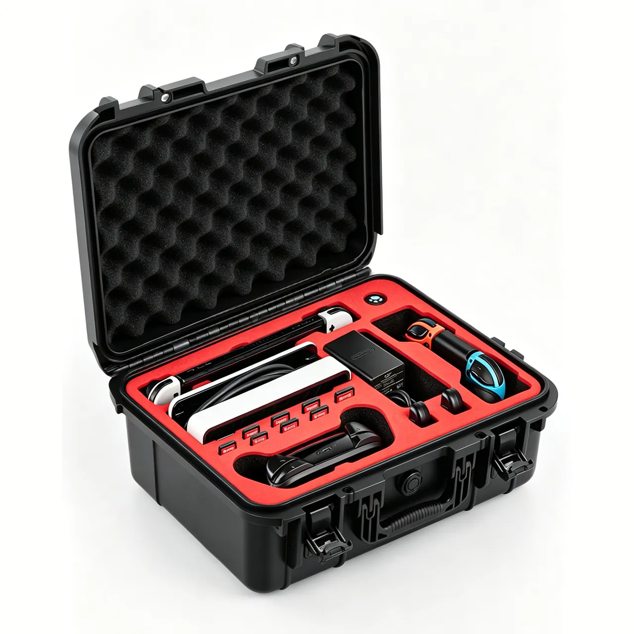
OEM/ODM customisation points. Welding equipment cases form a category with wide machine variation, frequently changing accessory combinations and medium batch volumes. Procurement strategy should be built around standardised cases, customised cavities and modular combinations. Use three to five standard case sizes, such as a small or medium welder case, a heavy frame case for large machines, a tool case, an accessory case and a cable case, to cover most combinations. Customise inserts by machine model while keeping the cavity common so inserts are interchangeable. Design tool, accessory and cable modules by series so one case serves many models. This spreads tooling cost across models; see case mould cost analysis. JUNZHJIA's standard approach for welding equipment is: accept machine drawings, 3D data or physical samples, produce a compartment and fixing proposal, confirm with a first-article trial fit, then run production with sampling and supply supporting test documentation.
Five dimensions for evaluating a supplier. Engineering capability, meaning the ability to produce a compartment proposal from machine model, centre of gravity and accessory list and to run a first-article trial fit. Materials and process, meaning foam density and batch consistency, overlay abrasion and shedding performance, seal section and hardness, and the oil-free and low-migration characteristics of the material. Test capability, meaning the ability to supply vibration, drop, stacking, water-ingress and salt-fog records. Delivery and capacity, meaning peak-season flexibility and lead-time reliability. Quality system, meaning sampling rules and non-conformance handling, summarised in custom case acceptance and AQL sampling.
Enquiry checklist. A practical enquiry should include: machine model and external dimensions; weight and centre of gravity; accessory list and quantities; a list of critical wear parts such as nozzles, contact tips, gauges and tungsten; material and surface treatment requirements; cleanliness and oil-free requirements, especially for oxygen-related accessories; transport mode and route; number of round trips; storage environment and temperature range; target IP rating; test requirements; marking and packaging documentation requirements; and annual volume with delivery cadence. For supplier selection see how to choose a protective case OEM factory.
Frequently Asked Questions
Q: Why does moisture control matter more than impact resistance for welding and cutting equipment?
A: Because welding equipment fails more often through gradual moisture and contamination than through a single drop. Take an inverter welder, which contains power semiconductor modules, electrolytic capacitors and control boards that corrode electrochemically in humid conditions, with saline sea freight especially unfavourable. During transport the machine has no self-heating to drive off moisture, so a closed unheated case settles at a relatively high internal relative humidity, and any day-night temperature swing produces condensation, which is often more damaging to electrical equipment than external rain. Moisture also affects consumables. Low-hydrogen and basic electrodes that absorb moisture and are not re-dried to the specified schedule produce porosity and can cause hydrogen-induced delayed cracking, which may appear hours to days after welding and is a serious risk for pressure-containing and dynamically loaded structures. The correct order of protection is therefore to control moisture and contamination first and mechanical shock second. Impact protection still matters, but it is a necessary rather than a sufficient condition. A combination of sealing, desiccant, a humidity indicator card and a pressure equalisation valve covers the moisture side well.
Q: Why should an inverter welder not be held by hard clamping in transit?
A: Because hard clamping transmits shock straight into the machine. The core of an inverter welder is a set of power semiconductor modules with heat sinks, mounted to the enclosure through solder joints and fasteners, and strong shock can cause solder fatigue and loosened fasteners. If the insert clamps the enclosure rigidly, external shock passes through case and insert to the enclosure with almost no attenuation and from there into the modules. The correct approach is full floating cushioning in low-rebound material: the machine is enveloped in a cushioning layer so shock energy is absorbed by material compression, while restraint structures limit travel to an acceptable range, with an empirical criterion of no more than 2 mm under hand pressure. It is also worth separating two component classes. Heavy items such as welders and wire feeders suit floating cushioning, while small fragile items such as nozzles, tungsten electrodes and ceramics suit separate compartments with soft separation. The two should not share one scheme.
Q: Why do torch and gun nozzles need separate protection, and how serious is the damage?
A: Because nozzles and contact tips directly govern weld and cut quality, and their damage signature is slight visible loss with large functional loss. The critical parts of a MIG or MAG gun are the contact tip, tip holder, diffuser and nozzle; for a plasma torch they are the electrode, tip and swirl ring. These parts have small bores and thin walls, and their tolerances affect gas flow and arc stability. A nozzle bore with a burr disturbs shielding gas flow and produces porosity and oxidation in the weld. A deformed contact tip bore drives wire off axis, producing spatter and undercut. A deformed or non-concentric cutting tip causes dross and a non-vertical cut face. On site it is often hard to tell exactly what has failed, so the operator replaces parts by trial, wasting labour and destabilising quality. Protect nozzles and contact tips with protectors so they take no load, give ceramic shields separate compartments with soft separation, and design a clearance cavity at the head so it cannot jam and be squeezed.
Q: How should gas accessories such as regulators and flashback arrestors be placed inside an equipment case?
A: The essentials are independent fixing, capped ports, unloaded gauge and no oil contamination. A regulator contains a diaphragm, adjusting spring, valve seat and stem that balance forces to hold outlet pressure steady, and it is sensitive to impact, contamination and overpressure. A drop displaces the spring or bends the stem, showing up as unstable outlet pressure, while dust and metal swarf entering the valve port prevent proper closure and cause leakage. Fix the regulator in its own box, guard the gauge, cap the inlet and outlet, and keep the adjusting knob unloaded. A flashback arrestor is a safety device containing non-return and flame-arresting elements, so its inlet and outlet must be capped against dust ingress, it must never be dismantled, it must not suffer mechanical damage, and it should be inspected or replaced at the supplier's specified interval. Two further requirements: regulators for oxygen and for fuel gas must not be interchanged, and oxygen in contact with grease presents a serious safety hazard, so liners, packaging materials and tools for oxygen-related accessories must be oil-free and must not share a cavity with oil-based consumables.
Q: Can an equipment case be used to transport a gas cylinder itself?
A: No. This is a compliance boundary that must be stated clearly. A cylinder holding compressed, liquefied or dissolved gas is generally treated as a pressure vessel, and its filling, storage, transport, use and inspection are governed by dedicated regulations and technical rules. In transport, most gases, including acetylene, oxygen, argon, carbon dioxide and propane, are classified as dangerous goods, and road, rail, sea and air carriage each fall under their own rule sets, such as dangerous goods road transport regulations within China, ADR for European road carriage, the IMDG Code for sea carriage and the IATA Dangerous Goods Regulations for air. These rules address the cylinder itself and its contents. An ordinary protective case does not qualify as a compliant cylinder transport device and should not be used to circumvent the applicable requirements. The correct role of an equipment case is to stow and protect the welder, torches, cables, regulator, hoses, tools and consumables, and to hold cylinder protective accessories such as caps, bumper rings and dedicated wrenches so that their loss does not compromise cylinder transport compliance.
Q: Why is the packaging protection for electrodes and wire more demanding than for the equipment itself?
A: Because the consequences of moisture uptake show up directly in weld quality, and not necessarily immediately. The coating of low-hydrogen and basic electrodes contains hygroscopic constituents. If a damp electrode is not re-dried to the specified schedule, moisture dissociates in the arc and hydrogen enters the weld pool, potentially causing porosity and hydrogen-induced delayed cracking. That cracking may appear hours to days after welding and is a serious risk for pressure-containing and dynamically loaded structures. Flux-cored wire contains flux powder that also absorbs moisture, producing porosity and unstable arc behaviour, while copper-coated solid wire corrodes after moisture uptake and the lost copper clogs contact tips and disrupts feeding. The most common transit problem with spooled wire is spool loosening: once the winding slackens, strands tangle and cannot be fed at all. Pack consumables with a barrier film, desiccant and a spool locating feature, and control storage humidity. Specific drying temperatures and times follow the electrode data sheet and the qualified welding procedure, and no process conclusion is offered here.
Q: What is the most common mistake when packing welding cables?
A: The most common mistakes are coiling too tightly and leaving connectors unprotected. Welding cable comprises a stranded copper conductor and a rubber or elastomer sheath, and it degrades progressively: once the sheath cracks, moisture and dust enter and the conductor oxidises; repeated flexing breaks individual strands, reducing effective cross-section so heating rises at high current; and terminals loosen and oxidise under repeated load, raising contact resistance and generating heat. Coiling below the minimum bend radius puts the inner sheath in tension and the outer in compression, and long storage leaves permanent deformation, so the coiling module must be designed around a coil diameter no smaller than the specified minimum bend radius. The second mistake is leaving connectors unprotected. A welding cable quick connector carries high current through a pin and spring contacts whose surface accuracy and spring pressure determine contact resistance, and impact deforms the pin or loosens the locking sleeve. Two further points are often missed. Rubber sheaths harden and embrittle at low temperature, so avoid sharp bends and dragging when handling cable in cold conditions. And cables and hoses should not share a cavity with oil- or solvent-based consumables over long periods, since rubber will swell and age.
Q: Should a welding equipment case be IP65 or IP67?
A: It depends on the transport route, the storage conditions and whether the case contains electronics or corrosion-prone parts. The IP code is defined in IEC 60529 and the equivalent Chinese standard is GB/T 4208. IP65 means dust-tight and resistant to water jets, suiting domestic and near-sea transport, covered transit and short-term site storage. IP67 means dust-tight and resistant to temporary immersion, typically 1 m for 30 minutes, suiting sea freight, open-air storage and high-humidity, high-salinity regions, and any case containing an inverter welder, control module or precision gauge. Two points deserve emphasis. First, a welder's own enclosure rating, expressed as IP21S or IP23S and similar per the arc welding equipment standard, and the sealing level of a transport case are different concepts and are not interchangeable. Second, whatever the rating, combine it with desiccant and a humidity indicator card and fit a pressure equalisation valve on routes with large temperature swings, because sealing keeps external water out but does nothing about moisture released by cables, gloves, paper and timber blocks inside the case, nor about internal condensation.
Q: How do I judge whether a welding equipment case can go back into service?
A: Establish explicit re-use criteria and a log. Check six items: whether the case has cracks, deformation or through damage, focusing on the base and corners; whether seals are hardened, cracked, debonded or permanently flattened, and in dusty or oily site conditions whether the sealing face has been contaminated; whether latches and hinges close and carry load reliably without looseness, corrosion or binding; whether inserts have collapsed, fractured, shed their overlay or lost compartments, since a collapsed insert directly causes location failure on the next trip; whether load blocks and base supports are deformed or cracked; and the condition of castors and the telescopic handle. Any failed item should be replaced before re-use. Two specific cautions apply to welding equipment. A long-serving insert accumulates metal dust and oil, and metal dust is conductive, so the insert must be cleaned or replaced before carrying a welder or control module. And liners and packaging materials associated with oxygen accessories must be confirmed oil-free; if they are not, they must not be used for oxygen-related accessories. A simple log recording case number, trip count, inspection records and usage history is the lowest-cost and most effective management tool.
Conclusion and Further Reading
Protecting welding and cutting equipment in transit is fundamentally a management problem of three object classes with three sets of logic. A welder is electrical equipment that fears moisture, static and shock. A gun or torch is a precision hand tool that fears impact, deformation and kinking. A regulator, flashback arrestor or hose is a safety-related pressure accessory that fears contamination, squeeze and oil. Put the three into one cavity and no matter how thick the case is, at least one dimension will fail. An effective plan is therefore not a sturdier toolbox but one that assigns load bearing, isolation, contact, moisture control and contamination control to the right structures, while bringing consumable moisture management and the gas accessory compliance boundary into the same picture.
The path to implementation compresses into five steps: sort the contents into three distinct zones, define the load path and fixing method, solve the fragile parts with compartments, sleeves and port caps, control moisture with sealing, desiccant and a humidity indicator card, and close the loop with transport testing and arrival functional checks including safety items. Two points bear restating. A gas cylinder itself is a pressure vessel and a dangerous good whose transport must follow mandatory regulations, and an equipment case is not a substitute for a compliant transport arrangement. Equipment used in a hazardous area must follow the owner's hot work and explosion-protection rules. Where a compartment and fixing proposal is needed for specific machine models, accessory lists or field-service scenarios, provide drawings, 3D data or physical samples to JUNZHJIA and request a drawing plus a first-article trial fit.
Further Reading