

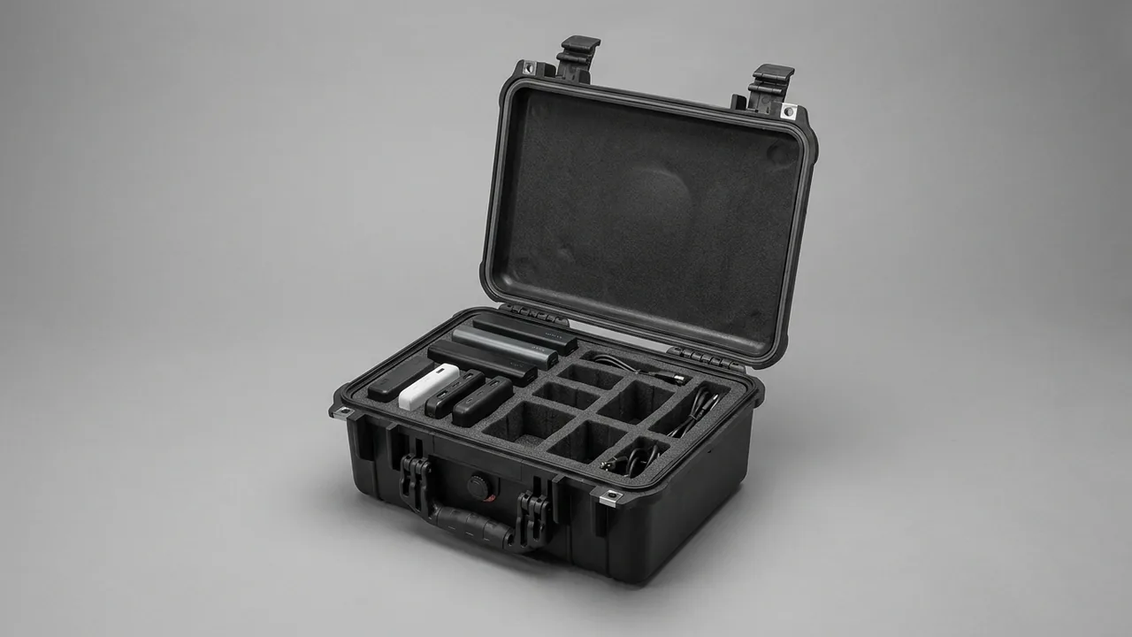
Metro tunnel ventilation equipment is supplied section by section: each station has tunnel ventilation fan rooms and jet fan groups at both ends, and the components for one line are typically split across a dozen or more shipments, leaving the factory for sites where the civil structure is still open to the sky. The conclusion up front: the design objective for a metro tunnel fan component case is not simply to fit the parts in. It is to satisfy four conditions at once, namely cleanliness and integrity of the impeller balance surfaces, roundness hold of thin-wall casings and flow ducts, dry and uncompressed acoustic media inside silencer sections, and electrical reliability of damper and fire damper actuators, while still allowing the contents to be lifted straight into position when the case is opened in a wet, dusty tunnel. Tunnel fans are fire-mode equipment that must operate reliably under a fire scenario, so a single impact mark in transit or one damp silencer section can surface during acceptance sampling or during an actual incident. This article works through each component family, giving protection parameters, the standards behind them, and practical methods for insert and lifting design, for metro MEP contractors, ventilation equipment makers and maintenance organisations.
Site conditions in tunnel work are far harsher than a normal factory. The unloading point is often an un-surfaced muck-out shaft with standing water in the rainy season and heavy airborne dust, and lifting space is constrained by the shaft and cross passage. Shipping fan components in timber crates filled with loose foam chips produces five recurring problems on arrival. Impeller blades are scratched by debris and loose screws, and the installed fan fails a balance check with low-frequency noise. Thin-wall casings are flattened by stacking, flange gaps exceed tolerance and the joint leaks. Glass wool in silencer sections absorbs moisture and cakes, and insertion loss collapses. Actuators take in humidity, limit switches fail, and the fire damper cannot close on a 70 degrees C fusible link signal. Heavy casings distort at the instant of lifting because the lifting points were chosen badly. These failure modes overlap with the rotating machinery protection described for centrifugal blower component cases, but tunnel fans add a specific combination: long cylindrical shells, thin walls and fire-safety reliability at the same time.
Contents
- Metro tunnel ventilation components and their transport damage map
- Axial fan impellers and hubs: protecting the balance surfaces
- Casing and flow duct: preventing distortion in thin-wall long cylinders
- Silencer sections and splitters: keeping absorbers dry and uncompressed
- Dampers and fire damper actuators: moisture and vibration control
- What the wet, dusty tunnel environment demands from case sealing
- Insert structure for long cylinders: three-point support and axial restraint
- Lifting design for heavy items and case load paths
- Stainless and galvanised parts: corrosion control and galvanic isolation
- Vibration isolators and spring mounts: transport locks and release marking
- Insert material selection: where EVA, PE, PU and EPP each fit
- Transport validation: ISTA, GB/T 4857, ASTM D4169 and MIL-STD-810H
- Marking, counting and site handover procedure
- Frequently asked questions
- Conclusion and further reading
Metro tunnel ventilation components and their transport damage map
The ventilation package for a metro line normally falls into five supply groups: tunnel ventilation fans and jet fans, silencer sections and silencer bends, dampers and fire dampers, actuators with local control boxes, and vibration isolation with support accessories. Some lines also include reversible high-temperature fans and smoke extraction fans. The geometries differ enormously. A jet fan is a slender cylinder 3 m to 5 m long and 0.6 m to 1.2 m in diameter. A tunnel ventilation fan is a large axial machine whose casing can exceed 2 m in diameter. Silencer sections are typically square shells 1 m to 2 m across and 2 m to 4 m long. Packing logic must therefore classify by geometry rather than by weight, otherwise long cylinders end up being squeezed diagonally.
The table below lists the main weak points per component together with a recommended zoning strategy, and it can serve as the first check layer of a packing list.
| Component | Main transport weak point | Recommended zoning |
|---|---|---|
| --- | --- | --- |
| Axial impeller and hub | Rolled blade edges, scratched balance surfaces, pressure marks on the hub fit | Individual cavity, elastic stops at both hub ends, never stacked |
| Casing and flow duct | Loss of roundness, chipped flange faces, coating damage | Temporary internal support rings, three-point axial support |
| Silencer section | Damp and caked acoustic media, dented perforated plate, flattened end gaskets | Moisture barrier film plus end guards, no side stacking |
| Damper and fire damper | Distorted blade, seized bushings, displaced fusible link | Blade locked closed, limit blocks at both ends |
| Actuator and control box | Humidity ingress, failed limit switch, loosened terminals | Antistatic bag, desiccant, damping pads, separate soft cavity |
| Isolators and spring mounts | Spring set change, rubber ageing, bent adjusting bolts | Shipping lock pins stay fitted, compartmentalised as one unit |
| Flexible connectors and bolts | Torn fabric connector, corroded bolts, curled gaskets | Connector rolled to over 300 mm diameter, bolts bagged by size |
Looking at the damage mechanics, transport failures in tunnel fan components have two high-frequency sources and both relate to length. First, when a long cylinder rests on two supports inside a vehicle, the unsupported mid-span bends repeatedly under low-frequency vibration in the 3 Hz to 15 Hz band, and the accumulated effect shows up as out-of-roundness. Second, the end flange behaves as a load-bearing face during stacking or forklift handling, and once flange flatness is lost the field joint will leak. By contrast the heaviest single item, the large fan casing, is rarely the one that distorts, because its own mass and stiffness protect it. The genuine weak point is the slender shell of a jet fan: long and thin.
There is another common misjudgement in practice: treating a silencer section as an ordinary sheet-metal shell. In reality its mass sits in the perforated plate and the acoustic media, and under lateral compression the internal structure collapses as a whole. That collapse is hard to see externally and only appears when insertion loss is sampled on site. A silencer section must therefore come with an explicit statement of which face points down, how much compression is permitted, and which orientations are prohibited.
Axial fan impellers and hubs: protecting the balance surfaces
An axial fan impeller consists of a hub, blades and, on some models, a variable-pitch mechanism. Blades are usually cast aluminium, glass reinforced plastic or welded steel, with diameters from 0.4 m on a jet fan to 1.6 m on a tunnel ventilation fan. Balance quality is normally controlled to ISO 1940-1 grade G6.3 or tighter, and a single point of mass displacement will show up as low-frequency noise and shaft vibration once installed.
Three specific actions protect the balance surfaces. First, blade leading and trailing edges carry the tightest profile accuracy, so they must not touch a hard insert directly. Use closed-cell EVA or PU of 20 mm to 30 mm thickness, shaped to follow the aerofoil rather than left as a flat pad. Second, the hub bore and mating face are datums, so two impellers must never be stacked hub face to hub face, because static stacking load leaves marks on the mating face and the fit has to be reworked at site. Third, the adjusting screws and scale marks of a variable-pitch mechanism are soft information. Fit a protective cover and a tamper-evident label, so the reference position is not lost and the whole machine does not need re-calibration.
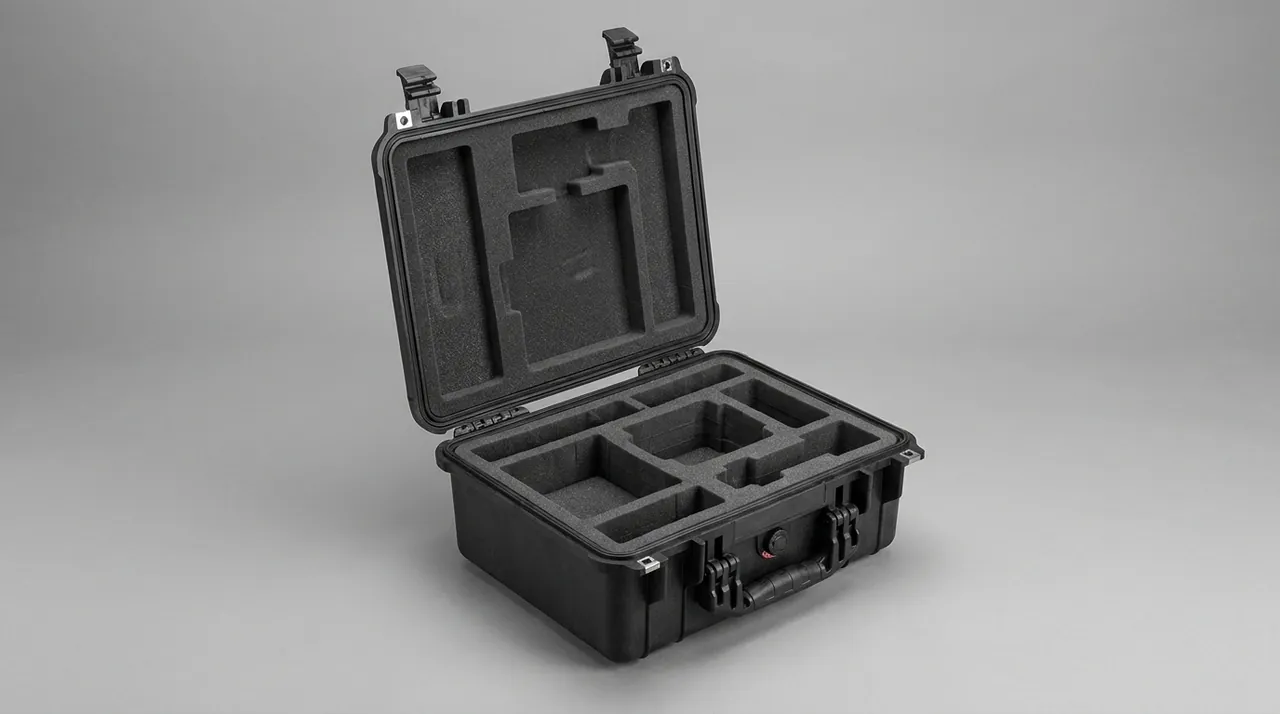
For glass reinforced plastic and composite blades there are two additional cautions. The first is to avoid prolonged over-limit bending, because the resin matrix creeps and the profile will not recover. The second is to avoid direct contact with galvanised or carbon steel parts, which under damp conditions leaves metal ion contamination and galvanic corrosion marks. Give each blade its own cavity lined with neutral PE or EVA.
Rule of thumb: a cast aluminium axial impeller 1.2 m in diameter commonly weighs between 25 kg and 60 kg. Its permitted residual unbalance at grade G6.3 is often only in the tens of gram-millimetre range, which corresponds to a few grams applied at the blade tip. That is why a single rolled blade edge is enough to fail a site vibration test.
Site handover of an impeller should follow a three-step confirmation. Inspect the hub mating face for pressure marks, run a hand along the blade leading edge to feel for rolled edges and burrs, and check the blade pitch scale against the factory record. If any step is in doubt, do not lift the impeller into position yet.
Casing and flow duct: preventing distortion in thin-wall long cylinders
Transport distortion of thin-wall shells is the hardest problem in tunnel fan component protection, because it is invisible but measurable. A shell 3 mm thick and 1.5 m in diameter already deflects noticeably under its own weight, and if it rests on only two points inside a case the unsupported mid-span becomes a vibration amplifier.
The solution has three steps. Step one is internal support: fit two or three temporary timber or aluminium support rings inside the shell so that the circular section becomes a stiff ring for the duration of transport. The ring outside diameter should be slightly smaller than the shell bore, with soft facing at the contact so the internal coating is not scratched, and on a fan that already carries its impeller the rings must clear the blade swept area. Step two is external three-point support: place curved saddles at front, middle and rear along the shell. The middle saddle works best at 0.45 L to 0.55 L, the saddle radius should match the shell outside diameter, and the contact length should be at least 120 mm so that the load is spread over an area rather than a line. Step three is axial restraint: fit limit blocks outboard of the flanges at both ends and add straps, creating a two-way constraint so the shell cannot slide along its axis and strike the case wall.
| Shell length to diameter ratio | Support points | Middle support position | Internal rings |
|---|---|---|---|
| --- | --- | --- | --- |
| Under 3 | 2 | Not applicable | 0 to 1 |
| 3 to 6 | 3 | 0.45 L to 0.55 L | 1 to 2 |
| 6 to 10 | 4 | 0.33 L and 0.67 L | 2 to 3 |
| Over 10 | 5 or more | Evenly distributed | 3 or more |
The flange is the second focus. Tunnel fan flanges are usually fabricated from angle or flat bar, and face flatness directly controls the leakage rate of the field joint. Fit a temporary guard plate over the face with a 5 mm to 10 mm resilient pad between guard and flange, and fasten the guard through the existing bolt holes rather than taping it on. Tape peels away after rain soaking, and a guard left in place becomes a foreign object. Where the holes are slotted, use the original positions so no reaming is needed.
Coating protection matters too. Tunnel fans usually carry an epoxy zinc-rich primer with a topcoat, and some line specifications call for several hundred hours of neutral salt spray testing to GB/T 10125 without red rust. If the insert contains soft PVC with migrating plasticisers, prolonged contact makes the paint film bloom and blister, which on inspection is easily misread as a factory coating defect.
Silencer sections and splitters: keeping absorbers dry and uncompressed
Splitter silencers and dissipative silencers are the main noise control devices in tunnel ventilation, and their performance depends entirely on the pore structure and moisture content of the acoustic medium. Once the moisture content of glass wool or rock wool rises, mid and high frequency absorption falls sharply, and caked media cannot be restored to its original porosity even after drying. Protecting a silencer section in transit is therefore really two jobs: keeping it dry and keeping it uncompressed.
Moisture protection works in three layers. The first is end face sealing. A silencer section normally leaves the factory with perforated plate and facing already fitted; for transport, add a peelable PE moisture barrier over the whole end face so rain and dust cannot enter through the perforations. The second is case sealing: load the section into a case rated IP66 or better, cutting off spray water and airborne dust, with the classification defined by IEC 60529 and its Chinese equivalent GB/T 4208. The third is internal humidity management: place indicating desiccant inside so a colour change shows directly when the limit has been exceeded, and for sea freight or long overland routes add vapour phase corrosion inhibitor material to protect the perforated plate and fasteners.
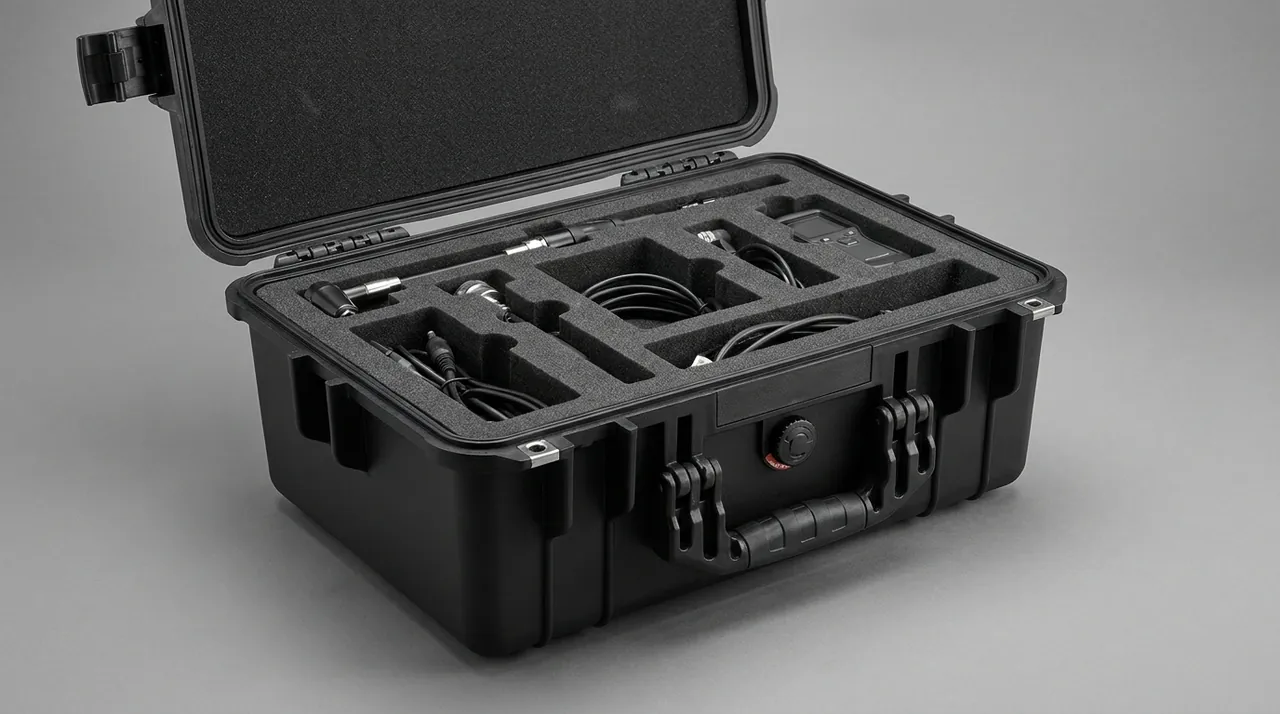
Compression protection is about designing the load path. The perforated plate and acoustic medium of a silencer section can carry almost no lateral load, so inside a case it can only exist in a small number of permitted attitudes, typically end face down or standing along its axis, and it must never be multi-stacked or squeezed sideways. The usual approach is to arrange sections longitudinally along the long side of the case, separate each section with a PE or EPP divider at least 30 mm thick, and wedge the dividers against the case wall with support battens so that stacking load travels through divider and batten into the case frame instead of through the acoustic body. If two silencer sections must share one case, split them into an upper and lower layer and make sure the lower section lands fully on a load-bearing pallet.
Loose splitters for site assembly need finer treatment. Each splitter is light but there are many of them and they chip easily. Sort them into stacks of the same size, place a rigid divider between stacks, wrap each stack in a moisture barrier bag, and give them a dedicated compartment so they cannot slide during handling and tear the facing. Once the glass fibre facing cloth is hooked open, loose fibre escapes, which is a clear health and safety issue for the installers on site.
Dampers and fire damper actuators: moisture and vibration control
Dampers and fire dampers in tunnel ventilation perform mode switching and fire compartmentation, and their critical parts are not the body but the actuation package: electric actuators, thermal fusible links, limit switches and local control modules. The common enemy of all of them is moisture and vibration, not weight.
- Actuator: pack in three layers, an antistatic shielding bag, an individual EVA cavity, and four-sided restraint, with the cavity wall in contact but not under pressure. If the output shaft is turned by an external force in transit, the internal clutch and limit cams can shift, so lock the shaft with a shipping pin or clamp.
- Thermal fusible link: a single-action device, so avoid sharp temperature swings and mechanical shock. Store it in a separate small box with the factory actuation temperature clearly marked, to prevent a wrong part being fitted on site.
- Limit switch and terminals: the most moisture-sensitive items in the group. Place desiccant inside the case, check that the gasket is intact, and consider vapour phase corrosion inhibitor for copper contacts and busbars.
- Local control box: internal boards are resonance sensitive and must be restrained on four sides rather than left suspended, with at least 20 mm of cushioning clearance between board and case wall.
Fire damper blades should stay in the closed position during transport and be secured with limit blocks. If a blade is distorted by impact, the fusible link will release but the blade will not seat, and the smoke sealing function is lost. Blade and seat gaskets are usually silicone rubber or intumescent graphite and compress easily, so they must not sit under sustained load or come into contact with oil.
Note: the reliability of a fire damper is only proven under fire conditions, while transport damage is invisible during ambient acceptance. Ship actuators and valve bodies in defined zones of the same case, and state on the handover sheet that limit blocks and shipping pins must be removed before installation.
Where an actuator contains a solenoid or a motor, long storage also raises the question of insulation resistance. Replaceable desiccant combined with an IP66 case or better holds a low-humidity environment across both the transport phase and the site storage phase, which suits the rhythm of MEP installation better than one-way vacuum packing. If the case uses a pressure equalisation valve, sealing classification can be retained while the differential pressure caused by day-night temperature swings is relieved; the mechanism is described in protective case pressure equalisation valves.
What the wet, dusty tunnel environment demands from case sealing
Site conditions during tunnel construction can be summarised as three highs and one low: high relative humidity, often above 80 percent RH and close to saturation where the lining weeps; high airborne dust from shotcrete, cutting and muck removal; and frequent temperature swings, all with poor ventilation. These conditions feed directly into case sealing selection.
| Rating | Dust protection | Water protection | Suitable scenario |
|---|---|---|---|
| --- | --- | --- | --- |
| IP54 | Limited dust ingress | Splash resistant | Factory to covered warehouse shuttle |
| IP55 | Dust protected | Water jet resistant | Road transport, temporary material shed |
| IP65 | Dust tight | Water jet resistant | Short open-air storage on site |
| IP66 | Dust tight | Strong water jet resistant | Shaft head unloading, open storage, wet regions |
| IP67 | Dust tight | Short-term immersion | Standing water, unsheltered unloading in rain, sea freight |
The recommended floor for metro tunnel fan components is IP66. The reason is that unloading points often have no canopy, the forklift sets the case down in the open, and if the lifting window is taken that day the case may stay outdoors overnight or for several days. IP66 withstands strong water jets and continuous dust, while IP67 additionally covers standing water and short immersion. It is important to remember that an IP rating describes only how hard it is for external water and dust to enter, and does not mean internal humidity stays controlled, because internal humidity also depends on the moisture vapour transmission rate of the gasket, the breathing effect from thermal cycling and the desiccant capacity. For moisture-sensitive parts such as actuators and control modules the correct approach is always a sealed enclosure plus internal humidity management. Where the same case family must also cope with loading in rain, the structural points about gasket section and latch pressure in IP67 protective cases are worth reviewing.
Dust performance is also tied to the door architecture. The fit between hinge, latch and gasket determines whether a dust path remains after closing. Tunnel dust is fine grained and highly adherent; once it enters a slide or a latch mechanism it accelerates wear and reduces gasket compression. The structural points are common with case hinge, latch and seal construction, but tunnel work adds one requirement: the case must be closable and lockable with one hand through a work glove.
Insert structure for long cylinders: three-point support and axial restraint
The design objective for a long cylinder insert can be stated in one sentence: make the load travel through saddle and frame rather than through the shell wall. Four elements deliver that.
The first is saddle shape. Contact between a curved saddle and the shell should be an area contact, not a line contact. A contact arc of at least 15 percent of the shell circumference, corresponding to a width of at least 120 mm, is a reasonable target. Saddle material is best chosen from EVA or PE in the 30 to 50 Shore A hardness range, which cushions while still spreading load.
The second is the number and position of support points. Too few points cause mid-span bending, while too many create over-constraint so that an impact on the case is transmitted straight into the shell. The length to diameter table above is a sound starting point.
The third is axial restraint. The largest displacement direction for a long cylinder is usually axial, because vehicle acceleration, braking and gradients all make the shell slide along its axis. Use limit blocks at both ends bearing on the flange outer faces and fixed to the case frame, plus a strap over the top of the shell anchored to the frame, which provides the return constraint.
The fourth is the internal support ring. Its job is to turn a thin circular section into a stiff ring for the duration of transport, and for ratio above 6 it is close to mandatory. Rings must be removed immediately after unloading and collected in one place, so that none is left inside to fall out during lifting.
Unlike a long cylinder shipped as part of an assembled machine, loose flow ducts, spools and flanged pipe parts should be compartmentalised by diameter and layered by length. A compartment insert has a second benefit: it supports counting. Each compartment corresponds to one part, so the quantity can be verified as soon as the case is opened. For a case that goes round repeatedly, such as a maintenance spares case, a removable divider system allows positions to be changed without replacing the whole insert, which helps when a different fan model has to be carried.
Lifting design for heavy items and case load paths
Heavy items in tunnel ventilation include large fan casings, assembled machine baseplates and heavy silencer bends, with individual weights commonly between 200 kg and 1200 kg. Protection for these must be designed together with the lifting method, because a single badly judged lift will invalidate every insert restraint no matter how good the case is.
Lifting design comes down to three decisions.
The first is where the lifting points belong. There are two approaches. Either the case carries its own lugs, welded or bolted to the frame, arranged in fours and designed so that the sling angle at the lug is between 45 and 60 degrees, with the included angle never exceeding 90 degrees because the force in each leg rises steeply beyond that. Or the component carries its own lugs, and the case provides an opening or a removable cover at that position so the rigging acts directly on the component, with the case serving only as protection. The first approach transfers and repositions more easily; the second suits very large or very heavy items.
The second is centre of gravity marking. Off-centre loading inside a case is unavoidable, so the case must carry centre of gravity marks and lift-point marks on all four sides, ideally with graphical symbols as well as text. Graphical symbols for packing and transport are specified in GB/T 191, and the general technical conditions for mechanical and electrical product packaging in GB/T 13384.
The third is the interaction between insert and lift. At the instant of lifting the component sees a quasi-static load amplification, and if the insert saddles are not already carrying the main load the component will shift inside the case. Saddles for heavy items should therefore take the load the moment the part is set down, while leaving at least 30 mm of cushioning clearance for impact. The load-bearing structure at the bottom of the case, whether pallet beams or skids, must spread concentrated load toward the forklift pockets or lifting frame so that the base panel does not dish locally.
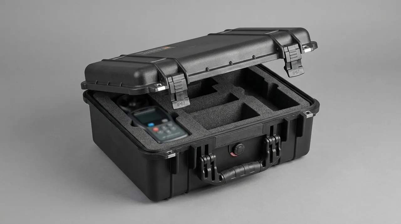
For a case that is lifted as a unit, two site details matter. Fit lifting sleeves or corner protectors before loading, so the slings do not cut into the case walls and leave pressure marks. Then remove internal support rings and transport limit blocks immediately after unloading, because if these temporary items are lifted into place with the component they tend to be forgotten inside a duct and become a foreign object hazard. Large gate components in water conservancy works face a similar problem, and the practice around heavy item lifting and recovery of restraint parts in dam gate component cases is a useful reference.
Stainless and galvanised parts: corrosion control and galvanic isolation
Corrosivity in a tunnel comes from two directions: chloride from groundwater and leakage, and metallic dust with acidic gases generated by train operation. That is why fan components make wide use of stainless fasteners, hot dip galvanised brackets and epoxy coated casings. Handled badly in transit, the protection can itself introduce a new corrosion source.
The first issue is galvanic isolation. When a stainless part touches a galvanised or carbon steel part directly, a galvanic couple forms in a damp environment and the more active metal corrodes faster. The working practice is to compartmentalise by material. Where parts must share a cavity, separate them completely with a neutral PE or EVA divider. Bag fasteners by material and label them, so they are not mixed on site.
The second issue is the service life of the rust prevention. Exposed threads, keyways and flange sealing faces should be coated with a durable rust preventive grease or covered with a peelable protective film. Note that grease can run at high temperature and contaminate other parts, so fit a sleeve after coating. For sea freight, add vapour phase corrosion inhibitor material inside the case to create a protective atmosphere around metal surfaces, keeping the carrier, usually non-woven or foamed material, out of the same cavity as acoustic media so that volatiles do not affect absorption.
The third issue is interpreting salt spray data. GB/T 10125 specifies a neutral salt spray test method, and test duration does not map linearly onto field survival time. When accepting a coating system the buyer should focus on film thickness and adhesion results, such as cross-cut or pull-off tests, and treat salt spray data as supporting evidence rather than the sole criterion.
The fourth issue is cleanliness. Tunnel dust and the metal swarf generated during transport, if carried into an impeller cavity or a bearing housing when the case is opened, cause far more serious problems than an appearance defect. Avoid open-cell foam that sheds inside the case and use closed-cell material instead, and apply peelable protective film to critical mating surfaces before packing so it can be stripped immediately before installation. This follows the material selection principles set out in the custom foam insert guide.
Vibration isolators and spring mounts: transport locks and release marking
A tunnel fan needs vibration isolation when it runs, and the isolation elements are precisely the weak parts during transport. A spring mount left free will extend and compress repeatedly with vehicle vibration and the spring may take a permanent set. A rubber mount under sustained compression develops compression set and rises in hardness. The transport rule is therefore lock and mark.
In practice, spring mounts come from the factory with a shipping pin or locking bolt that pre-compresses the spring close to its working position. Before loading, confirm the lock is in place and add timber battens to tie the equipment base rigidly to the case frame, so that transport loads bypass the springs. After unloading, the locks are removed only once the equipment is in position and full load has been applied, and the sequence must not be reversed or the base will shift abruptly.
| Isolation element | Risk in transport state | Handling | Release condition |
|---|---|---|---|
| --- | --- | --- | --- |
| Spring mount | Repeated cycling changes free height | Locking pin holds working position | Equipment set and load applied |
| Rubber pad | Compression set, increased hardness | Unload with spacer blocks, avoid sustained compression | Spacers removed before fitting |
| Hanger spring mount | Bent rod, displaced spring | Support the rod, lock the spring | After pipework or equipment load is applied |
| Inertia base and counterweight | Displacement impact, damaged surfaces | Two-way limit blocks | After installation is complete |
Another easily missed detail is the difference between seizure and displacement. Field reports of uneven mount heights after installation sometimes trace back to a shipping lock that was not compressed to the specified position, and sometimes to locks removed in the wrong order, which leaves the springs at scattered free heights. To avoid disputes, add a status card inside the case listing lock positions, removal sequence and inspection points, and have both parties sign at handover.
For flexible pipe connectors, roll the fabric connector into a cylinder of at least 300 mm diameter and secure it with straps; never fold or flatten it. A crease in the fabric becomes a stress concentration and it will crack early in service.
Insert material selection: where EVA, PE, PU and EPP each fit
Insert selection should not rest on softness alone. Density, resilience, moisture vapour transmission, shedding tendency and weathering all matter. The table below gives the four material families commonly used for tunnel fan components and where each fits.
| Material | Density range | Main advantage | Main limitation | Suitable parts |
|---|---|---|---|---|
| --- | --- | --- | --- | --- |
| EVA | 40 to 90 kg/m3 | Good resilience, easy to form, contoured cavities | Can soften under sustained heat | Impellers, actuators, precision parts |
| PE | 25 to 60 kg/m3 | Low cost, good water resistance | Moderate resilience, collapses after repeated compression | Large dividers, pallet cushions |
| PU | 30 to 80 kg/m3 | High load capacity, abrasion resistant | Hydrolyses, needs care in damp service | Heavy saddles, load-bearing blocks |
| EPP | 20 to 60 kg/m3 | Excellent resilience, multi-trip, oil resistant | Higher unit price, mould cost | Returnable case inserts, silencer dividers |
For tunnel fan components a layered combination works best. The layer touching a precision surface uses low density EVA at 40 to 50 kg/m3 to conform without scratching. Saddles and dividers that carry the main load use PU or high density EVA at 70 to 90 kg/m3. The cushioning layer against the outer case wall uses PE or EPP to cut cost and improve water resistance. For cases that go round many times, EPP offers the better payback because it recovers well after repeated compression.
Beyond material there are two process points. The first is cavity tolerance: the inner contour should be about 1 mm to 3 mm larger than the part on each side, so the fit is close without pressure. An interference fit does restrict movement, but it loads the part continuously and can damage coatings. The second is attachment method. Use replaceable mechanical fastening such as nylon rivets or hook and loop rather than full-surface adhesive, so a locally damaged insert can be replaced and tunnel dust can be cleaned out. Further comparison of foam materials and forming processes is given in the custom foam insert guide.
For maintenance scenarios that need fast handling, a drawer-style insert with compartment labels works well: each compartment maps to one part with a name and quantity, so the case can be checked against the list without removing the whole insert. That matches the short-window, quick-handover rhythm of MEP installation.
Transport validation: ISTA, GB/T 4857, ASTM D4169 and MIL-STD-810H
The reliability of a protective case cannot rest on description; it must be tied to a verifiable test programme. Validation for tunnel fan component cases usually involves four standards families, each doing a different job.
| Standard | Full name or nature | Main scope | Use for fan component cases |
|---|---|---|---|
| --- | --- | --- | --- |
| ISTA series | International Safe Transit Association test procedures | Drop, vibration, stacking, concentrated impact | Whole case simulated distribution, verifying insert and restraint performance |
| GB/T 4857 series | Basic tests for transport packages | Drop, stacking, vibration, spray | General domestic acceptance basis |
| ASTM D4169 | Standard practice for performance testing of shipping containers and systems | Test sequence assembled from a distribution cycle | Combined validation for multi-leg sea freight |
| MIL-STD-810H | Environmental test methods, used as a method reference only, not a military certification | Vibration, shock, temperature and humidity, salt fog methods | Guidance on method and severity selection |
One point must be stated clearly. MIL-STD-810H is an environmental test method standard. Citing it means the specified test methods are used; it does not mean the product holds any military certification, and outward documents should avoid claiming military standard approval.
Four practical points guide test programme design. First, the test article must be the production configuration, with the same gasket section, latch count, wall thickness and insert structure as the delivered goods, otherwise the result cannot be transferred. Second, record insert compression, fastener torque and initial desiccant state before the test, then re-measure each item afterwards, focusing on permanent saddle indentation and any displacement of limit blocks. Third, match shock severity to the real logistics chain: tunnel unloading points are frequently on un-surfaced ground, so drop and concentrated impact risk is higher than in ordinary factory distribution. Fourth, for the long cylinders described here, vibration testing should specifically look for a measurable roundness change at mid-span, an item that general test sequences tend to miss. Where a third-party report is required, ask the supplier to provide the test plan and raw records with the case; a fuller breakdown of the procedures is given in ISTA transport testing procedures and MIL-STD-810H environmental test methods.
Marking, counting and site handover procedure
Metro projects are multi-batch, multi-station and multi-contractor. The same fan model may be shipped to different stations in separate lots, which makes the marking system as important as the insert design.
Marking should carry four families of information. First, the graphical symbols for packing and transport specified in GB/T 191, covering keep dry, keep away from rain, do not roll, centre of gravity and lift here. Second, item and batch information: contract number, station name, equipment tag and packing list reference. Third, a text statement of protection rating and handling requirements, for example sealed to IP66, reseal after opening, or desiccant fitted, reseal within 24 hours of opening. Fourth, centre of gravity and lifting point marks, which must appear on all four sides of heavy items. General technical conditions for the packaging follow GB/T 13384.
Site handover works best on a three-list check. The packing list confirms quantity and specification against the goods. The accessory list confirms bolts, gaskets, special tools and spares. The status sheet records gasket condition on opening, desiccant indicator colour, and the position of internal support rings and locking devices. Once the three agree and both parties sign, the responsibility boundary is clear should damage appear later.
Two site details belong in the handover requirements. If the gasket is found indented by grit, replace the gasket rather than patching it with tape. During site storage the case should stay locked and upright, so that rain is not driven along the door seam for weeks. These practices align with the gasket and hinge care advice in how to clean a protective case. For a maintenance case that is opened repeatedly to take out spares, specify a replaceable gasket and a weather-resistant latch, and keep a reseal check record after each use.
Frequently asked questions
Q: Should a tunnel fan impeller be stored vertically or laid flat in transit, and which better protects the balance? A: It depends on the impeller architecture, so there is no single answer. For an axial impeller with a long hub, laying it flat with the axis vertical and the hub end face downwards is preferred, because gravity then acts along the axis and creates no bending moment at the blade root, and the hub mating face is not carrying stacking load from parts above. For an impeller with a large diameter and long blade overhang, such as a tunnel ventilation fan impeller above 1.6 m, laying it flat leaves the blade overhang carrying its own bending moment, so standing it with the axis horizontal and the blades supported at three points is better, with saddles under the disc and either side of the tips. In either attitude the profile must not touch a hard surface, the hub mating face must not carry stacking load, and the variable-pitch scale must be protected. If several impellers share one case, separate adjacent impellers with a rigid divider at least 20 mm thick and keep at least 30 mm of cushioning gap between them. Once the case is loaded, re-check impeller attitude and confirm that limit blocks and straps are not loose, then check strap tension every 500 km on a long route.
Q: Can a damp silencer section be dried and reused, and how do we decide whether it is still serviceable? A: Distinguish between damp and caked. Simple moisture uptake, where moisture content has risen but the pore structure is intact, can largely be recovered by low-temperature drying, typically 60 to 80 degrees C with airflow until constant weight, followed by a moisture content check. Caking is different: the acoustic medium has been compressed repeatedly while damp, the fibres have formed a dense layer and porosity has dropped irreversibly. In that state, even when moisture content returns to the factory level, mid and high frequency absorption stays clearly low and the acoustic core must be replaced. Two checks help decide. First, visual and tactile inspection: caked areas feel hard and do not spring back, and a cut section shows fibre delamination. Second, sample insertion loss or airflow resistance and compare with the factory data; a deviation above 10 percent means rejection. For prevention, use a case rated IP66 or better with indicating desiccant, fit a peelable moisture barrier over the end faces, and prohibit side stacking during transport and site storage. Isolate and tag any section found damp rather than passing it straight to installation.
Q: Does a fire damper actuator need to be shipped separately, or can it stay fitted to the damper body? A: Shipping the actuator fitted to the damper body is workable and more common, provided specific measures are taken. The advantage of keeping it fitted is that the commissioning state achieved at the factory is preserved, avoiding re-calibration on site. The risk is that the actuator projects beyond the damper outline and becomes the first point to take load during stacking and handling. The practice should therefore be: keep the actuator on the body, but fit a separate guard or cavity outboard of it that is strong enough to carry the stacking load inside the case; lock the output shaft with a shipping pin so the blade cannot be pushed by an external force and displace the limit cams; fit a cover over the terminal block and secure the leads, coiling them into a loop of at least 100 mm diameter so the root is not pulled. If the project requires separate shipment, pack the actuator as precision electrical equipment with an antistatic bag and a soft-lined cavity restrained on four sides, add desiccant, and record on the handover sheet the functional test required after refitting, covering full stroke operation, limit feedback and fusible link simulation.
Q: For a large tunnel ventilation fan casing, should the maker or the case supplier provide the lifting lugs, and how do we choose? A: Three factors drive the choice: individual weight, number of lifts, and whether the case is reused. If a single item weighs under 500 kg and is lifted only a few times, case-mounted lugs save site operations. Arrange four lugs, design each for at least 1.5 times its share of the total weight, keep the included sling angle within 90 degrees, and locally reinforce the case frame at each lug. If a single item exceeds one tonne, or the component already has a proven lug design, prefer lifting directly on the component lugs, with a removable cover or a rigging window at that position in the case, so the case only protects and transports. This avoids fatigue cracking in the case frame after repeated lifts. If the case is reused many times, add non-destructive testing sampling at the lug roots and inspect welds and bolts after each use. In every case, mark the centre of gravity and lifting points on all four sides and supply a lifting drawing giving sling length, included angle and permitted eccentric loading.
Q: Should the case be rated IP66 or IP67, and is IP68 ever justified in a metro tunnel? A: IP66 is normally the floor, IP67 is the recommendation, and IP68 is usually unnecessary. IP66 means dust tight plus protection against strong water jets, which covers open unloading at a shaft head, continuous dust and short heavy rain, the most common conditions in tunnel work. IP67 adds short-term immersion on top of IP66 and suits unloading areas with standing water where the case base can be flooded, so upgrading to IP67 is worthwhile in a rainy construction area. For IP68 the immersion depth and duration are agreed between manufacturer and user, and the cost is a more complex seal, harder opening and closing, and a gasket that is harder to maintain once worn, which is poor value for a maintenance case that is opened frequently to take out spares. Remember that an IP rating addresses only ingress of external media; the long-term reliability of actuators and control modules also depends on internal humidity management. The recommended combination is an IP66 or IP67 enclosure with replaceable desiccant, a humidity indicator and a pressure equalisation valve, and resealing within 24 hours of every opening.
Q: Why must an internal support ring be fitted inside a long cylinder, and what happens without one? A: The support ring raises the section stiffness of a thin circular shell during transport, temporarily converting a buckling-prone thin wall into a stiff ring. Without one the consequences are progressive and often leave no obvious external defect at the end of the journey, while the dimensions are already out of tolerance. The shell bends repeatedly under low-frequency vibration and the roundness deviation accumulates beyond design tolerance. The flange face then goes oval, the field joint shows uneven gaps and leakage rises. If the impeller is already fitted, tip clearance becomes uneven around the circumference, producing aerodynamic noise and vibration, and in severe cases the blade tip scuffs the shell wall. For a shell with a length to diameter ratio above 6 the ring is close to mandatory, with one ring every 1.5 m to 2 m of length. Fit the ring with an outside diameter slightly under the shell bore, soft facing at the contact, clear of the blade swept area and of coating-sensitive zones. Any case using rings must be marked inside and out with a note to remove them before lifting, and the quantity must be listed on the handover sheet so none is left behind as a foreign object.
Q: Metro projects ship many small batches, so how do we cover different components without multiplying case types? A: The core idea is to group by geometry family and keep the insert adjustable. Sort fan components into four families: long cylinders such as jet fan shells, flow ducts and spools; heavy items such as large casings, machine baseplates and silencer bends; flat and plate items such as splitters, damper blades and flange guards; and precision electrical items such as actuators, control modules and sensing elements. Give each family one or two base case types, and adapt different lengths and diameters within a family using replaceable insert modules rather than a dedicated case per size. In practice, the long cylinder family uses saddles that slide along the long side of the case plus adjustable limit blocks, so saddle positions are reset for each part length. The plate family uses a removable divider system with adjustable pitch. Precision electrical items use a standard small case with a custom insert, so they can also ship separately with spares. Two additional benefits follow: cases within a family can be reused, lowering total packaging cost, and the spares case doubles as a transport case, so maintenance teams do not have to prepare new packaging. Only where volumes are high and specifications stable is a dedicated moulded insert worth developing for a specific model.
Q: At acceptance, how can we quickly confirm that a case really meets its claimed protection rating? A: Work through three layers. On documents, ask for an immersion or water jet report to IEC 60529 or GB/T 4208, and check that the test article was the production configuration, comparing gasket section, latch count, wall thickness and overlap design against the delivered goods. On structure, confirm the gasket is a continuous loop or that any joint sits outside a loaded area, that latches have a clamping stop, that closing leaves an even gasket impression, and that any breather carries a waterproof breathable membrane. On measurement, run a simple spray test: direct a hose at each face, especially door seam, latches, hinges and breather, for at least five minutes, then open the case and check inner walls and absorbent paper at critical points for water traces. Also ask for a gasket replacement interval and a spare part supply commitment.
Conclusion and further reading
Carrying factory precision into a rough civil works environment comes down to four themes: rings and three-point support for roundness, contoured cavities for impeller balance, end barriers and humidity control for absorption, and sealed enclosures for actuators. Sealing, lifting and marking decide whether they survive on site. JUNZHIJIA builds these cases to order.
Further reading