

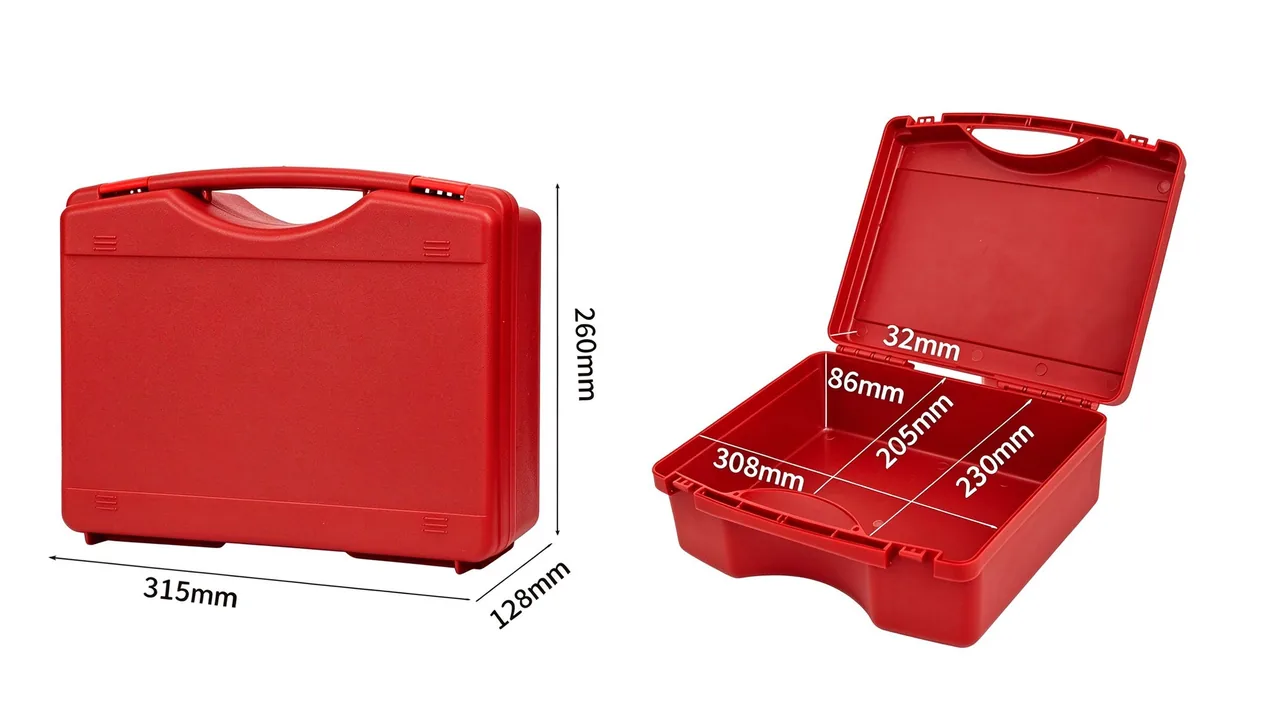
Putting a pile of tools into a box and putting a defined tool set into a box are two different engineering activities. The first only needs a cavity large enough. The second requires the container to remember where every item belongs, how many there should be, and in what order they are used, so that the operator can confirm completeness at a glance rather than by counting. A tool kit chest exists to solve that second problem. It is not a passive receptacle but an organisation system that fixes a tool list into geometry, and that distinction explains why the interior of a kit chest is considerably more elaborate than the interior of a general-purpose box of the same outer size, and why apparently trivial complaints such as "it does not fit" or "it will not go back in its place" appear after delivery.
At JUNZHJIA the working sequence for a kit project is fixed. Take the complete tool list and the usage scenario first; then decide chest form, tray count, locating method and sealing grade; and only then calculate mass and cost. The container is the carrier throughout; the real design object is the tool list and the operator's movements. This article covers the structure, liner, restraint, sealing, locking, stacking, inspection and procurement practice specific to this product family, and says nothing about the performance of the tools themselves. The thinking overlaps considerably with consolidated kit configuration, which is discussed in Weapons Consolidated Tool Kit Case: Modular Configuration of a CTK.
The Starting Point: A Defined Set, Not a Loose Load
Loose tool storage aims to fit everything in; set-based storage aims to place everything correctly. That difference shows up in three design choices. First, how space is divided: a loose-load box divides by volume and tries to fill it, while a kit chest divides by the tool list and reserves a fixed position for each item, preferring an empty slot to an opportunistic merger of two tools into one space. Second, locating precision: a loose-load box only requires that tools do not strike one another, while a kit chest requires every tool to return to its position after transport, with tolerable displacement measured in millimetres. Third, how completeness is verified: loose loads are counted, whereas kit chests rely on visibility, using an empty cavity to announce a missing item immediately.
Those differences drive both the cost structure and the failure modes. On cost, the liner and locating features take a much larger share, and the shell itself can often be simpler. On failure, the problems that appear are rarely broken shells; they are liners that do not match the measured tool outlines, locating features that surrender under vibration, and complete liner sets made obsolete when the tool list changes. Shifting the design object from volume to list is the first threshold a kit chest project has to cross.
List-Driven Layout: Translating a Tool Schedule into Space
The first step in list-driven design is to structure the tool schedule. A schedule usable for design carries five data fields: name and specification, outline dimensions including local protrusions, individual mass, vulnerable areas, and usage frequency. Without dimensions and mass the liner can only be estimated, and a poor fit after delivery is close to inevitable. Without usage frequency, zoning can only follow size, which puts high-frequency tools in awkward positions and soon persuades the operator to abandon the discipline of returning items to their places.
The second step is mapping the schedule onto space. The basic unit is a station: the block of interior volume occupied by one tool, comprising the tool envelope, the clearance a hand or a second tool needs during retrieval, and the wall thickness shared with the next station. Retrieval clearance is the field most often underestimated. In the pursuit of density, a station is sometimes cut as a snug replica of the tool, with the result that the item cannot be extracted by hand and has to be levered out with another tool, damaging both liner and tool. The practical rule is to reserve finger clearance in the direction of retrieval and to add a relief notch beside heavy items. The third step is fixing the number of layers and zones, which is decided together with the operator's movement pattern. For substantial tool lists, layering is almost unavoidable, and the layout methodology behind it is covered in How to Lay Out a Toolbox Interior: Multi-Layer Design That Maximises Usable Space.
Movement Pattern Decides Zoning: The One-Metre Rule
Interior layout ultimately serves movement. The rule most often quoted is the one-metre rule: standing at the task, the zone an operator can reach without conscious thought is roughly within one metre in front, between waist and shoulder height, and that zone should carry the highest-frequency tools. Positions outside it demand bending, turning or stepping, so they suit low-frequency tools and spares. The rule converts an abstract metric, usage frequency, into a physical location, and it is the most practical starting point for zoning.
Execution can follow three tiers. The first is the high-frequency tier, positioned in the top layer closest to the body once the lid is open, holding everyday hand tools and measuring instruments. The second is the medium-frequency tier elsewhere in the upper tray or in the middle layer, holding less frequent tools and consumables. The third is the low-frequency tier at the base or in corners, holding spares, specialist tools and heavy items that are rarely used. Switching between tiers depends on lifting trays out, so the upper trays should be removable as complete units and placeable flat beside the chest. That single detail determines whether the lower layer is ever actually used: if extracting a tray is awkward, operators end up crowding everything into the top layer regardless of the zoning plan.
Locating Methods: Slots, Magnets, Straps and Foam Cavities
The locating structure decides whether tools return to their positions after transport. Slot location uses formed cavities in the liner that mate with the tool outline; it locates accurately and costs moderately, and it suits tools of regular shape, with its performance limited by how closely the cavity follows the measured outline, since accumulated tolerance produces rattle. Magnetic retention suits small metal items and offers fast placement with a tidy visual result, but it does nothing for non-ferromagnetic tools and strong magnetic fields can disturb instruments and sensors, so the application has to be screened. Strap retention presses tools into fixed positions with elastic webbing; it adapts well, costs little and suits irregular loose items, but tension has to be re-checked periodically because aged webbing loses its grip.
Foam cavities sit between location and cushioning, cut on a CNC router to the outline so that they locate accurately and look orderly while also cushioning. Choosing among these methods turns on three variables: the regularity of the tool shapes, their mass, and the severity of transport. Regular shapes with hard transport favour slots or foam; irregular shapes of low mass favour straps; metal parts accessed frequently justify magnets, provided electromagnetic compatibility has been considered. Locating decisions sit inside the wider question of how a set is modularised, which is treated in Why Does a Toolbox Need Modular Internal Design?.
Anti-Scatter and Anti-Loss: Making Empty Slots Visible
One of the most valuable functions of a kit chest is that it makes absence visible. When every tool has a dedicated cavity, an empty slot means that item is not in the chest, and completeness can be judged without counting. Three conditions support that function: cavities map one-to-one to tools and cannot be substituted; partitions between stations prevent a tool from sliding into a neighbour's slot; and spares and consumables have defined positions of their own, so they cannot quietly occupy an empty slot.
Achieving this requires excluding two things at design stage. The first is the universal cavity shared by several tools; it adds flexibility but removes the ability to notice absence. The second is an unmarked accessory zone: cloths, cleaning fluid and tape, without fixed positions, end up wherever is most convenient, and that place is usually a slot that should have stayed empty. The practical answer is to define positions and capacity limits for accessories as well, and to provide a configuration card on the liner or the lid that maps tool names to positions. The card proves its worth during handover and audit, turning a count into a check against a chart.
Modular Trays: One Chest, Several Tool Lists
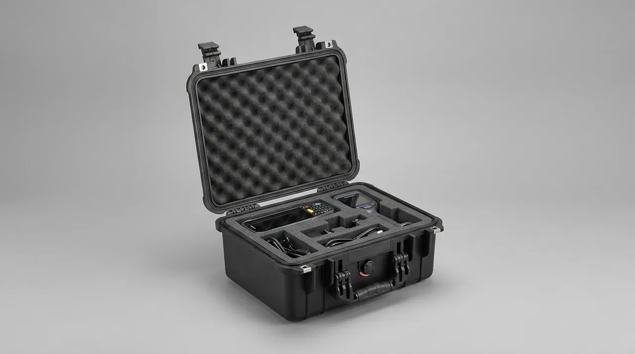
Within a single working system, the tool list is rarely single. Routine patrol uses one set, scheduled maintenance another, emergency response a third, while the chest itself could be common to all of them. Modular trays exist to resolve that conflict: the liner is divided into removable modules, each covering a functional group, and the operator assembles the modules needed for a task.
The benefits appear at three levels. On cost, the shell and lid are the most expensive parts, so reusing the chest substantially lowers the total investment across several configurations. On maintenance, a damaged or worn module can be replaced on its own instead of condemning the whole chest. On management, modules can be numbered, measured and inventoried separately, refining tool control from one box to a group of functions. The costs are equally real: locating and interlocking features between modules consume volume and add mass; poorly designed interfaces allow modules to shift and rattle in transit; and the inventory object count rises. Whether modularity pays depends on how often the list genuinely changes and how much sharing occurs. If three lists are always replaced as a whole, modular interfaces will not earn back their cost. Industry differences in how configurations are assembled are illustrated in Which Industries Suit a Trolley Toolbox?.
Dedicated Storage for Measuring Instruments
Every tool set includes a special class of member: gauges and instruments. They share a set of traits, being accurate, vulnerable to impact, sensitive to moisture and unhappy about rapid temperature change, with some needing state verification before and after use. Dedicating a zone to them is one of the marks that separates a kit chest from a general tool box. Four design requirements apply. First, a separate compartment: instruments should not share a chamber with hand tools that can strike them. Second, cushioning margin: beyond the locating cavity there should be a cushioning layer to absorb transport vibration and drop impact. Third, moisture control: instruments stored long-term need humidity managed, the liner material itself should not absorb water, and a desiccant pocket should be provided where needed. Fourth, visible status: calibration labels and certificates should face upward or outward so their validity dates can be checked at handover.
Instrument storage also ties into calibration cycle management. A useful practice is to bind the storage position to the calibration record, for example by labelling the cavity with an identification number and the next calibration date, and having the operator verify both before and after a job. The chest then carries part of the status management function rather than being purely physical containment. Protection principles for precision instruments are examined in How to Choose Protective Cases for Measuring Tools and Precision Instruments: Key Protection Points.
Centre of Gravity and Carry Balance in Heavy Kits
Kit chests generally weigh more than loose-load boxes of the same size, because of the liner and locating structure and because the list usually contains substantial metal. The extra mass affects carrying immediately, so mass management belongs in the design phase rather than being discovered when the prototype cannot be lifted comfortably. Three approaches help. First, control liner mass and structure: there is no need to use a high-density material across the whole area, and densities can be zoned by fragility so that dense material sits only where location and cushioning genuinely demand it. Second, layer by weight: heavy tools go to the base or close to the axle line, lighter tools into upper trays, which both lowers the centre of gravity and reduces the mass that has to be lifted out of the top layer. Third, decide the carry method early: a fully loaded kit chest often exceeds the comfortable range for one-handed carrying, so hand, shoulder or towed transport should be settled in advance and handles, straps or wheels specified accordingly.
Centre of gravity matters even more in towed configurations. A towed chest leans, and a high centre of gravity tips easily while stability during turns and over obstacles deteriorates. The heaviest tools should sit near the base and the axle line, and mass distribution through the depth of the chest should stay within sensible limits. The trade-off between mass and volume in hand-carried formats is examined in Portable Tool Box: Balancing Carry Weight and Capacity.
Sealing, Moisture Control and Rust Prevention
Because a kit chest contains many metal items, corrosion protection is not optional. Rust requires moisture, oxygen and an electrolyte, and at packaging level the countermeasures are to lower internal humidity and exclude corrosive media. Two approaches dominate. The first pairs desiccant with a sealed shell, isolating the interior behind a gasket and then absorbing residual moisture with desiccant, which suits long-term storage. The second uses vapour-phase corrosion inhibitor materials that release inhibitor molecules which adsorb onto metal surfaces and suppress the corrosion reaction, which suits complex assemblies that cannot easily be oiled item by item.
The two are frequently combined: the shell provides the sealing grade, while liners or accessories incorporate inhibitor film or foam, with a humidity indicator card for inspection. One caution is worth stating plainly. A high sealing grade does not automatically mean good corrosion protection, because a sealed chest can trap the moisture present at the time of packing, locking it in if no desiccant is used. The correct sequence is to control the humidity of the assembly environment, size the desiccant quantity to the liner volume, and fit an inspection window on the shell. Liner water uptake is another variable, and the comparison between materials is set out in How Should You Choose Toolbox Internal Foam?.
Locks, Tamper Seals and Accountability
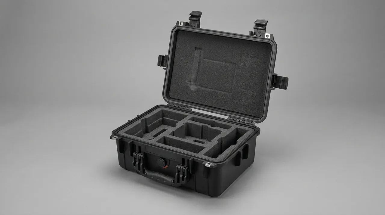
Kit chests often hold items of significant value, and the loss of a single piece can halt a task, so locking and accountability are core requirements rather than accessories. A lock must close reliably, open in a controlled way, and avoid degrading the seal. Common approaches include compression latches with padlock holes, built-in key cylinders, and integrated cylinder-and-latch designs. Selection involves trading opening speed against resistance to attack: field work demands quick access while high-risk settings demand stronger protection, and the two rarely coincide.
Tamper seals make handover visible. A single-use seal is recorded by number at issue, and the receiving party checks it intact before opening; a broken seal establishes that the chest was opened en route. Where traceability is required, the seal number should be filed together with the chest number and the tool list number. Design must provide a seal hole placed so that opening the chest necessarily destroys the seal, closing the loophole of an intact seal on an opened chest. One frequently overlooked constraint is that lock and seal hardware must not interfere with gasket compression: drilling through the joint to mount a hasp breaks sealing continuity directly, and the mounting surface has to be designed around the seal path.
Stacking, Lifting and Transfer Interfaces
A kit chest faces different conditions in storage and transfer than in use, and those deserve separate design attention. On stacking, the layered interior means a loaded lid tends to pass load into the trays and the tools beneath, so stacking load must be carried by the side walls and corner structure rather than by the lid. The way to achieve this is to provide a dedicated stacking shoulder at the top, separate from the sealing face, so that the weight of the chest above lands on structural columns. Layer count and load should be stated numerically in the technical requirement and verified by holding that load at the stated temperature and measuring lid deflection against gasket tolerance.
On lifting, a loaded kit chest is often heavy enough to need a sling or a forklift, so the shell should carry defined lifting points or fork channels with a rated load marked. Lifting points should be arranged so that the sling or sling line passes through the primary load-bearing structure and cannot pull the wall at an off-design angle. On transfer, the method of securing the chest in a vehicle should be planned, covering a high-friction base and side strap channels. For chests that move frequently between sites, stacking and lifting interfaces often affect daily experience more than the sealing grade does.
Inspection, Acceptance and Configuration Audit
Acceptance of a kit chest adds one core item to the normal routine: a configuration audit. A complete process has three groups. The first covers the shell: outer dimensions, wall thickness, integrity of structural parts, gasket contact and lock operation. The second covers the liner: cavity positions against the measured tools, integrity of partitions, and the placement and thickness of cushioning. The third is the configuration audit itself, loading and unloading every item on the list and recording whether retrieval is smooth, whether another tool is needed to assist, and whether any visible rattle appears once loaded.
The audit has to be carried out with the physical tools present; verifying against drawings alone proves nothing. Several quantities are worth recording during the audit: loaded mass, the practicality of one-handed or two-handed lifting, the proportion of interior space remaining after loading, and the time needed to retrieve each item. Those numbers serve both as acceptance evidence and as a baseline for later comparison when the list changes. For batch deliveries, a full audit on the first article and sampling on later batches works well, with sampling focused on liner tooling wear and any decay in locating accuracy. Where the chest has to work alongside cabinets and carts, interface design is covered in Tool Cart and Cabinet: Mobile Tool Workstation and Shop Storage.
Typical Failure Modes
Failures in kit chests cluster in four areas. The first is liner displacement, where tools stop returning to position after a period of use, usually because the liner was not positively fixed to the shell and migrated in transit, or because the liner material took a permanent set under load. The second is loss of location, visible as widening cavities and increasing rattle, generally caused by decaying resilience in foam or EVA and by dimensional change as the material stiffens in the cold. The third is latch and seal failure, showing up as loosening catches or moisture inside the chest, caused by non-adjustable engagement, aged gaskets, and joint penetration introduced when lock hardware was fitted.
The fourth is interference between modules, which is especially common in modular designs: a single module retrieves smoothly in the laboratory, but once several modules are installed, accumulated tolerance makes neighbours press against one another and extraction becomes difficult. Prevention is to reserve interface clearance between modules and to test retrieval with the full assembly installed rather than module by module. These four share one characteristic: most appear months after delivery and are hard to detect during acceptance, which is why a maintenance and inspection routine matters as much as the design itself.
Procurement Pitfalls
The first pitfall is an incomplete list. When the buyer supplies tool names without dimensions or mass, the supplier can only estimate, and a poor fit follows. The second is omitting usage frequency, which separates zoning from the operator's movement pattern, so the discipline of returning tools collapses within weeks. The third is making universal cavities the primary design, gaining flexibility while sacrificing the visibility of empty slots, which cancels the most valuable function of a kit chest. The fourth is over-designed modularity, spending heavily on module interfaces for a list that hardly changes, while adding tolerance accumulation and interference risk. The fifth is acceptance without a physical trial fit, so fit problems surface only after delivery when rework is expensive.
The way around these pitfalls is equally clear. Provide the full list and the usage scenario at enquiry, and state the carry method and stacking conditions explicitly. Ask for trial-fit records with the physical tools, not just liner drawings. Write the configuration audit and its quantities, including loaded mass, retrieval time and remaining space ratio, into the acceptance documentation. For lists likely to change, agree with the supplier in advance on the lead time and cost of liner modification. Settling these conditions before the contract leaves very little delivery risk in a kit chest project.
Frequently Asked Questions
Q: What fundamentally separates a tool kit chest from an ordinary tool box? A: The design object separates them. An ordinary tool box is designed around volume: the engineer maximises usable space within the outer dimensions, strengthens the structure, and improves opening and carrying. A kit chest is designed around a list: the engineer asks whether each tool has a fixed position, whether it returns there after transport, and whether its absence would be noticed at once. That difference propagates through every later decision. Space division shifts from filling volume to reserving per-item stations. Locating precision rises from merely preventing contact between tools to holding displacement within a few millimetres. Verification shifts from counting to visual judgement. The consequences show up in cost structure as well, since the liner and locating features take a much larger share of the total, while the shell can be simpler, and in failure modes, since the first problems to appear are fit and retention rather than shell strength. The most reliable way to judge whether a box is genuinely a kit design is therefore to look inside: dedicated stations for a defined list, partitions that prevent substitution, and configuration labelling tell the story better than the outer form or the material.
Q: How large is the difference between cutting a liner from drawings and cutting it from the actual tools? A: It is often large enough to decide whether a project has to be reworked. Drawings normally carry nominal tool dimensions, while the physical items have manufacturing tolerance, coating thickness, protrusions from handles and attachments, and variation between batches. Cutting to nominal dimensions can leave a cavity too tight on one side and too loose on the other. Too tight means the tool cannot be pulled out by hand and has to be levered with another tool, wearing the liner and damaging the tool. Too loose means the item moves continuously in transit, retention fails, and tools can strike each other. The practical approach is to measure or scan the physical tools, generate the cutting path from the measured outlines, and reserve finger clearance and relief notches in the retrieval direction. For batch projects, the tolerance band should be included as design input and checked against the worst-case combination rather than the average size. The trial fit cannot be skipped: the first article should be loaded and unloaded with the full physical kit, recording whether each item is smooth, whether it rattles, and whether any auxiliary action is needed. Those records become both acceptance evidence and the basis for adjusting the liner later.
Q: Is modular tray design suitable for every tool kit chest? A: No, and the benefit depends on how often the list changes and how much sharing occurs. Modularity pays most when one chest has to carry several substantially different lists, because the shell and lid are the costliest parts and reusing them lowers the total investment across configurations, while a damaged module can be replaced without scrapping the chest. When the list is essentially fixed and always replaced as a whole, the returns are limited and three costs appear instead. Module-to-module locating and interlocking features consume volume and add mass. A larger number of inventory items raises management complexity. Accumulated module tolerance can cause mutual interference once the assembly is installed, making retrieval difficult. A direct test settles the question: count how many times a year the list changes materially, and how often the same chest serves different lists. Frequent change with high sharing justifies modularity; infrequent change favours an integrated chest-and-liner design, with the budget spent on locating accuracy and sealing grade instead.
Q: What counts as acceptable storage for measuring instruments inside a kit chest? A: Four requirements define it. First, separate space: instruments should not share a chamber with hand tools or heavy items and should have their own compartment so they are not struck directly in transit. Second, cushioning margin: beyond the locating cavity there should be a cushioning layer to absorb vibration and drop energy, and for high-accuracy instruments the cavity surface should use a soft material that does not abrade. Third, moisture control: long-term instrument storage is humidity-sensitive, the liner should absorb as little water as possible, and a desiccant pocket with a humidity indicator should be provided, with vapour-phase inhibitor materials where appropriate. Fourth, visible status: calibration labels and certificates should sit where they can be checked at handover, ideally in a marked position giving the identification number and the next calibration date. One further point is frequently missed: retrieval should be mechanically simple, so that no contact occurs while the instrument is being taken out. Chamfers and guide features at the compartment mouth let the instrument slide along a defined direction instead of being angled into place by hand in a confined space.
Q: Does a kit chest need sealing and rust prevention? A: It needs both, and more so than a general tool box, because a kit contains many metal items of significant value and a single moisture event can affect several of them at once. Corrosion needs moisture, oxygen and an electrolyte together, and at packaging level the response is to reduce internal humidity and exclude corrosive media. Two approaches are common. Desiccant combined with a sealed shell isolates the interior behind a gasket and then absorbs residual moisture, which suits long-term storage. Vapour-phase corrosion inhibitor materials release molecules that adsorb onto metal surfaces and suppress the reaction, which suits complex assemblies that cannot be oiled item by item. The two are often used together, with a humidity indicator card for inspection. One point deserves emphasis: a high sealing grade does not automatically deliver good corrosion protection, because sealing damp air inside without desiccant traps the moisture and raises the risk. The right sequence is to control the humidity of the assembly environment, size the desiccant to the liner volume, and fit an easily read indicator window, then put the desiccant replacement interval into the maintenance routine.
Q: What should be considered when stacking kit chests? A: Stacking a kit chest differs from stacking a plain box because the interior is layered, and a loaded lid tends to pass load down into the upper tray and the tools below, which can compress the liner or damage contents. Stacking load must therefore be carried by the side walls and corner structure rather than by the lid. The key design feature is a dedicated stacking shoulder that lets the chest above land directly on structural columns or corner posts, kept separate from the sealing face and the lid surface. Layer count and per-layer load should be written into the technical requirement as numbers and verified by a compression test at the stated temperature and duration, measuring lid deflection and change in the sealing gap, then comparing against the gasket's compensation capacity. Temperature deserves attention beyond static load: polymer shells creep when held under load at elevated temperature, so a short room-temperature test does not guarantee that a chest will not sag in a hot warehouse. For chests that move frequently, lifting points and fork channels should be planned at the same time and marked with a rated load, so that nobody has to estimate safe lifting on site.
Q: How should accountability handover be designed for a kit chest? A: Three elements have to be present together: a lockable chest, a traceable seal, and a record bound to the tool list. On the chest, the lock should close reliably without compromising the seal, commonly a compression latch with a padlock hole or an integrated cylinder and latch. The trade-off is opening speed against resistance to forced entry, since field work wants quick access while high-risk settings want stronger protection, and the two rarely align, so the choice should follow the actual scenario. On the seal, single-use units recorded by number work best, and the seal hole must be positioned so that opening the chest necessarily breaks it; otherwise an intact seal can sit on a chest that has already been opened. On records, the seal number should be filed with the chest number and the tool list number to form a traceable chain. One easily forgotten detail is that drilling through the joint to mount lock hardware breaks sealing continuity, so lock and seal hardware must avoid the gasket path and be given a separate mounting boss where necessary.
Q: What should be reserved at purchase if the tool list may change later? A: The two things worth reserving are changeable space and a traceable baseline. On space, a proportion of the liner can be kept adjustable, filled with movable dividers or removable modules, so that a change is met by recombining rather than by remaking the entire liner. This differs from full custom cavity cutting: adjustability trades some density for flexibility, while full custom achieves maximum density at a high cost of change. The balance depends on how stable the list is expected to be. On baselines, the first-article acceptance should record the complete list, the liner drawings with measured dimensions, the loaded mass, per-item retrieval times and the remaining space ratio, producing a reference file for later comparison. When a change occurs, retesting against the same metrics shows whether the modification had side effects. It is also worth agreeing the lead time and cost structure for liner modification in advance, clarifying which changes need tooling modification and which only need recutting, so that the true cost and schedule do not come as a surprise when the list actually changes.