

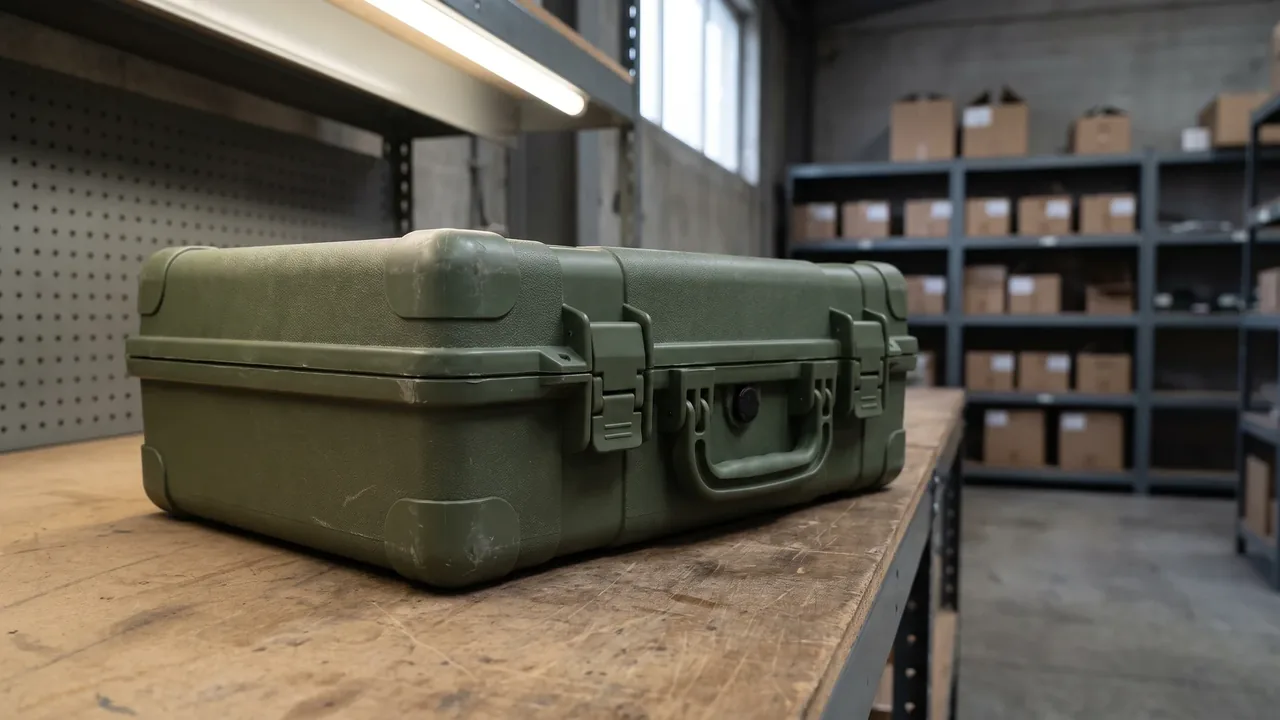
Within an equipment support system, a consolidated tool kit plays a very specific role. It gathers tools, gauges and specialised accessories that would otherwise live on separate schedules and recombines them, by task, into a single container unit that can be carried as a whole, handed over as a whole, and traced as a whole. That positioning places it on a different design path from an ordinary set-based tool chest. A set-based chest optimises storage around one fixed list; a consolidated tool kit manages configuration around a changing group of tasks. The first is measured by loading efficiency and access speed, the second by module combinability, configuration consistency and asset traceability, and that difference pushes the two products apart in many design decisions.
JUNZHJIA contributes to such projects at the container level, working on shell structure, trays and liners, module interfaces, sealing and corrosion protection, stacking and lifting, marking and inspection. One point must be stated at the outset: procurement and delivery involving military equipment remain subject to local regulations and export control requirements, and this article discusses packaging containers only. All test standards mentioned are cited as published environmental test methods and do not represent any certification conclusion. The organisational thinking overlaps with set-based tool storage, which is covered in Tool Kit Chest: Set-Based Organization Logic.
Defining the Consolidated Tool Kit and Its Boundaries
Three characteristics separate a consolidated tool kit from neighbouring concepts. The first is multiple sources: the tools it holds typically come from several independent groups, such as general hand tools, specialist assembly tools, gauges and inspection accessories, consumables and spares, each originally governed by its own numbering system, all brought into one container. The second is configurational variability: not every tool needs to deploy on every task, so the kit uses modularity to split contents into functional groups that are assembled as required. The third is traceable status: because the contents are valuable and a single missing item can halt a job, the kit usually carries a configuration record, identification markings and handover evidence.
Those three characteristics define the boundaries of the container design. Multiple sources require an interior that can accommodate items differing widely in shape, size and fragility. Variability requires interfaces that permit rapid assembly and replacement. Traceability requires the marking system to be integrated into the container structure rather than applied as an afterthought. Compared with these needs, simply increasing shell strength or sealing grade solves none of them, and that is why on consolidated kit projects the container engineer is usually brought in at the scheduling stage rather than handed a finished list to draw around.
The Three Layers of Modularity: Shell, Tray and Liner
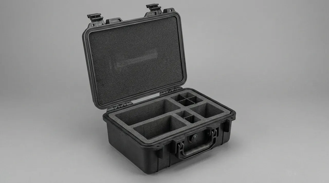
Modularity in a consolidated kit normally works in three layers. The first is the shell, the indivisible load-bearing body responsible for structural rigidity, sealing, locks, stacking and lifting interfaces, and all external marking. The second is the tray, a carrier unit that can be removed as a whole, each tray corresponding to one functional module and carrying its own locating features and handle so it can be moved and set down independently. The third is the liner inside the tray, which contacts the tools directly and provides per-item location and cushioning.
Layering matters because it isolates change at the right level. A small change to the tool list usually requires only a new liner. Redrawing the functional modules requires new trays. Only a change at the shell level, such as overall size, sealing grade or stacking load, forces a new structural design. That isolation lowers the cost of change considerably and allows one shell to serve several configurations. The price is space efficiency: every added structural layer consumes interfacial clearance, so the gap between tray and shell and between tray and liner must be tightly controlled, or the accumulation eats a significant share of usable volume. The general principles behind modular interiors are discussed in Why Does a Toolbox Need Modular Internal Design?.
Configuration Baseline and How a Tool List Becomes Modules
The first step in module planning is establishing a configuration baseline. A baseline is a frozen tool list containing, for each item, its name, identification number, outline dimensions, mass, fragility, usage frequency and functional group. The purpose of a baseline is not to forbid change but to give change a reference point. Once a baseline exists, any adjustment can be evaluated quantitatively: how much mass it adds, how much volume it consumes, and which module interfaces it affects.
The second step is module division. Three criteria are commonly used: by function, such as assembly, measurement, inspection and spares; by mission phase, such as preparation, execution and recovery; and by operator role. Divide too coarsely and a module becomes too large and heavy for one person to move. Divide too finely and the interface count multiplies while space is wasted on joints. The practical approach is to keep the loaded mass of a single tray within what one person can carry, and to balance module count against how often the task changes. Frequent variation justifies finer modules; stable tasks favour larger, more consolidated ones. When division is complete, a configuration matrix should be produced mapping every module to every task type, and it should form part of the delivered documentation.
Module Interfaces: Quick Release, Location and Anti-Misloading
The module interface is what distinguishes a consolidated kit from an ordinary set-based chest. A competent interface performs three functions at once: fast assembly and removal, precise location, and prevention of incorrect installation. Quick release is usually achieved with guide channels combined with catches or twist locks, so that no tools are needed to insert or remove a module. The number of actions should be as small as possible; in practice, one-handed completion within two steps is a sensible target, because field conditions may not allow the operator to set other items down. Precise location relies on guide features and locating faces that constrain all three axes and leave only one correct position once a module is seated.
Anti-misloading is the feature most often omitted and most worth including. When several modules look alike, an operator under pressure can easily seat one in the wrong bay, shifting the centre of gravity, making modules press against each other, and in the worst case preventing the lid from closing. Countermeasures include asymmetric guide features that physically prevent a wrong module from entering, mechanical coding through the spacing of locating pins, and prominent position numbers and colour coding on trays and shell. These can be combined for a modest cost increase and a large reduction in operator error. One caution: interfaces consume volume and add mass, so their bulk and weight must be counted in the overall budget rather than treated as free.
Liner Materials: EVA Cutting, Foam Cavities and Moulded Trays
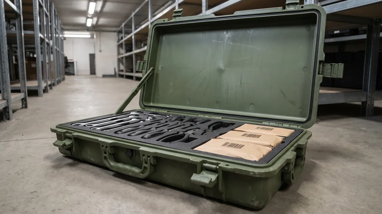
Liner material selection in a consolidated kit balances locating accuracy, cushioning and durability. EVA liners cut on a router follow the tool outline closely, locate accurately, look orderly and can be cleaned repeatedly, which suits regular shapes and instruments; their weaknesses are water uptake and declining compression recovery, since a cavity held under load gradually changes dimension unless the formulation and service conditions are controlled. Foam cavities use lower density to deliver better cushioning and suit base layers or fragile contents, but locate less positively than EVA and normally work in combination with a rigid tray.
Moulded trays are produced by rotational or injection moulding, so the tray is itself a structural part with cavities formed by the tooling. They offer the best durability, can be washed, and survive repeated loading without distortion, which suits modules used frequently over a long period; the drawbacks are tooling cost and the impossibility of modification when the tool list changes, so they suit highly stable configurations. In practice the three are combined: the moulded tray supplies structure and exterior form, EVA or foam supplies fine location and cushioning, and straps secure irregular items. Material selection should follow the actual fragility of the contents and the transport profile rather than a preference for density or price alone. General liner and cushioning practice is covered in Tool Cases: Hardware Tool Storage & Transport Protection.
Restraint against Shifting under Vibration
In transport a consolidated kit experiences sustained vibration with intermittent shock, and the most likely outcome is not breakage but gradual movement. Interfacial surfaces between tray and shell wear under repeated vibration, clearance grows, modules begin to shift slightly, tools slide within their cavities, and locating accuracy decays. The process is slow and typically appears months after delivery, which is why it is often attributed to misuse when the real cause is insufficient interface margin.
Three design measures suppress shifting. The first is pre-load: applying continuous normal force to a seated module so that contact is maintained throughout vibration, commonly through elastic strips, adjustable wedges, or compression features on the inside of the lid. The second is friction enhancement: texturing the interface or adding high-friction pads to raise the force needed for relative sliding. The third is travel limitation: fitting stops between module and shell so that even after wear the possible displacement stays within a few millimetres and cannot grow without limit. The three are usually combined, with pre-load the most important because it suppresses both vertical and horizontal movement. The correct way to verify restraint design is to measure module displacement after a vibration test, not to shake a module by hand in static conditions.
Sealing and Corrosion Protection
A consolidated kit holds many metal items and is often stored and moved in damp or rainy conditions, so sealing and corrosion protection have to be designed together. On sealing, the joint carries a continuous closed gasket compressed evenly around the perimeter by latches whose engagement can be adjusted, verified against an IP rating using the corresponding test method. Two details deserve attention. Pressure equalisation matters, because temperature swings and altitude change establish a differential between interior and exterior, and with no vent that differential bears on the gasket until opening becomes difficult. Equally, lock and marking hardware must not break sealing continuity, since any hole through the joint becomes a leak path.
On corrosion protection, the usual combination is vapour-phase corrosion inhibitor materials with a sealed shell and desiccant. Inhibitor materials release molecules that adsorb onto metal surfaces and are well suited to complex assemblies that cannot be oiled item by item, while desiccant absorbs residual moisture; the mechanisms differ and the two can be stacked. Two management points follow. Desiccant quantity must be sized to the liner volume, with the replacement interval written into the maintenance routine. Humidity indication should be easy to observe, ideally through a window in the shell so the internal state can be judged without opening. Sealing damp air inside without desiccant means the high sealing grade locks the moisture in, a common misconception worth stating clearly.
Stacking, Lifting and Field Transfer
Storage and transfer impose different conditions from use, and they need separate verification. On stacking, because the interior is layered, load applied to the lid passes through the trays into the tools, so stacking load must be carried by the side walls and corner structure. The method is a dedicated stacking shoulder at the top, separate from the sealing face, so that the weight of the case above lands directly on structural columns. Layer count and load should be written into the technical requirement as numbers and verified at the stated temperature and duration, measuring lid deflection and the change in the joint gap.
On lifting, a fully loaded kit usually exceeds manual handling limits, so the shell should provide lifting points or fork channels with a marked rated load, arranged so that the sling line passes through the primary structure and cannot tear the wall at an off-design angle. On field transfer, vehicle restraint has to be planned alongside short manual carries and obstacle crossing, covering handles and straps, a high-friction base, and optionally wheels. For equipment that moves frequently between sites, stacking and lifting interfaces often influence daily usability more than the sealing grade. Additional requirements for air transport are set out in What to Consider for a Protective Case in Air Transport, and stacking methods in Stackable Container: Stacking Strength and Space Efficiency.
Locks, Tamper Seals and the Accountability Chain
The management role of a consolidated kit requires locks and tamper seals to be part of the structure. Lock options include compression latches with padlock holes, built-in cylinders, and integrated cylinder-and-latch assemblies; the choice trades opening speed against resistance to forced entry, since field missions demand quick access while high-risk storage demands stronger protection. On seals, single-use units recorded by number should be filed with the case number and configuration number to form a traceable chain. The seal hole must be positioned so that opening the case necessarily destroys the seal; otherwise an intact seal can sit on a case that has already been opened.
A complete accountability chain also depends on configuration records. Delivery should include three documents: the case identification and serial number, the module and tray numbers, and the configuration list cross-referenced to tool numbers. The three reference one another by number, so any handover can be completed by checking seal condition against the configuration list. The structure should reserve space for this: a document pocket or card slot inside the lid prevents the configuration sheet from being lost in transit, and numbered areas on trays and liners keep markings legible. Lock, seal and marking hardware must all avoid the gasket compression path, and this deserves a dedicated check at the structural review stage.
Marking and Configuration Cards for Traceability
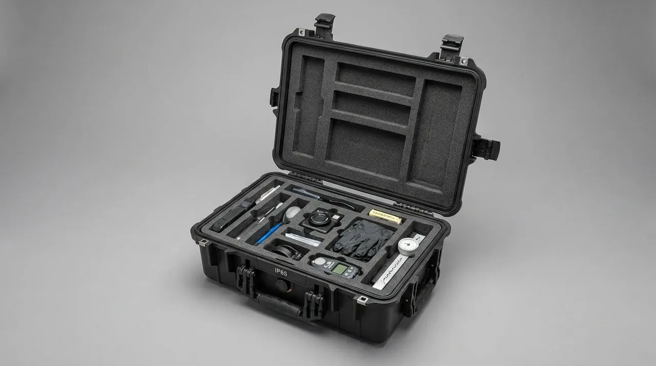
The marking system in a consolidated kit performs a navigation function. On opening the case, the operator needs to identify which tray serves which task, which cavity holds which item, and which items are not required this time, all without relying on memory. Three levels of marking are required: case level, tray level and station level. Case marking covers name, number, sealing grade and mass; tray marking covers module name, functional group and number; station marking covers tool name, number and specification. Font size and placement should match viewing distance, with the largest type at case level and the smallest but still legible type at station level.
Configuration cards complement the marking. A card lists the full configuration in schedule form with the location of each item, letting the operator verify completeness. Where the configuration varies, a replaceable card format works better, such as a slot-in sheet or a writable board, so that a change does not require a new case. Durability matters as much as content: printed labels rub away under repeated wiping and oil exposure, so in-mould marking, etching or durable labels are preferable. The corresponding acceptance step is to verify that markings agree with the actual contents, not merely that markings exist. Modular marking practice in mission-specific equipment is illustrated in Special Forces Case: Mission-Configured Modular Layout.
How to Cite Environmental Test Standards
Environmental suitability in a consolidated kit has to rest on testing, and the way standards are cited invites misunderstanding. Citing a published standard such as MIL-STD-810H means adopting the test procedures and conditions defined in that standard to reproduce specific environmental stresses, covering high temperature, low temperature, thermal shock, humidity, vibration, shock, rain and salt fog, in order to verify how the container structure behaves under those stresses. Citing a test method is not the same as holding a certification, nor does it imply any link to the qualification requirements of the equipment itself, and technical documents should say so plainly to avoid ambiguity in procurement discussions.
At container level, the tests worth scheduling include vibration to reproduce sustained transport stress and reveal whether module location and fasteners hold; shock or drop to verify impact resistance of shell and trays; thermal cycling to check the stability of dissimilar-material interfaces and the behaviour of the gasket; rain or immersion to verify the sealing grade; and salt fog to evaluate the corrosion protection of metal parts and inserts. Acceptance criteria should correspond to the design requirements, for example a maximum module displacement after vibration or retention of the sealing grade after drop, rather than a general statement that no abnormality occurred. For domestic projects, packaging and test requirements are commonly drawn from the GJB system, described in GJB Military Standard Cases: China Defense Compliance & Testing.
Inspection, Acceptance and Configuration Audit
Acceptance of a consolidated kit has three parts. The first covers the shell: outer dimensions, wall thickness, integrity of structural parts, gasket contact and compression uniformity, lock operation, and completeness of lifting points and stacking shoulders. The second covers modules: interface fit between tray and shell, quick-release action, displacement limits after seating, and agreement between liner cavities and the physical tools. The third is the configuration audit, loading and unloading every item against the configuration matrix, recording whether retrieval is smooth, whether auxiliary actions are needed, and whether visible movement remains after loading.
The audit must be performed with the physical tools present and must cover all module combinations rather than individual modules. Quantities worth recording include total loaded mass, individual tray mass, assembly and removal time per module, remaining space ratio after loading, and the time taken for a completeness check. For batch delivery, a full audit on the first article and sampling thereafter works well, with sampling focused on interface wear and decay in locating accuracy. The acceptance file should also include a marking and document check confirming that case number, module number and configuration list agree. Where the kit has to work alongside other equipment cases, selection and interface practice is covered in Military Protective Case Selection: Rifle Cases, Ammo Transport Cases & Individual Equipment Cases and Rotomolded Protective Cases: Rotational Molding Process, Double-Wall Structure & Load Capacity.
Failure Modes and Procurement Pitfalls
Failures in consolidated kits fall into five groups. The first is module misplacement, where a similarly shaped tray is seated in the wrong position, shifting the centre of gravity and obstructing closure; the cause is a missing anti-misloading feature. The second is module shifting, where a tray moves after vibration and tools then slide within their cavities, caused by insufficient pre-load or by wear removing any travel limit. The third is loss of liner location, visible as widening cavities and increasing rattle, caused by declining compression recovery in EVA or foam and by cold stiffening. The fourth is degraded sealing, evidenced by moisture or water inside, caused by aged gaskets, non-adjustable latch engagement, and joint penetration introduced when locks or markings were fitted. The fifth is divergence between marking and records, where case number, module number and configuration list disagree and configuration can no longer be audited, usually because no numbering system was established at delivery or because markings were not durable.
The pitfalls to avoid at purchase map one-to-one onto those failures. Do not freeze shell dimensions before the configuration is settled; allow the shell to accommodate change. Do not treat anti-misloading as optional, because misplacement probability in multi-module projects is not low under real conditions. Do not substitute static inspection for post-vibration measurement, since restraint must be quantified after testing. Do not write merely that the seal is good; state the IP rating and the test method. Do not treat marking and documentation as administrative matters to handle after delivery; reserve structural provision and select a durable process at design stage. Writing these requirements into the technical conditions and the acceptance file reduces delivery risk in a consolidated kit project substantially. General configuration practice for tool equipment cases appears in Hardware Toolboxes & Power/Manual/Repair Tool Boxes.
Frequently Asked Questions
Q: How does a consolidated tool kit differ from an ordinary set-based tool chest in its management objective? A: The two operate at different levels of management. An ordinary set-based chest manages whether one tool set is complete, and its verification actions revolve around quantity and position, using an empty cavity as the deciding evidence. A consolidated tool kit manages whether the configuration for a task is correct, which means answering a broader set of questions: which functional modules this task requires, whether those modules are all loaded, whether the loaded modules match the task requirement, and what has changed since the previous handover. The failure of the first is a missing item; the failure of the second may be a configuration error, where nothing is missing but the wrong module was carried and the task still cannot proceed. That difference propagates into structure. A consolidated kit must support rapid assembly and replacement of modules, must prevent similarly shaped modules from being seated incorrectly, and must carry configuration information with the container, whereas a set-based chest only needs locating accuracy for a fixed list. Deciding which design path a project should follow therefore begins with one question: is the object of management a fixed list or a changing set of tasks?
Q: Is anti-misloading really necessary, and does it cost too much? A: In multi-module projects the necessity is higher than most people expect. Field conditions are often tight, with gloves on and low light, and module shapes are frequently similar because the tool counts are close, so misplacement is not rare. The consequence is not merely a wrong position: the centre of gravity shifts away from its designed location, trays may press against one another so that tools cannot be extracted, and the lid may fail to close properly. Once such problems appear during a mission, the cost of resolution is far higher than the design-stage investment. The cost of anti-misloading is in fact controllable. Common measures include asymmetric guide features that physically prevent a wrong module from entering, mechanical coding through the spacing of locating pins or the position of a notch, and prominent numbers and colour coding on trays and shell. The first two involve tooling changes whose unit cost impact is limited after volume production, and the third adds almost nothing to structure cost. Leaving the problem to a written procedure relies on human attention, and its long-term effectiveness is usually poor.
Q: Modules shift after vibration. How should this be solved in the design? A: Three directions have to be addressed together, because any one alone has limited effect. First, pre-load: apply continuous normal force after seating so contact is maintained through vibration, using elastic strips, adjustable wedges or compression features on the lid inner face; pre-load is the most important of the three because it suppresses both vertical and horizontal movement. Second, friction: texture the interface or add high-friction pads to raise the force needed for relative sliding, which is particularly effective against horizontal displacement. Third, travel limitation: fit stops between module and shell so that possible movement stays within a few millimetres and cannot grow without limit as the interface wears. The combination has to be verified by testing. The correct check is to measure actual module displacement after a vibration test rather than pushing a module by hand in static conditions. Static checks reveal only excessive clearance and cannot assess stability under dynamic conditions, yet in service the problems invariably appear dynamically.
Q: Is a higher sealing grade always safer? A: Not necessarily, because the grade has to match how the container is used and maintained. Higher grades require greater gasket compression, more complex latches and more effort to open and close, and in frequent work an operator may fail to close it fully, producing a local failure. More importantly, a high sealing grade has no automatic connection to corrosion protection. If damp air is sealed inside at assembly without desiccant, the seal traps the moisture, internal humidity stays high for long periods, and metal parts face a higher corrosion risk than in a container with a lower grade. The right approach is to design sealing, desiccant and vapour-phase protection as one system: isolate the interior with the gasket, size the desiccant to the liner volume to absorb residual moisture, add inhibitor materials where appropriate, and provide an easily read humidity indicator. The maintenance routine should specify desiccant replacement intervals and inspection steps. At purchase it is worth confirming three things: the test method behind the stated sealing grade, whether a pressure equalisation valve is fitted, and whether provision exists for desiccant and humidity indication.
Q: How should environmental test standards be worded in technical documents? A: The key is to distinguish citing a test method from holding a certification, since the two are quite different in nature. Sound practice is to name the published standard and the specific procedures adopted, for example high temperature, low temperature, thermal shock, humidity, vibration, shock, rain and salt fog, and to state the test conditions, duration and acceptance criteria. What that wording means is that recognised methods are borrowed to reproduce environmental stress in order to verify container behaviour, not that the product holds any certification and not that it relates to the qualification requirements of the equipment itself. Technical documents should state this explicitly so it cannot be read as a certification claim. Acceptance criteria should also map one-to-one onto design requirements, such as a maximum module displacement after vibration, retention of the sealing grade after drop, or absence of significant corrosion on metal parts after salt fog, rather than a general statement that no abnormality was observed. Only when test items, conditions and criteria are all written down do results become comparable and usable as a consistency check across batch deliveries.
Q: What role does the configuration matrix play in a project? A: The configuration matrix maps modules against tasks and is the bridge between design and use. Its rows are modules, its columns are typical tasks or mission phases, and each intersection records whether that module is required for that task. The matrix works at three levels. At design level it converts operational need into structural input, tying module division directly to task frequency and preventing situations where one task needs most of the modules while others are almost never used. At production and delivery level it is the basis for liner machining and configuration audits, and the source of the numbering used in the marking system. At user level it lets the operator determine the load plan quickly before departure, reducing omissions and over-configuration that arise from judgement alone. The matrix should be managed as a controlled document with a defined change process: any adjustment to module division or task definition should update the matrix and trigger an assessment of the effect on shell structure, tray interfaces and marking. Without such a matrix, modularity tends to degrade into random combination, and completeness still has to be checked item by item.
Q: Where should mass control start in a consolidated tool kit? A: Mass control has to cover four areas. The first is the shell itself, the largest indivisible source of mass, which should be managed by structural optimisation rather than simple thinning: moving material from large flat panels into ribs and a skeleton, varying wall thickness by load distribution, and weighing stiffness against density in material selection. The second is trays and liners, an area easily underestimated, since a moulded tray is more durable but usually heavier than a thin liner combination, and the liner need not use high-density material throughout; density can be zoned by fragility so that dense material sits only where location and cushioning genuinely require it. The third is the distribution of tools and accessories, with heavy items placed near the base and the axle line both to lower the centre of gravity and to make heavy low-frequency items the first candidates for leaving behind when a configuration is trimmed. The fourth is interface hardware, since anti-misloading features, locating pins and catches are necessary but add mass, and their bulk and weight should be counted in the overall budget with the lightest workable implementation chosen. The objective is not minimum mass but a total that matches the intended carry method while satisfying protection and handling requirements.
Q: What must be written into the technical conditions when procuring a consolidated tool kit? A: Five groups at minimum. The first is configuration: the baseline list, the module division scheme and the configuration matrix, together with the treatment and cost structure for list changes. The second is structure: outer dimensions and internal clearances, wall thickness and material, structural hardware, interface requirements for quick release and anti-misloading, and displacement limits after modules are seated. The third is protection: sealing grade with its test method, pressure equalisation provision, corrosion protection scheme and desiccant arrangement, and the acceptance criteria for sealing tests. The fourth is load and transfer: stacking layer count and load with test conditions, rated lifting point loads, fork channel dimensions, and base restraint method. The fifth is marking and documentation: the content and process of three-level marking, the configuration card format, the numbering system, and the document list to accompany delivery. Once these five groups are specified, acceptance has a checkable basis and bidders without the relevant design and verification capability are filtered out at tender stage. It is worth repeating that procurement and delivery involving military equipment remain subject to local regulations and export control requirements, and this article addresses the technical conditions of the packaging container only.