


A top drive component case is difficult for reasons that have nothing to do with shell strength. A single shipment contains three mutually incompatible classes of sensitive surface: the main shaft splines and threads are assembly datum faces with zero contact tolerance, the guide rails and dolly tracks are metre-class long parts whose value is set by straightness rather than by strength, and the motor flanges and swivel transition interfaces rely on micrometre-level flatness and surface roughness to seal. Packing all of them into one stout generic crate almost always settles the account on site, in the form of misalignment during assembly, weeping interfaces, or rails that no longer meet straightness tolerance. The core conclusion is that a top drive case must be designed along four separate lines - zero-touch faces individually restrained, long parts supported at equal height on calculated spans, sealing faces protected by shape-matched covers instead of stacked material, and hydraulic plus electrical components isolated in their own clean, dry cavities - before a common structural and lifting system ties them together. Any approach that mixes these parts behind one universal liner simply defers the risk from the packing stage to the rig assembly stage, where rework costs an order of magnitude more.
This article addresses drilling equipment manufacturers, top drive overhaul shops, and oilfield equipment managers and buyers. The logistics chain for top drive parts is longer than for most industrial machinery. After dispatch the goods may sit in a warehouse, travel by road to a port, cross an ocean by container or fly as air freight, then move over desert or tidal-flat roads to the wellsite, spanning humidity, salt spray, dust and vibration along the way, with very few opportunities for intermediate inspection. In that chain, a single dent raised on a spline flank redistributes tooth load away from the design value and shows up later as fretting, abnormal temperature and cyclic torque fluctuation. A rail that yields plastically produces a non-uniform clearance between track and dolly over its whole length, making torque reaction transfer unpredictable while drilling. A nicked ring groove on a swivel interface becomes a high-pressure mud leak thousands of metres downhole. The sections below give packing parameters, liner zoning methods, corrosion and humidity targets, and arrival acceptance criteria that can be written directly into a purchase specification.
Contents
- Transport Environment and Case Boundaries for Top Drive Components
- Main Shaft and Splines: Identifying No-Touch Faces and Supporting Them
- Threads, Lock Nuts and Mating Tapers: Individual Containment
- Guide Rails and Dolly Tracks: Preventing Bending and Holding Straightness
- Rail Joints, Racks and Guide Rollers
- Motor and Drive Components: Fixation and Shaft Line Protection
- Swivel Interfaces and Sealing Faces: Flanges, Ring Grooves and Tapers
- Top Drive Hydraulics: Cleanliness Control and Port Capping
- Electrical and Sensor Components: Moisture, Vibration and Static
- Heavy Lifting, Saddles and Weight Distribution Inside the Case
- Corrosion Protection and Material Isolation for Sand and Wet H2S
- Liner Zoning, Sealing and Internal Humidity Management
- Marking, Inspection and Arrival Acceptance
- FAQ
- Conclusion and Further Reading
Transport Environment and Case Boundaries for Top Drive Components
Drawing the boundary between what goes into a case and what does not is the step that goes wrong most often on top drive projects. The main body frame, the lifting bail and links, an entire unsegmented rail, derrick-side mounting beams and large-diameter mud manifolds all exceed the capacity and lifting envelope of a normal component case. Forcing them inside drags both the tie-down system and the shell into a risk zone that cannot be verified. Six families genuinely need a dedicated component case: main shaft assemblies and torque transmission parts; rail sections, dolly tracks and travelling assemblies; AC variable-frequency motors with cooling accessories; swivel transition subs, gooseneck interface parts and matched seals; hydraulic power units, valve groups, cylinders and quick couplers; and electrical items such as drive modules, PLC racks, encoders and torque sensors.
Selection logic compresses into four rules. First, zone by no-touch face rather than by size. Put a splined shaft and a rack rail section in the same cavity and one shift during transport can drive a hardened tooth corner into another, producing a chipped tooth that cannot be repaired. Second, derive the support scheme from span, not from leftover space. A rail is accepted or rejected on overall straightness, so the number and position of support points must be calculated from the span, never back-fitted to whatever the crate happens to allow. Third, separate by cleanliness class and electrical rating. Hydraulic parts suffer from particles while electrical parts suffer from moisture and conductive dust, so their failure drivers point in opposite directions and they cannot share an atmosphere. Fourth, set corrosion protection from storage duration. The interval from dispatch to wellsite installation is commonly three to twelve months and may cross salt-laden coastlines and wide day-night temperature swings, so the protection scheme must be designed against the longest storage period rather than the nominal transit time.
| Component family | Dominant damage mode | Key protection requirement |
|---|---|---|
| --- | --- | --- |
| Main shaft and spline sleeve | Flank dents and chipped teeth, thread form damage, journal scoring | Spline and thread protectors, two-point journal support, axial restraint |
| Rail sections and tracks | Plastic bending over full length, track bore dents, rack tooth chipping | Multi-point equal-height support, open side inward, no stacking or bare sling contact |
| Travelling blocks and guide rollers | Roller rim crushing, bearing shock, pin bore deformation | One part per foam pocket, pins bagged separately |
| AC variable-frequency motor | Shaft extension keyway damage, encoder drift, winding moisture | Secured in running attitude, encoder end shielded, cavity humidity controlled |
| Swivel interfaces and seals | Ring groove dents, O-ring groove scoring, elastomer hardening | Blind cover over a soft pad, seals bagged and labelled by size |
| Hydraulic valves and cylinders | Particle ingress, internal rust, spool sticking | Dedicated clean cavity, O-ring port plugs, low-shedding liner |
| Electronic modules and sensors | Condensation, vibration fatigue, static discharge | Dissipative liner, humidity indicator, damper pads and shielded cable |
Treating this table as the skeleton of the packing list settles which part occupies which cavity and what each cavity must achieve while the quotation is still open, instead of forcing a liner design to be reverse-engineered at the end of production.
Main Shaft and Splines: Identifying No-Touch Faces and Supporting Them
The main shaft is the core of the top drive torque chain and the spline is the interface through which that torque passes to the lower connection. A spline transmits load on its flanks, so any raised plastic deformation there leaves only a few teeth sharing the load once assembled, driving contact stress beyond the design range and producing fretting, abnormal temperature rise and cyclic torque fluctuation in service. After case hardening or nitriding the flanks are hard but the edges are brittle, and one direct blow at a corner can chip a tooth. That class of damage is entirely preventable inside a case.
Four practices cover it. First, place the shaft horizontally with both ends supported at the bearing journals. Never let the middle span free and never use the splined section itself as a support point. For shafts with a high length-to-diameter ratio, use V-blocks or arc saddles matched to the journal diameter with a contact angle between 90 and 120 degrees and a soft facing on the contact surface. Second, fit a conforming protector over the whole splined section. Nylon, polyurethane or a metal sleeve with an elastomer lining all work, provided the bore clears the tooth tips by a small margin so that fitting the protector cannot itself score a flank. The protector must be axially locked on its outside diameter, otherwise it can slide off in transit and leave the spline bare again. Third, complete axial restraint before radial support. Fit limit blocks or straps on both sides of each saddle, because without axial restraint even a perfect saddle allows the shaft to slide until the spline end strikes a cavity wall. Fourth, when several shafts ship together, stack them in vertically aligned layers with continuous dunnage between layers, and never let an upper shaft rest on the journal or spline of the one below.
| No-touch face | Typical characteristic | Acceptable contact method | Explicitly prohibited practice |
|---|---|---|---|
| --- | --- | --- | --- |
| Spline flanks and tooth tips | Brittle hardened layer, stress sensitive | Outside diameter of a conforming protector | Timber or steel blocks touching the teeth |
| Shaft threads | Form damage drives torque shortfall | Thread protector over anti-rust grease | Tape wraps, cotton waste, bare wire slings |
| Bearing journals | IT6 to IT7 dimensional accuracy | Soft saddle with matching arc radius | Bare steel V-block contact |
| Mating tapers | High contact ratio requirement | Dedicated taper shield | Storing loose beside any hard part |
| Keys and keyways | Narrow load-bearing flanks | Bagged individually in a dedicated pocket | Mixed with fasteners in one bag |
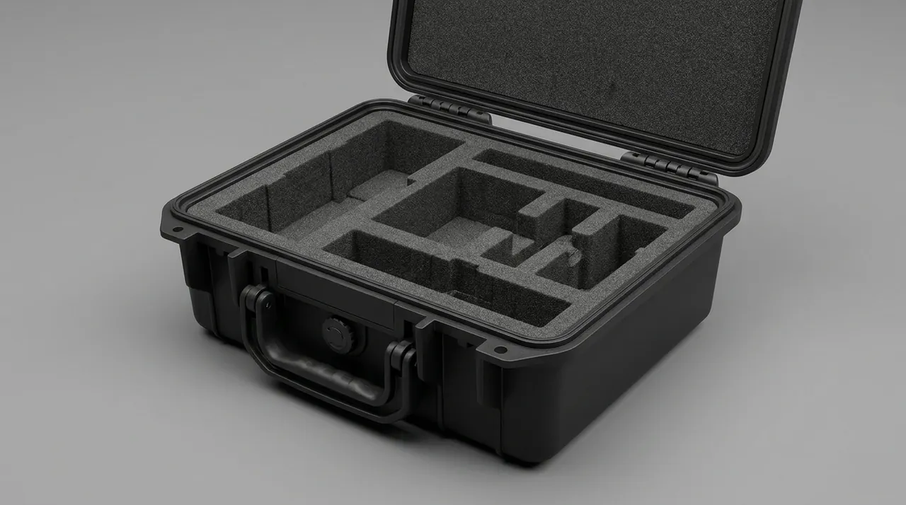
Main shaft assemblies are usually delivered together with couplings, spline sleeves and torque sensors, and the fit between these rotating parts is mutually dependent. Manage them as a set rather than as individual items, moulding one liner that presents them in installation order, so the crew can lift parts straight out of the case without searching. For comparable rotating and coupling assemblies, see Shaft Coupling Cases: Bore and Elastomer Element Protection.
Threads, Lock Nuts and Mating Tapers: Individual Containment
Threads appear in three places on top drive components: connection threads at the upper and lower ends of the main shaft, hydraulic fitting threads, and adjustment or lock threads. All share a small flank angle and a stress concentration at the root, so a single knocked-over burr is enough to push make-up torque away from specification. On site the usual test is nothing more than feel, which means a substandard thread can easily be installed.
Three points govern thread protector selection. First, match the specification and pitch. Engagement length should be at least 1.5 times the nominal diameter; a short sleeve pivots on its own rim under side impact and levers the end threads out of form. Second, do not standardise on a hard plastic moulding alone. Hard plastic turns brittle in low temperature, and fragments left in the thread root are worse than the dent they replaced. Prefer a composite protector with an elastomeric lining, or a metal sleeve with a polyurethane insert. Third, apply anti-rust grease before fitting the protector. The grease layer segregates moisture and damps micro-vibration at the same time. After fitting, confirm by hand that the protector turns freely; never use a cheater bar to force it on.
Lock nuts, tab washers, keys and keyway retaining plates get thrown into one bag far too often and then turn up on site under the wrong part number. Bag them by shaft serial number, mark the bag with the item number and installation location, and wrap keys and keyways in vapour phase paper before bagging. Mating tapers take a conforming shield with a non-woven lining, the purpose being to stop any hard particle from pressing a dent into the taper. A taper transmits torque through contact ratio, and a single dent visibly degrades the contact patch pattern.
Where a shaft has been dynamically balanced before dispatch, include the balance record and pin position markings in the case and leave a window in the liner through which the marks stay visible. That avoids moving the shaft repeatedly during arrival inspection and losing the correspondence between balance state and marking. Marking method also matters: marking directly on a mating face leaves a permanent trace, so keep any marking in non-mating areas or use a peelable coating.
Guide Rails and Dolly Tracks: Preventing Bending and Holding Straightness
Guide rails are the most counter-intuitive items in a top drive case. They look stout and forgiving, yet they carry an explicit straightness acceptance figure, and that figure is determined by self-weight deflection and support arrangement rather than by material strength. Support a metre-class rail at both ends with the middle span free and self-weight deflection alone can push overall straightness out of tolerance. Add road shock and the deflection moves from elastic to plastic, turning a part that passed final inspection into a rework item on arrival.
Support design means treating the rail as a beam rather than as filler in the crate. First, set the number of support points from the span, keeping spacing within 1.2 to 1.5 m and tightening to 1 m or less for unusually long sections. Second, level every support to the same datum within 2 mm, otherwise the rail is forced to conform to a curved support line under its own weight. Third, keep supports clear of joint faces and rack tooth sections. Local stiffness near a joint face is low, and a rack tooth face must never carry load at all. Fourth, orient the track opening inward or downward so that it cannot collect dust and so that the travelling block mounting surface is not exposed to falling objects.
| Rail section length | Suggested support points | Maximum spacing | Additional requirement |
|---|---|---|---|
| --- | --- | --- | --- |
| Up to 3 m | 3 | 1.5 m | End supports within 0.3 m of each end |
| 3 to 6 m | 5 | 1.4 m | Joint end shielded and separately restrained |
| 6 to 9 m | 7 | 1.3 m | Levelled supports, individual shims not to be swapped |
| Over 9 m | Sized at 1.2 m spacing | 1.2 m | Prefer two-section delivery with field splicing |
The prohibited practices belong in the specification as well. Never sling a rail with a bare wire rope. Contact points need corner protectors and soft pads, and the lifting points must sit where stiffness is high so that a web or an open section cannot buckle locally. Never stack rails on top of one another. Even with dunnage between layers, the upper weight passes through the dunnage as a concentrated load and leaves permanent bending during long storage. Never mix rails with large castings or forgings in one cavity, because the inertia of a heavy part under braking or a pothole will bow the rail. Never weld temporary lifting lugs onto a rail. The heat affected zone changes material properties and leaves a mark that cannot be removed.
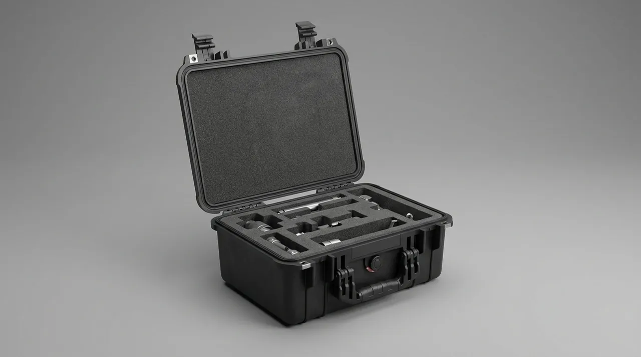
For rail sections travelling by sea, add lateral restraint inside the case so that roll cannot let the rail slide sideways in its cavity. Leave a 2 to 3 mm gap between restraint block and rail and interpose a soft pad, so the rail is constrained without being clamped; a permanent clamping force acting on a thin-wall section will eventually show.
Rail Joints, Racks and Guide Rollers
Adjacent rail sections meet at joint faces and locating pin bores, and the accuracy of that joint determines the straightness of the assembled track over its full length. Joint face flatness and pin bore fit both belong to the no-touch category, so shield the joint end as a unit, covering both the face and the bores with a cover that does not shed fibre. Bag locating pins and retaining plates as a set, and keep pin cylindrical surfaces away from other metal in the same bag.
The rack is the most fragile feature on a rail. Rack tooth contact fatigue life is tied directly to surface roughness, and any raised dent becomes a pitting initiation site. The workable method is a plastic tooth-shaped protective strip laid along the rack and clipped into position, matched to the actual tooth profile, held with ties that have a soft pad underneath. Do not simply lay thin film over a rack or wrap it in tape. Neither resists impact, and both leave adhesive residue that has to be scraped off during unpacking.
Travelling blocks, guide rollers and sliders form another group that needs one part per pocket. Roller rims are usually surface hardened and dent readily against hard objects, after which the assembly vibrates cyclically in service; roller bearings are rolling element structures whose raceways take axial shock directly. Mould closed-cell foam pockets that match each roller outline, one part per pocket, with the roller axis horizontal or in its running attitude and pocket depth covering at least 60 percent of the roller radius. Cover sliders and guide faces with a peelable protective film. Bag pins individually or hold them in a small dedicated pocket; a pin rolling loose inside a cavity will find the machined surface you least want it to touch.
Where a complete travelling assembly ships as a set, mount it on a pallet that can be lifted out as a unit, with forklift pockets underneath. The crew can then move the assembly with small equipment rather than handling it piece by piece, which removes manual handling risk at the source.
Motor and Drive Components: Fixation and Shaft Line Protection
Top drive AC variable-frequency motors are high-power machines, often with insulated bearings or an integral encoder, and they fail differently from mechanical parts. Mechanical damage concentrates at the shaft extension and keyway, while electrical degradation comes from moisture, condensation and vibration acting on winding insulation and encoder accuracy. The packing design has to cover both.
Three practices address the mechanical side. First, secure the motor in its running attitude, so that bearings see load in the same direction as in service rather than being carried in a non-design direction for months. A vertically mounted motor should stay vertical, or at least be supported in a way that reproduces the original mounting arrangement. Second, fit a shaft extension protector over the keyway and journal, and never use the protector's outside diameter as a load-bearing surface. Third, fill the space between mounting feet and cavity walls with EVA or XPE foam at slight interference, enough to prevent displacement under shock but not enough to distort the feet.
The electrical side turns on three items. Leads and terminal boxes are strapped and sleeved so no cable carries tension, with a moisture-resistant gasket under the box cover. Encoders and resolvers are precision devices whose mounting flange and shaft coupling must not see side load, so the encoder end faces upward or receives a dedicated shield. Winding moisture is controlled through cavity humidity, combining vapour phase corrosion inhibitor material with desiccant to hold relative humidity below 60 percent for the storage period, or below 40 percent where the specification demands it.
Motors connect to the main shaft through spline sleeves, gear couplings or disc couplings, all of which are matched sets that should occupy one cavity in assembly order. Where motor and shaft ship in different cavities, add cross-referencing marks to the case so that matched parts from different shipments are not mixed on site; mixing matched coupling parts on a top drive shows up immediately as eccentric torque transfer and additional shaft line load. For matched-set management of rotating parts, see Shaft Coupling Cases: Bore and Elastomer Element Protection.
Swivel Interfaces and Sealing Faces: Flanges, Ring Grooves and Tapers
Swivel transition subs and gooseneck interfaces are among the highest-pressure, most sealing-critical joints on a top drive. They normally seal through a metal-to-metal ring gasket or a taper with elastomer assistance, and performance depends on face flatness, surface roughness and the integrity of the ring groove. All three share one property: damage cannot be repaired on site. Once a ring groove is dented there is no field weld or lap that will restore it, and the part is replaced.
Packaging effort therefore concentrates on how the face is covered. First, fit a blind cover over the flange face and ring groove with a non-woven or soft gasket between cover and sealing face, tightening bolts in a symmetrical sequence so that one-sided over-torque cannot warp the face. Second, fit a conforming shield over taper interfaces with a soft lining and an axial locking feature so it cannot work loose. Third, bag seals individually and label size and material. O-rings, ring gaskets and metal seal rings should be packaged as sets keyed to the interface number. Seals intended for wet H2S service, such as hydrogenated nitrile or perfluoroelastomer, must be labelled clearly and never bagged together with ordinary nitrile items. Fourth, choose a mud-path rust preventive that is compatible with the fluid. Do not use an ordinary protective grease that contaminates the mud system; select a washable or drilling-fluid-compatible product and state the cleaning method in the delivery documents.
| Interface | Seal form | No-touch face | Protective measure |
|---|---|---|---|
| --- | --- | --- | --- |
| Swivel transition sub | Metal ring gasket | Ring groove and face flatness | Blind cover on non-woven pad, symmetrical tightening |
| Gooseneck interface | Taper contact | Taper contact ratio | Conforming shield with axial lock |
| Mud manifold flange | Elastomer ring gasket | Face roughness | Plastic end cap on soft pad, no tape |
| Hydraulic quick coupler | Flat or taper face | Sealing and guide faces | Dedicated dust cap, set numbered |
| Threaded connection | Thread with sealant | Thread form integrity | Thread protector over anti-rust grease |
A common misconception is that more wrapping is safer. Tape, thread sealant tape and cling film all age, leave residue and shed during long storage, so unpacking turns into a scraping job with a blade and creates a fresh damage source. The right direction is to replace stacked material with a shape-matched protective part that can be removed, reused and leaves nothing behind. For comparable high-pressure interface practice on wellhead equipment, see Wellhead Equipment Cases: Flange and Sealing Face Protection.
Top Drive Hydraulics: Cleanliness Control and Port Capping
The top drive hydraulic system drives backup tong clamping, internal blowout preventer operation, and rotating head and elevator control. Its valve groups are typically proportional or cartridge types with tight clearances that are highly sensitive to particulate contamination. Once hydraulic parts ingest particles in transit, the symptoms on site are spool sticking, sluggish response or pressure fluctuation, and diagnosis means dismantling stage by stage at a cost far above the packing investment.
Express cleanliness targets against ISO 4406. Common targets for top drive hydraulics sit around 18/16/13, with servo-class elements demanding more. The job of packing is not to improve the class but to prevent the as-built class from degrading during transport. Four measures apply. First, plug every opening that communicates with atmosphere. Use metal or nylon plugs with O-rings on ports, blind flanges with gaskets on flanged connections, and plastic caps crimped onto tube ends. Log plug quantities against the drawing and issue a plugging schedule with the case. Second, place valve groups in a dedicated clean cavity lined with a low-shedding closed-cell material. Do not use felt, cotton or hemp linings that shed fibre, and never put rusty carbon steel or uncleaned castings in the same cavity. Third, restrain hoses, accumulators and cylinders in their intended attitude. A hose must not sit below its minimum bend radius for months, and accumulators should have charging pressure recorded and be kept away from temperatures outside the permitted range. Fourth, re-inspect by sampling after transport in a clean environment, comparing particle counts with dispatch values to decide whether flushing is needed, rather than installing and relying on system flushing to fix it.
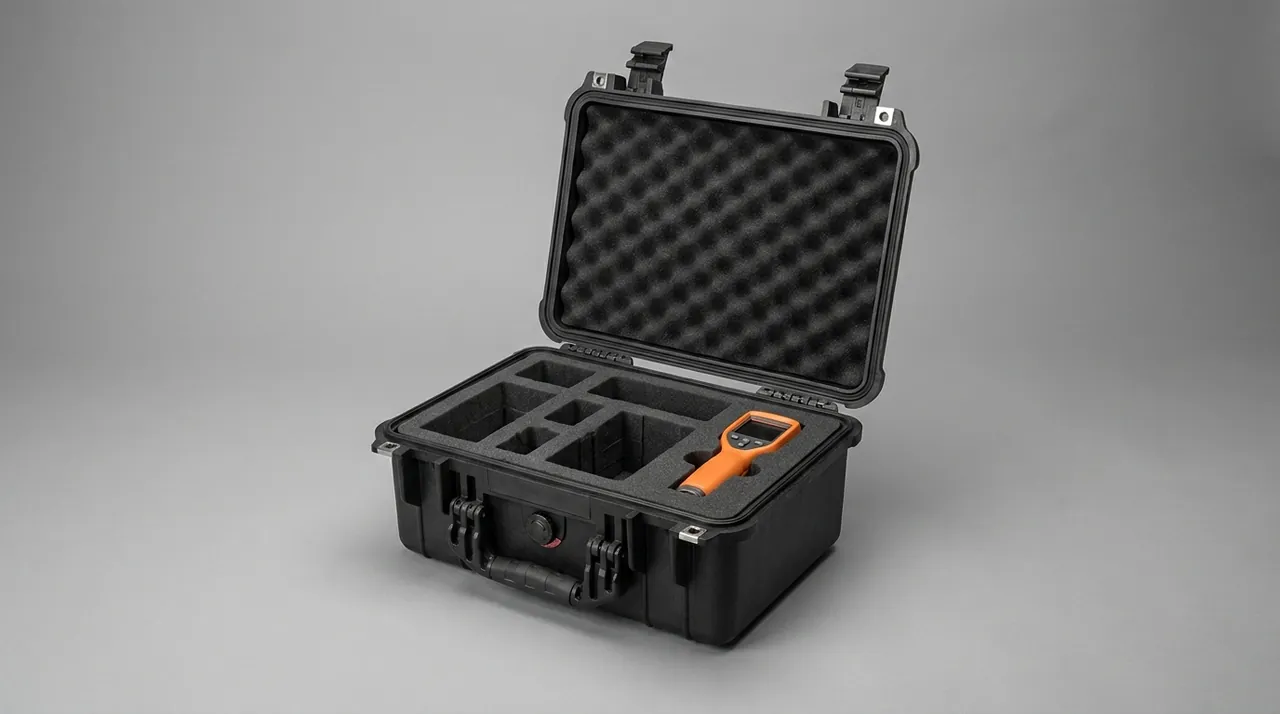
One conflict deserves explicit attention: cleanliness and rust prevention pull against each other. Heavy grease applied for corrosion protection becomes a contamination source at unpacking, while skipping protection for cleanliness leaves internal surfaces to rust after a condensation cycle. A practical middle path is a washable protective medium, or vapour phase protection in place of contact oiling, so that no anti-rust agent enters the fluid path. For cleanliness and capping practice on fluid ends exposed to high solids, see Frac Pump Cases: Fluid End and Plunger Protection.
Electrical and Sensor Components: Moisture, Vibration and Static
Top drive electrical items carry high value density and immediate consequences on failure. Drive modules, PLC racks, torque sensors, proximity switches and encoders exposed to moisture or vibration during transport often do not fail immediately; they produce intermittent faults weeks after commissioning, which are extremely hard to trace. Packing design cuts the three failure paths one by one.
Moisture control targets condensation driven by temperature cycling. Case internal temperature follows the day-night cycle, and moist air releases water at the low point of that cycle onto metal contacts and circuit boards. The method is humidity control plus an indicator: size molecular sieve or silica gel desiccant against net cavity volume, add a humidity indicator card, and read the card before opening the inner packaging. For modules facing long storage or transport across climate zones, use a composite inner pack of foil bag, desiccant and vapour phase corrosion inhibitor material to isolate the module from the case atmosphere.
Vibration control targets the structural fragility of sensing elements. Strain elements and signal conditioning circuits inside a torque sensor are shock sensitive, and proximity switches rely on a precise fit between sensing face and threaded housing. Cut pockets to each component outline and place one part per pocket, using closed-cell foam of moderate density so the part is neither clamped nor free to move. Fit damper pads between case and pallet to attenuate the high-frequency content coming up from the road. Relevant environmental test methods are described in the vibration and shock sections of MIL-STD-810H, cited here purely as test method references and not as a military certification.
Static control targets drive modules and boards containing MOS devices. Use a dissipative liner with surface resistivity in the 10^6 to 10^9 ohm range, place the module in a shielding bag before it goes into the pocket, and cap every cable connector. Personnel should wear a grounded wrist strap when unpacking, and should not touch connector pins directly in a dry environment. For dissipative liner and static-sensitive packaging configuration, see ESD Shield Cases: Protection for Static-Sensitive Components.
Heavy Lifting, Saddles and Weight Distribution Inside the Case
A top drive component case is often measured in tonnes, and the shell, the liner supports and the lifting interfaces form one system that must be designed together. The governing idea is to keep the load path continuous: from lifting point into the case frame, through the base and cross members, into the saddle, and into the component body. Break any link and the load concentrates locally and deforms something.
Six requirements cover it. First, mark centre of gravity and recommended lifting points on the case, and keep the angle between sling legs and vertical within 60 degrees; wider angles drive the horizontal component at the lifting point up sharply. Second, size rigging and shackles from total weight times a dynamic factor, taking the factor as 1.5 to 2.0 and higher for faster lifting acceleration. Third, design saddles from contact area and allowable material stress. A heavy part must not be carried on a few small points; calculate contact stress against the allowable for the material, and widen saddles for thin-wall cylindrical parts to spread load. Fourth, place heavy items near the case centre with the weight distribution as symmetrical as possible, so lifting does not tilt or twist the shell. Fifth, make interlayer load paths independent, with upper weight carried by posts or partitions straight to the case floor rather than through the parts below. Sixth, keep forklift and crane operations from interfering, placing forklift pockets clear of lifting points and internal supports.
| Component type | Typical unit weight | Load bearing method | Lifting requirement |
|---|---|---|---|
| --- | --- | --- | --- |
| Main shaft assembly | 1 to 8 t | Two arc saddles plus axial restraint | Slings with corner protection, no bare rope on journals |
| Rail section | 0.3 to 2 t | Multi-point equal-height support | Two or more lift points, balanced point for long parts |
| AC variable-frequency motor | 2 to 10 t | Mounting feet with rigid foam limit blocks | Lift in original attitude, never single-point on the shaft |
| Hydraulic unit and valve group | 0.5 to 3 t | Integral pallet over an anti-slip pad | Lift out as a unit, no piece-by-piece searching |
| Electrical cabinet | 0.3 to 1.5 t | Base support plus front anti-tip restraint | Never lift by panel face or handle |
During lifting a case experiences dynamic rather than static load, so the dynamic case should be the verification basis instead of multiplying static weight by a rule-of-thumb factor. Where a component genuinely cannot be carried safely inside a case, state clearly that it ships outside on a dedicated saddle and describe the split shipping arrangement in the delivery documents, so that no one on site misreads the scope of supply because a part is missing.
Corrosion Protection and Material Isolation for Sand and Wet H2S
Top drive components frequently end up in oil and gas fields with high sand content and wet H2S, and that environment changes two packing requirements: a higher corrosion class and stricter material isolation. Material selection for sour service belongs to product design and material compliance under the NACE MR0175 / ISO 15156 family; the role of packing is to preserve the condition of an already compliant component so that neither contamination nor corrosion during transport downgrades it.
Sand drives abrasive particle contamination. Grit reaching a track bore, a roller raceway, a hydraulic interface or a thread causes abrasive wear during assembly and operation. Three measures answer it: line cavities with low-shedding closed-cell material, avoiding felt, cotton and hemp; clean and cover every machined face and interface before packing, with thread protectors, port plugs and peelable film on track bores; and orient openings away from dust accumulation, with track openings inward or downward and all tube ends capped.
Wet H2S drives localised corrosion from surface contamination, and free iron contamination causing pitting in stainless steel is the most common case. Stainless and carbon steel parts must occupy physically separate cavities, separated by a continuous barrier rather than a local pad. Liner materials must not release chlorides, and tools or gloves that have touched carbon steel must not then touch stainless surfaces. Dissimilar metal mixing also raises galvanic corrosion, so aluminium against steel needs a non-metallic barrier, and where fastener and parent material differ, coating or an insulating washer separates them.
Corrosion class can be verified using the neutral salt spray method in GB/T 10125, taking hours to red rust as the basis for shell coating and hardware selection rather than judging by appearance. Vapour phase corrosion inhibitor material suits medium and long term storage of carbon steel, but compatibility differs for stainless, aluminium, copper and some zinc coatings, so check the compatibility statement to avoid discolouration caused by a reaction between the inhibitor and the coating. For protection of seals and wear parts in solids-laden service, see Mud Pump Cases: Liner and Valve Assembly Protection.
Liner Zoning, Sealing and Internal Humidity Management
The liner is the part of a top drive case that genuinely decides success or failure, and it carries three functions at once: location, cushioning and isolation. Location means the liner matches component outlines to single-part resolution and holds displacement in any direction to millimetres. Cushioning means the liner absorbs energy under shock instead of transmitting the peak. Isolation means the liner itself neither generates contamination nor reacts with the components.
On material selection, closed-cell EVA, XPE and polyurethane foam are the usual options, with density and hardness chosen from component weight and contact area: heavy parts take high density with low rebound, light precision parts take medium or low density with high rebound. Zoning follows three rules: hydraulics separate from electrics, stainless separate from carbon steel, and long parts separate from heavy parts. Partition walls between cavities should run continuously through the liner so that a shifted partition cannot connect two cavities in transit.
Sealing and pressure equalisation are a pair that must be satisfied together. Shell sealing comes from a gasket whose material follows the service temperature and media: silicone covers a wide temperature range but tears relatively easily, while EPDM weathers well but has limited oil resistance, so select against the actual environment. Where transport involves significant altitude change, air freight or multiple climate zones, a pressure differential builds across the shell, and a pressure equalisation valve lets gas move slowly in and out while blocking water and dust. A fully sealed case with no valve can have its gasket pushed open or its lid distorted by that differential. For valve selection logic, see Case Pressure Equalisation Valves: Principles and Selection.
Humidity targets should be graded by storage duration: below 60 percent relative humidity for short transit, below 45 percent for medium and long term storage, and below 40 percent for cavities holding electronic modules. Size desiccant from net cavity volume and target humidity with a safety margin, and place the indicator card where moisture reaches first, normally near the lid edge and the base, rather than tucked at the top. If the card has changed colour on arrival, inspect every metal part in that cavity for corrosion before releasing it to assembly. Hardware such as hinges, latches, handles and telescopic rods often determines the real service life of the shell in salt-laden air; for selection and maintenance guidance, see Toolbox Hinges, Latches and Seals.
Marking, Inspection and Arrival Acceptance
A marking system earns its place when someone on site can judge case condition and handling method without opening anything. Under GB/T 191 and GB/T 13384, the outside of the case should carry handling pictorial marks including this way up, keep dry, centre of gravity, lifting points and do not roll. A top drive case needs extra information: maximum single item weight, recommended lifting points, whether upright storage is required, and the location of the humidity indicator card that should be read first on opening. Item numbers should correspond to top drive installation positions, and ideally every part inside also carries both its item number and the installation node name, cutting drawing search time on site.
The packing list is the reference document for acceptance and should contain item number, description, quantity, unit weight, cavity location, no-touch face notes, matched fastener and seal list, plug count, desiccant quantity, dispatch cleanliness data for hydraulic items, and packing date. A mismatch between list and contents is the main source of arrival disputes, so have a second person independently verify the list once packing is finished.
Arrival acceptance is best run as six steps: check shell appearance and handling marks for signs of drop, puncture or water ingress; read and record the humidity indicator card; verify item counts and plug counts against the list; inspect no-touch faces, focusing on spline flanks, threads, sealing faces and ring grooves, rack teeth and roller rims; apply the agreed sampling plan, with a scheme such as the commonly used AQL approach written into the purchase documents, as described in Custom Case Acceptance: AQL Sampling Methods; and record and reseal, re-protecting any part opened but not yet installed and logging both opening and resealing times. For cleanliness-sensitive hydraulic items, unpack in a clean area, and if the line cannot be connected immediately, re-plug and record the time.
Test references should be named in the purchase specification: stacking and vibration tests under the GB/T 4857 and ISTA families, distribution cycle simulation under ASTM D4169, ingress protection expressed to IEC 60529 or GB/T 4208, and salt spray to GB/T 10125. One caution: test programme selection should follow the actual composition of the logistics chain rather than defaulting to the highest class, since the highest class buys cost without a matching reduction in risk.
FAQ
Q: Why can a splined main shaft not simply rest on a timber baulk or a steel block?
A: Load on a spline travels through the flanks, a narrow high-stress region, so a timber baulk makes line contact instead of area contact. The transient shock of lifting, landing or a rough road pushes stress near that contact line past yield and leaves a raised point that is very hard to see. Once assembled, only a few teeth share the load and fretting plus torque fluctuation appear quickly. Steel blocks are worse still: flanks are carburised or nitrided, giving high hardness with brittle edges, and impact against a hard object chips corners, which cannot be repaired. The correct approach is a conforming protector matched to the spline profile so its outside diameter carries support and restraint and impact is spread around the full circumference, combined with axial limit blocks at both ends of the splined section. If local conditions truly force timber support, restrict timber to the bearing journals or other non-critical areas, use moisture-controlled material, and add a non-absorbent, non-shedding pad between timber and journal.
Q: How should a thread protector be selected, and can tape be wrapped as a temporary substitute?
A: No, tape is not acceptable. Over long storage it ages, leaves adhesive residue and contaminates the thread root, so unpacking tends to involve scraping with a blade, which is itself a damage source. Tape also resists no side impact, so one knock rolls the crest over. Three points govern selection. The specification and pitch must match, with engagement of at least 1.5 times nominal diameter, because a short sleeve pivots on its rim and levers the end threads out of form. A hard plastic moulding alone is a poor choice, since it turns brittle in cold conditions and fragments left in the root are worse than the dent they replaced; prefer a composite with an elastomeric lining. Apply anti-rust grease before fitting, since the film segregates moisture and damps micro-vibration at once. After fitting, confirm by hand that the protector turns freely and never use a cheater bar. Taper and special-form threads need custom protectors rather than a generic sleeve forced on.
Q: How many support points does a long guide rail actually need inside a case?
A: The number is not a fixed value from experience; it should be back-calculated from span and straightness tolerance. Practice is to keep support spacing within 1.2 to 1.5 m, using at least three points for sections over 3 m, five to seven points for sections over 6 m, and 1.2 m spacing with a preference for sectional delivery above 9 m. Two conditions matter more than the count. Every support surface must be levelled to the same datum within 2 mm, otherwise the rail conforms to a curved support line under its own weight, and supports must stay clear of joint faces and rack teeth, because local stiffness near a joint is low and a rack tooth face must never carry load. Keep end supports within about 0.3 m of each end so the overhanging tip does not deflect excessively when lifted. Once the support scheme is fixed, run a deflection check against the transport dynamic factor and compare the worst case with the straightness allowance, rather than confirming appearance under static conditions alone.
Q: Can a top drive guide rail be shipped as a single unsegmented piece in a case?
A: In most cases this is not advisable and often not feasible. A full-length rail usually exceeds the loading envelope and lifting capacity of a standard component case, and even if it fits, the way the case is loaded, stacked and lifted becomes very hard to verify, pulling the tie-down system and the shell into a risk zone together. A more practical route is sectional delivery with field splicing: split into 3 to 9 m sections, each shipped in its own case or on a dedicated saddle with a protective cover, joint faces shielded with locating pin bores protected, and the shipment accompanied by splicing instructions and a tool list. Where a project genuinely requires unsegmented transport, treat the rail as an independent transport object on dedicated saddles with multi-point tying and a full protective cover rather than forcing it into a component case, and still provide multi-point equal-height support and no-touch face protection with a separately verified lifting plan. Either way, list the no-touch faces and support requirements in the purchase documents and require the supplier to respond line by line in the packing plan.
Q: Can hydraulic ports be plugged temporarily with cotton waste or paper?
A: Not recommended, and on cleanliness-critical projects it should be explicitly prohibited. Cotton waste sheds fibre, and fibre entering a valve body gathers at an orifice and produces abnormal flow and spool sticking. Paper absorbs moisture and creates a local rust source on the port wall, and on unpacking the rust travels into the system with the oil. Both types of contamination cost far more to trace than the plug itself and typically surface only at commissioning. The correct approach is metal or nylon plugs with O-rings on ports, blind flanges with gaskets on flanged connections, and plastic caps crimped onto tube ends. Log plug quantities against the drawing, list them in the delivery documents and verify completeness on arrival. Where temporary protection is unavoidable in transit, use a purpose-made elastomer sealing cap rather than wrapping threads in ordinary tape. Unpack in a clean, wind-free, dust-free area, and if the line cannot be connected immediately, re-plug the opening and record the time it was opened.
Q: What liner should be used for electronic components, and what surface resistance is appropriate?
A: Electrostatic-sensitive electronic modules call for a dissipative liner, typically with surface resistivity between 10^6 and 10^9 ohm. The range matters in both directions. Below it, a conductive liner creates a fast discharge path from module pins to liner and can cause damage through a momentary high current. Above it, an insulating liner cannot bleed the static charge that accumulates in transit and during unpacking, so discharge at the moment of contact can still puncture a gate oxide layer. Beyond the liner, place each module in a shielding bag before it goes into its pocket and cap every connector. Dry conditions raise static accumulation considerably, so in low-humidity regions or winter operations, staff should wear a grounded wrist strap and avoid touching connector pins by hand. Liner resistance also shifts with humidity and contamination; grease or dust on the surface degrades dissipative performance, so ask the supplier for the test method and a note on how resistance varies with humidity rather than accepting a single nominal figure.
Q: What extra steps are required for components intended for wet H2S service?
A: Start by being clear about scope. Selection of sour-service material, hardness limits and heat treatment condition belong to product design and material compliance under the NACE MR0175 / ISO 15156 family. Packing does not change material compliance; it preserves the condition of the chosen material so that transport does not downgrade it. Three packing steps then follow. First, zone pressure-containing parts, seals and fasteners that will see wet H2S into their own cavities, bag seals by material and label them, so that hydrogenated nitrile and perfluoroelastomer items are never mixed with ordinary nitrile in one bag. Second, physically separate stainless from carbon steel, using a continuous barrier rather than a local pad, to prevent free iron contamination from causing pitting; tools and gloves that have touched carbon steel must not touch stainless surfaces afterwards. Third, control and record cavity humidity, since condensation is a recognised contributor to sulphide stress cracking; hold medium and long term storage cavities below 45 percent relative humidity and fit a humidity indicator card. Where aluminium and steel ship together, add a non-metallic barrier to suppress galvanic corrosion.
Q: Which items should a factory acceptance check cover on a top drive component case?
A: Run it as a fixed six-step routine. First, inspect shell appearance and handling marks for any sign of drop, puncture or water ingress, and confirm the marks are complete; a top drive case should also state maximum single item weight, recommended lifting points and whether upright storage is required. Second, read and record the humidity indicator card, and if it has changed colour inspect every metal part in that cavity after opening. Third, verify item counts and plug counts against the packing list, since a missing plug means an opening was exposed in transit. Fourth, inspect no-touch faces: spline flanks, shaft threads, sealing faces and ring grooves, rack teeth and joint faces, roller rims. Work on a clean bench to avoid secondary contamination. Fifth, apply the agreed sampling plan, with sample size, inspection items and acceptance criteria written into the purchase documents using a recognised AQL approach. Sixth, record and reseal, re-protecting any opened but uninstalled part and logging opening and resealing times.
Conclusion and Further Reading
Four rules summarise the scheme: restrain every no-touch face individually, support long parts at equal height on calculated spans, cover sealing faces with shape-matched protection, and give hydraulics and electrics separate humidity-controlled cavities. JUNZHIJIA builds top drive cases with zoned liners, matched seals per model and custom saddles for OEM supply.
Related Reading