

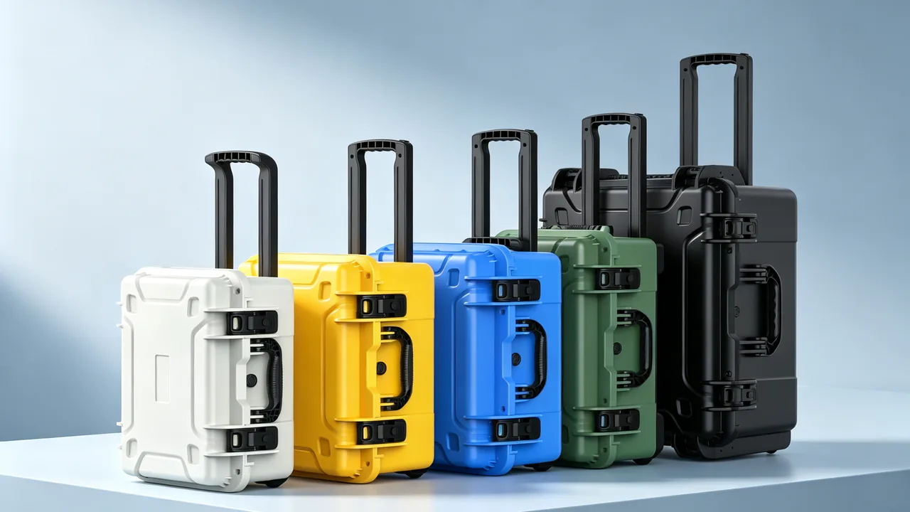
Frac pumps are the core equipment of shale and tight-formation stimulation, and the triplex or quintuplex plunger pumps used on location push sand-laden fracturing fluid downhole at discharge pressures of 70 to 105 MPa. The fluid end block, valve assemblies, plungers and packing see high-velocity abrasive erosion, alternating pressure and assembly stress, which makes them the most expensive and most frequently replaced component group on the pump. Most of these parts are machined from a single alloy-steel forging, a fluid end block often weighs 1.5 to 4 tonnes, a plunger carries a ceramic spray coating or hard chrome layer, and the tolerances on valve seat tapers and plunger outside diameters are commonly held in the 0.02 to 0.05 mm range, while the distance between the wellsite and the spare-parts warehouse can span thousands of kilometres of road and ocean freight. JUNZHIJIA holds that transport protection for frac pump fluid end parts cannot follow the uniform-cushion logic of a generic equipment case; instead the heavy lifting of the block, the no-scratch rule for plated plungers, the no-contact rule for sealing tapers and the hydrogen cracking risk of wet sour service must be treated as four separate engineering problems, answered respectively by load-bearing structure, non-contact location, taper guards and vapour-phase corrosion protection. This article works from failure mechanisms and sets out packaging structures, liner selection, lifting rules and acceptance points for the whole journey from factory dispatch to spare-parts turnaround and overseas project delivery.
Spare parts that are declared scrap on arrival at the wellsite are usually ruined in steps that look trivial at the time. If a fluid end block is lifted on two slings set at an angle, the case side panels deflect under the eccentric load and that deflection passes through the bottom padding into the valve seat taper, leaving no visible mark yet producing a leak at 90 MPa after installation. A plunger that slides a few centimetres inside the case can strike a neighbouring valve body and chip its ceramic coating, and no amount of hardness makes that coating repairable in the field. Packing rings and rubber O-rings already face chemical attack from hydrogen sulphide and condensate on location, and if the journey adds a hot deck followed by a humid ocean crossing, hardening and permanent set appear before the parts ever reach the pump. The most hidden risk is mixing: fluid end blocks of different pressure ratings and plungers of different diameters shipped in the same case cannot be told apart by eye, and a wrong installation can trigger cascading damage through the whole fluid end. This article is written for frac equipment buyers and for the spare-parts logistics and warehouse teams of completion service companies.
Transport Damage Profile of Frac Pump Fluid End Parts
A frac pump is a positive-displacement plunger pump with a high-pressure, high-rate, high-proppant duty cycle. Its fluid end carries one load spectrum in service and an entirely different one in transit, so protection design must begin by separating the two. In service, the fracturing fluid is water plus friction reducer, crosslinker and proppant, the proppant being 20/40 or 40/70 mesh quartz sand or ceramic beads at concentrations that field practice can push to 1 to 8 ppa, roughly 120 to 960 kg per cubic metre depending on the well, and the resulting jet through the valve gap produces severe erosion. Pressure alternates between suction and discharge hundreds of times a minute, so valve seats and block bores take repeated impact and micro-motion. Well fluids frequently carry hydrogen sulphide, carbon dioxide and chlorides, which together form a wet sour environment. In transit the loads become low-frequency high-amplitude shock, sustained vibration, static stacking compression, temperature and humidity cycling, and marine salt spray. These four transport loads damage parts in ways that no single cushion thickness can address.
Arrival inspection statistics place transport damage to the frac fluid end in four groups. The first is distortion of mating faces: a block is heavy with an offset centre of gravity, and if the case has no rigid load structure the bending moment of lifting and turning is transferred through padding into the valve seat taper and block end face, producing an ovality that cannot be seen and that fails under pressure after installation. The second is mechanical damage to coatings: the ceramic spray or hard chrome layer on a plunger is hard but brittle, so contact with a metal part or case wall instantly produces chipping, flaking or scoring, and a damaged coating cannot be repaired, only the whole plunger replaced. The third is impact damage to tapers and threads: valve seat tapers, metal seal faces on discharge flanges, stay rod threads and bolt threads all lose their sealing or preload function after a single dent or rust pit. The fourth is elastomer ageing and metal corrosion: packing, O-rings and polyurethane valve inserts are sensitive to ozone, ultraviolet light, oil and humidity cycling, while block bores and fasteners suffer pitting in salt spray.
Protection structure follows from knowing exactly which surface must be preserved. The critical faces on a frac fluid end are normally the block bore and end face flatness, the valve seat mating taper, the plunger outside diameter where surface roughness is commonly held to no more than Ra 0.4 micron and diameter tolerance is typically around plus or minus 0.013 mm, the metal seal face and ring groove of the discharge flange, and the threads of stay rods and bolts. The table below maps components to materials, precision faces, transport risks and the main protection route, so that a buyer can check the plan row by row.
| Component | Typical material | Critical precision or mating face | Main transport risk | Protection route |
|---|---|---|---|---|
| --- | --- | --- | --- | --- |
| Fluid end block | Alloy steel forging, 4130 or 4330 modified class | Bore, end face flatness, seat bore taper | Lifting moment causes ovality, salt spray pitting | Steel skeleton tray, leg load distribution, sealed rust protection |
| Valve seat | Carburised or nitrided alloy steel, hardfaced insert | Outer taper and block seat bore taper | Chipping, scoring and rust on taper | Non-contact location, taper guard, separate compartment |
| Plunger | Stainless base with ceramic spray or hard chrome | Outside diameter roughness and tolerance | Coating chip, flake, score | Full soft wrap, end caps, no stacking |
| Packing and seals | Aramid or PTFE braid, NBR, FKM, polyurethane | Lip and sealing faces | Hardening, permanent set, swelling | Dark, cool storage, desiccant, separate sub-case |
| Discharge manifold and flanges | Alloy steel forging | Metal ring groove, flange face | Groove chipping, thread damage | Face cover plate, thread plug, rust paper |
| Stay rods and fasteners | High-strength alloy steel | Threads, bearing shoulder faces | Thread bruising, corrosion of hydrogen-sensitive steel | Thread sleeves, compartmentalised fixture, VCI wrap |
The tolerances and roughness values in the table are typical industry ranges, and the governing figures are always those on the drawing and specification of the specific pump model. During scheme review JUNZHIJIA asks the customer for drawings or a 3D scan of the physical part, marks every precision face on the model, and then allocates cushion layers, location blocks and guards to match, instead of wrapping the whole part in one block of foam. The general method is described in the custom foam inserts guide.
Fluid End Block: Lifting and Load Path for Monoblock and Three-Piece Designs
The fluid end block is the structural body of the pump and sets both flow rate and pressure rating. There are broadly two architectures. A monoblock integrates suction manifold, discharge manifold and all plunger bores into one large forging, which gives high stiffness, few sealing points and a concentrated mass. A three-piece design uses a fluid end body with separate suction and discharge manifolds clamped by stay rods, which is easier to service and splits the mass across components. The two architectures pose different packaging problems. A monoblock can weigh 2 to 4 tonnes with a strongly offset centre of gravity that is hard to judge by eye, so case load bearing is the dominant issue. A three-piece set must ship together with its rods, seals and spacers, so keeping the matched sets intact and preventing cross-mixing becomes the dominant issue.
The first source of transport damage is lifting. Heavy parts of this class are loaded and unloaded at the wellsite and at the port with a crane and slings, and if the case does not show the centre of gravity and the lift points, an operator will naturally set a single sling at an angle. The case frame then twists slightly under the eccentric load, and the twist is amplified through the bottom padding into the block, shifting end face flatness and seat bore taper by micrometres. That distortion can barely be detected by eye on arrival, yet it shows up as a slow weep during pressure testing. JUNZHIJIA embeds a steel load tray or aluminium profile skeleton in the case floor so that block weight travels through four corner legs into the outer frame instead of through cushion foam; the foam then only damps vibration and protects surfaces rather than carrying static load. Built this way, the case should show no visible permanent set at 1.5 times rated load. Bearing capacity and shock absorption are independent metrics, a point already made in the logic of shock and seal transport cases: a heavy-part case should prioritise static compression resistance with impact as a secondary function.
The second source is in-case displacement. A block usually offers only a few flat surfaces suitable for support, with the rest being curved walls and port bosses, so flat pads give line contact along two or three edges, gradually crushing the foam under vibration and opening a path for movement. The correct approach takes three or four load points on non-precision surfaces such as the outer sides and unmachined base, using CNC-carved hard location blocks contoured to the casting or forging shape so contact becomes an area rather than a line. Precision surfaces, meaning seat bore tapers, end faces and flange faces, stay clear of everything with a gap of at least 10 mm maintained around them. Location block hardness must be lower than the block itself to avoid reverse scoring.
The third source is stacking. Overseas projects often ship by the container load with several spare sets stacked, so lower cases carry the static weight above them. Rate the stacking load against unit mass with a 1.5 safety factor, fit metal stacking corners at the four case top corners so upper cases bear on the outer frame rather than the centre of the lid, and mark no-standing and maximum stack height on the lid. For assemblies over three metres, or sets with cantilevered manifolds, use a split lid or a top loading port together with an overhead crane and external guide slings so that nothing is levered inside the case. Three-piece sets also need matched compartmentation inside: body and the two manifolds each occupy their own cavity, stay rods are bundled in groups by drawing number, and seals and spacers go into labelled sub-bags carrying the matching set number so that rods and gaskets from different pump models never mix.
Valve Seat Tapers and Sealing Faces: No-Contact Rule and Guard Design
Wherever a metal-to-metal seal depends on a taper, the tolerance for impact is effectively zero. The valve seat in a frac pump normally seats in the block bore on a small-angle self-locking taper, commonly in the 1:4 to 1:6 range as a typical figure that must be confirmed against the drawing. The engagement length is short and the contact stress is high, so any dent, burr or rust pit on the taper becomes a leak path at high pressure, and the leaking abrasive fluid then enlarges the defect quickly, producing the classic chain from pitting to washout. There is therefore only one governing rule for transporting valve seats: the taper must never touch anything.
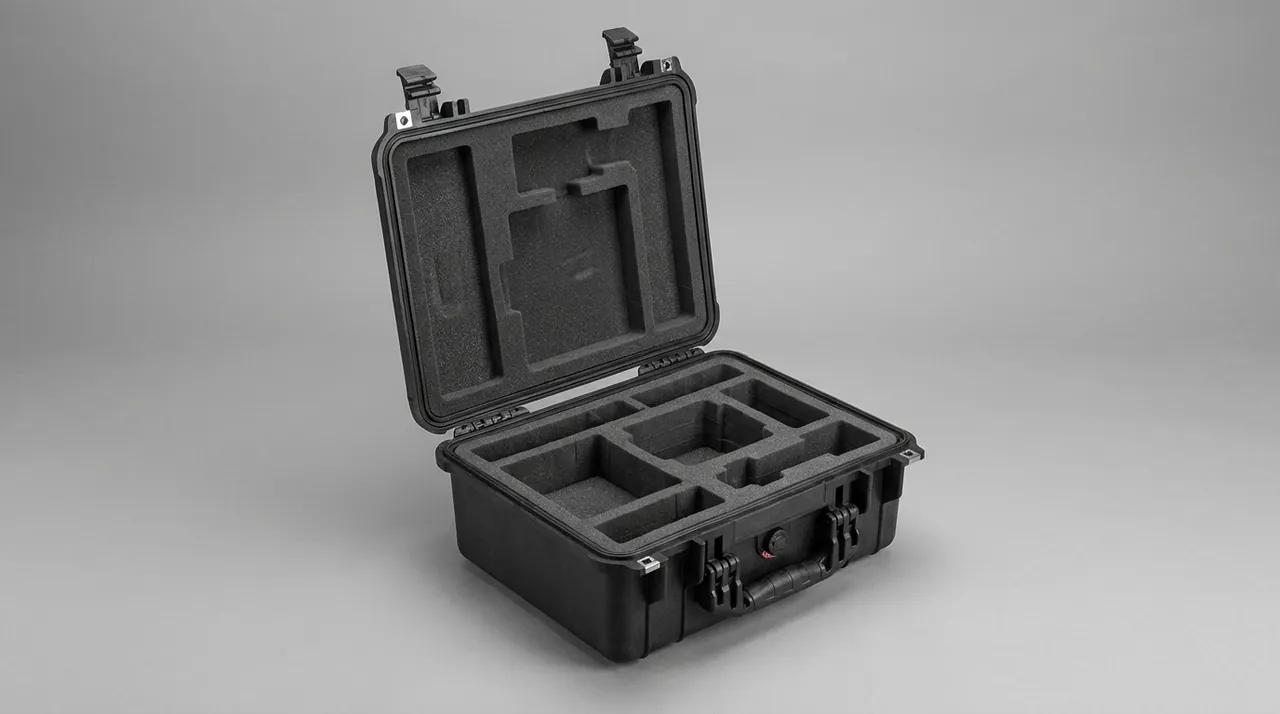
Achieving no contact is not a matter of adding more foam; it means holding the taper in free space. JUNZHIJIA normally machines a compartment keyed to the seat bore positions, seats the valve seat in a contoured EVA or polyurethane cradle, and takes contact only on two non-mating bands of the outer diameter plus the lower end face, leaving cavities above and below the taper. The threaded puller hole next to the outer diameter is plugged with a plastic insert so sand and dust cannot enter. When a customer requires the fluid end to ship in assembled condition, an injection-moulded guard covers the seat bore opening, its inner wall lined with non-woven cloth and the guard vented so that temperature swings do not create a vacuum that draws in dust. The figure below shows the contoured compartment and non-contact location arrangement.
Two easily overlooked details belong to the same rule. The first is cleaning residue: valve seats are often magnetic particle or dye penetrant inspected before dispatch, and incomplete cleaning leaves penetrant or developer adsorbed on the taper, which both prevents rust oil from bonding and may carbonise under hot well conditions. Clean with fresh solvent and dry thoroughly after inspection, then pack separately. The second is rust preventive choice and placement: tapers and seal faces can take a thin hard-film rust oil, but compatibility with the later assembly operation must be confirmed and the film must stay thin so that taper seating is not affected. Threads and mating bores should avoid runny grease and instead rely on rust paper or VCI vapour-phase material, whose molecules volatilise inside a closed cavity and protect both alloy and stainless steels, making it the safer choice for long ocean voyages. When one case carries several components that all have sealing faces, plan the compartments and face isolation together, following the approach used for pressure vessel component cases.
Plungers: Preventing Scratches on Ceramic and Hard Chrome Coatings
The plunger is the most frequently replaced part in a frac fluid end and also the one that is easiest to ruin and least acceptable to lose. Two surface treatments dominate. Hard chrome plating is typically tens of micrometres thick, hard but with a sensitive bond interface. Thermal sprayed ceramic, using alumina, titania or a composite, can build a coating a few tenths of a millimetre thick with better wear and corrosion resistance, but ceramic is brittle and reacts badly to point impact and shear. Both share one decisive property: once the coating chips, flakes or is scored through, it cannot be repaired on site and the plunger is scrapped.
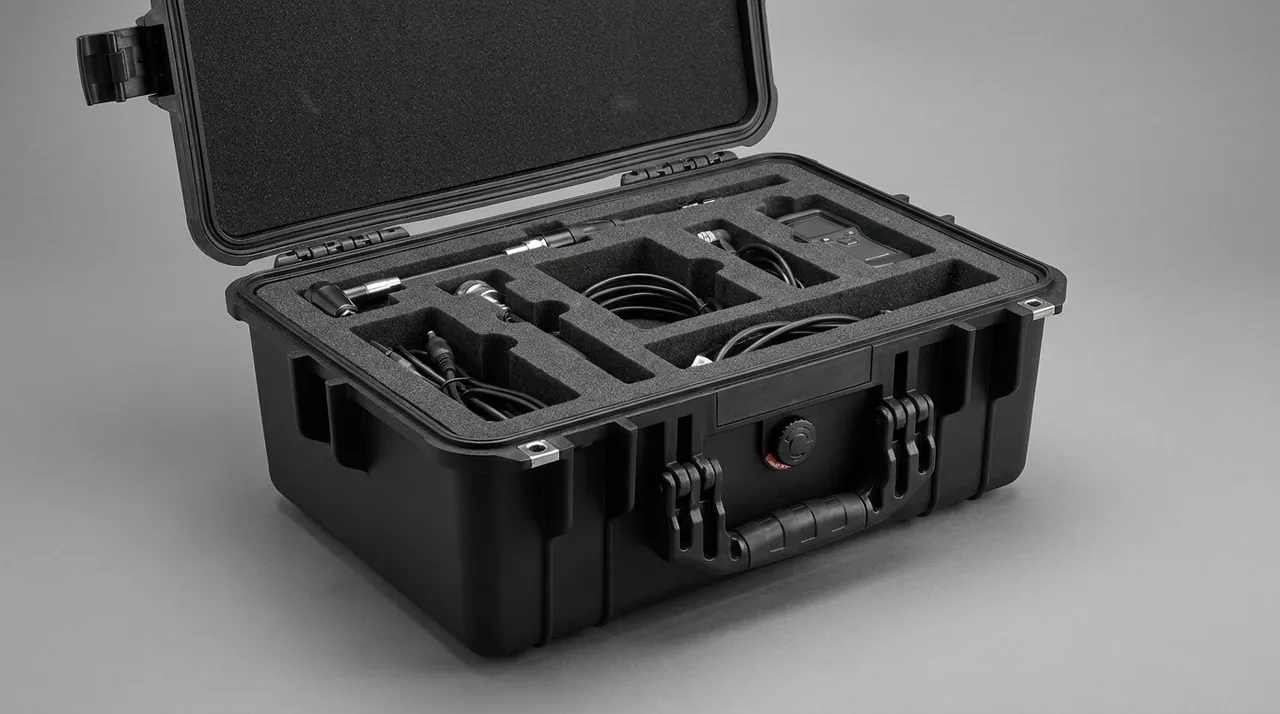
The protection target is therefore not resistance to large shock but elimination of every point contact. JUNZHIJIA applies three rules. First, each plunger occupies its own cavity and never shares a cavity with a valve body, valve seat, flange or any other metal part; when several plungers travel in one case, each is separated from the next by at least 20 mm of soft liner and axial travel is limited to 5 mm. Second, the outside diameter is wrapped over its full circumference using a non-woven inner layer with a closed-cell EVA outer sleeve, and tape, labels or tie wraps must never be stuck directly to the coating, because the shear of removal alone is enough to lift ceramic. Third, both ends are capped: the coated end takes a tapered plastic or EVA cap, and the power end, with its thread or flange, takes a thread sleeve or guard ring so that threads are not bruised and coating edges are not loaded. The figure below shows the full wrap and end capping arrangement.
Storage orientation also matters. A plunger with a large length-to-diameter ratio, often 8 to 15 times, will sag slightly if it is left unsupported horizontally, and straightness can drift over long storage. Support it at multiple points of equal height, at both ends and the middle with even spacing, using soft blocks whose width is at least half the plunger diameter to keep contact stress low. The plunger should lie horizontally, never lean upright against a wall and never rest diagonally against a case wall where it would touch on a point. If vertical storage is unavoidable to save space, use a full-height vertical rack with an axial stop at the top and a spherical or soft cradle at the bottom.
Cleanliness of packaging material also affects the coating. EVA and polyurethane foams can retain blowing agents and low-molecular volatiles from production, which may migrate onto a coating during long contact and leave an organic film that is hard to remove. Liner material that touches the coating should therefore be a low-outgassing grade, or a non-woven or PE film barrier should be placed at the interface. The cleanliness controls that JUNZHIJIA applies in the EVA foam insert custom process transfer directly: every foam piece that touches a precision face is aged, cleaned and checked for volatiles. When ceramic and hard chrome plungers ship together, they should be separated by case or at least by compartment and clearly marked, so that the wellsite cannot misread them by appearance and install the wrong type in the wrong pressure position.
Packing and Seal Components: Ageing Control for Rubber and Polyurethane
Packing rings, also called stuffing box packing, and the associated seals are the soft tissue of a frac fluid end. Their unit value is low, yet they determine leakage rate and the service life of the parts around them. Typical items include plunger packing rings, support rings, back-up rings, O-rings and oil seals, in materials ranging from aramid or PTFE braid to nitrile, hydrogenated nitrile, fluoroelastomer and polyurethane. In transit and storage these materials fear four things: heat, ultraviolet light, ozone and oil. Heat accelerates crosslinking ageing and plasticiser migration, which shows up as higher hardness and lower resilience. Ultraviolet and ozone crack the surface. Oil and organic solvents can swell the compound or extract its curing agents.
The protection logic is completely different from that for metal parts, because elastomers fear the environment while metal fears contact. The correct method lifts the seals out of the main case and makes them a dedicated seal sub-case placed in an independent compartment. The sub-case should be light-tight, either from an opaque lid or a blackout bag; held at low humidity with desiccant sized to the cavity, silica gel commonly at 50 to 80 g per cubic metre; kept clean, with dust-free and grease-free liner surfaces; and divided into cells so that different sizes cannot mix. Label the case with compound grade, size, production date and recommended use-by date. Storage temperature is best kept at or below 25 degrees C without repeated swings, away from motors and transformers that generate ozone, a principle that applies equally to the thermal and moisture design of extreme temperature protective cases.
Polyurethane parts carry two extra risks. The first is hydrolysis: in hot humid conditions polyurethane degrades by hydrolysis and becomes tacky with reduced strength, so the cavity must stay dry and polyurethane must not share a compartment with any water-bearing component. The second is interaction with oil-based media. Compatibility of polyurethane with oil-based mud and diesel is already confirmed case by case for downhole service, and if the parts ship alongside lubricating grease the compound can swell early and change assembly dimensions. Rubber parts add a third concern, namely that they must not be stored under compression. Components with metal inserts, such as certain support rings, take a permanent set if left loaded, so they should travel in a free state without interference contact against hard location blocks. All of this shows that a seal sub-case is not an accessory compartment but an element that deserves its own liner design and humidity control scheme, at the same engineering level as the block itself.
Valve Bodies and Seats: Matched Isolation of Erosion-Prone Parts
A valve assembly consists of the valve body, the valve insert that forms the sealing element, the valve seat, the guide and the spring, and it is the part of the fluid end that suffers the most severe erosion. As proppant-laden fluid accelerates through the valve gap at high velocity, the sealing taper and the flow passages of body and seat develop the characteristic washout pattern of service, with ring grooves on the taper, thinned passage walls and worn guides. Because service is already this harsh, transport must not add impact damage on top. A dent put into a taper during shipping can cut the life of a brand-new assembly to a fraction of its normal figure.
Transport protection for valve assemblies has to resolve three competing requirements. The first is match and separation. Body and seat are lapped as a pair, so they should travel in the same case and carry a matching pair number, yet inside the case their tapers must never touch. The solution is a contoured compartment with a central locating post, so body and seat each seat in their own position with tapers facing away from each other, a soft divider between them and the pair number printed on the label. The second is spring set. A valve spring is comparatively long in its free state, and if it is compressed in the case, for example by a heavier part lying on top, its free length will shift over time and change the opening and closing behaviour. Springs belong in their own cell, held at free length or at the compression specified by the manufacturer, and must never be casually stacked. The third is the relationship between insert and taper. A valve insert is an ageing-prone elastomer, and long contact under load against a metal taper causes both deformation and migration of curing agents, so the insert should be wrapped separately and then placed in the same cell.
Erosion-prone wear parts hide one more risk, namely internal residue. A body or seat that returns to the factory for refurbishment and is then shipped again can still hold sand and metal swarf in its passages, and transport vibration drives those particles repeatedly against the taper as a second damage cycle. A new part that is cleaned but not sealed at the ports can take in salt-spray moisture during an ocean crossing and arrive with rust that later becomes a particle trap after assembly. Valve parts therefore follow a four-step sequence before boxing: wash, dry, plug and protect. Plug passages with soft caps or PE inserts, coat tapers with rust preventive and wrap in vapour-phase paper, then place the unit in a vacuum or barrier bag as weight and geometry allow, and finally into the compartmentalised liner. When a customer buys both valve assemblies and blocks, ship them by pressure rating with clear marking so that components of different ratings cannot be interchanged, the same no-mixing rule that governs refinery valve cases.
Wet Sour Service: Protection in the NACE MR0175 and ISO 15156 Context
Fracturing in shale gas and in sour oil and gas wells frequently involves well fluids that contain hydrogen sulphide together with carbon dioxide, creating a wet sour corrosion environment. The effect on metals goes far beyond general corrosion, and the more dangerous mechanisms are sulphide stress cracking, hydrogen induced cracking and stress oriented hydrogen induced cracking. Hydrogen atoms generated in wet hydrogen sulphide service diffuse into the steel, accumulate at stress concentrations and cause brittle cracking that often happens without warning. The industry generally uses NACE MR0175, technically aligned with ISO 15156, as the basis for material selection and hardness control in sour service, applying an upper hardness limit to carbon and low-alloy steels together with restrictions on cold deformation and welding.
It must be stated clearly that this standard addresses the in-service resistance of the material inside the well environment and is not the same subject as transport protection. The two nevertheless intersect at one point in transit, and that point is moisture. A wet hydrogen sulphide environment requires liquid water and hydrogen sulphide to coexist, so if a component stays dry throughout transport and storage, the external conditions for hydrogen permeation do not exist. The practical value of transport protection for sour service parts therefore lies in three actions. First, cleaning and drying must be thorough: a part that has been pressure tested or run in service may retain sour well fluid, test water or condensate, and if that liquid is sealed inside the packaging it keeps the interior wet for months while sulphides can concentrate in the closed volume, creating an additional risk to hard surfaces and stress concentration zones. Wash with clean fresh or deionised water, blow dry with compressed air, then apply desiccant and vapour-phase protection together. Second, chemicals must not share the shipment: pickling agents, sulphur-bearing compounds, chloride solvents and alkaline cleaners must never travel in the same case or container as sour service parts, because their vapours can build a corrosive atmosphere inside the cavity. Third, sealing and moisture protection must match the journey: projects bound for the Middle East, North America or offshore platforms should use a case rated IP65 or better with a pressure equalisation device to handle the breathing caused by temperature swings at sea.
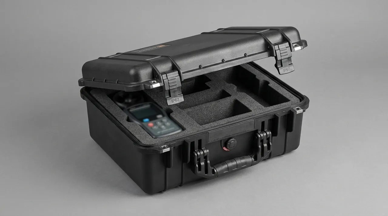
Labelling and traceability matter in sour service as much as the packaging. Parts should carry material grade, hardness control requirement and the applicable standard number so that the wellsite can verify that the components match the intended service environment, and material certificates plus heat treatment records should travel with cases containing material assessed to NACE MR0175 or ISO 15156. This requirement resembles contamination control in hydraulics: the principle that clean and dry comes before sealing, which is emphasised in hydraulic lift component cases, holds equally here. When a customer wants a higher grade of protection, size it by the IP protective case method, using route, number of transfers and storage duration rather than simply taking the highest available rating. The figure below shows moisture-proof packing and desiccant layout for sour service components.
Discharge Manifolds, Flanges and Thread Protection for Fasteners
The fluid end has a large number of connection parts in many sizes, and these are the easiest to treat carelessly and the slowest to fit on site. Discharge manifolds, discharge flanges, suction manifolds, plugs and sealing nipples are pressure-retaining components whose metal ring grooves, often in a lens or ring joint configuration, and flange faces control the sealing reliability of the whole pump. Stay rods, nuts and fluid end bolts carry very high preload, so any bruise on a thread leads to abnormal torque or insufficient preload during assembly and can, in the worst case, cause loosening and a washout in service.
Thread protection relies on a sleeve, not on wrapping. PTFE tape or cloth wound round a thread cannot carry the compressive load of transport and leaves fibres in the thread root, so use a plastic or rubber thread sleeve matched to the thread size, with an elastic inner layer giving area contact and even load distribution. Large stay rod threads suit a two-piece sleeve with a clamp band so the protection cannot fall off. Mark the sleeve with its size to prevent mixed use during unpacking. Pressure-retaining flange faces and ring grooves take a rigid cover plate, in hard plastic or aluminium, with a soft pad between plate and sealing face and the plate edges secured by strapping so that vibration cannot move it.
Fastener management also involves maintaining sets. Stay rods and nuts for a frac fluid end are normally supplied together to a defined preload requirement, and mixing batches can produce uneven preload. Fix them in the case as grouped plates, one cell per plate, each labelled with model and quantity, and include the torque requirement and tightening sequence with the shipment. For long slender items such as stay rods, protection goes beyond the thread to preventing bending: support spacing must not be excessive, and a multi-point V-shaped cradle along the case length with soft inner lining avoids metal to metal contact. Every metal connection part should be derusted, cleaned and dried before protection, then wrapped individually in vapour-phase paper. Where a customer specifies a cleanliness requirement, for example for sour service or a high-purity pressure testing system, set a cleanliness class and sample it at acceptance along the lines of protective case cleaning and residue control.
Liner Materials and Compartment Design: EVA, XLPE, HDPE and Steel Skeleton
The liner of a frac pump case has to balance cushioning, load bearing, wear resistance, cleanliness and cost, and no single material satisfies all of them, so practical schemes are almost always composite. The table below compares the common materials and indicates where each is used, as a starting point for selection.
| Liner material | Cushioning | Load capacity | Wear resistance | Cleanliness | Typical location |
|---|---|---|---|---|---|
| --- | --- | --- | --- | --- | --- |
| EVA foam, including anti-static grades | Medium | Low | Medium | High | Plunger wrap, valve seat contour cells |
| XLPE crosslinked foam | Good | Medium | Medium | Medium | Buffer layer for medium parts, cavity floor |
| HDPE board | Low | High | Excellent | High | Dividers, tray faces, taper guards |
| Cast polyurethane | Excellent | Medium | Good | Medium | Contoured wraps and sleeve linings |
| EPP moulded | Excellent | Medium | Medium | Medium | Reusable case core |
| Aluminium profile or steel skeleton | Very low | Very high | High | High | Block load trays, case reinforcement frames |
The standard composite is a three-layer arrangement. The outer layer is the case body itself, in aluminium alloy, engineering plastic or a steel frame, providing sealing and external impact resistance. The middle layer is the load skeleton in steel or aluminium profile, routing heavy part weight into the outer frame. The inner layer carries the functional liner, meaning contoured EVA, HDPE dividers and polyurethane sleeves, and handles location, isolation and precision face protection. Each material then does only what it is good at, and worn liner elements can be replaced singly instead of scrapping the whole case.
Compartment design is the skeleton of the whole liner scheme, and for frac pump parts it reduces to four statements: heavy and light parts in different cavities, precision faces and non-precision faces loaded differently, metal and elastomer parts in different cavities, and different sizes and pressure ratings in different cells. In practice this means arranging parts in the 3D model first, keeping the heaviest parts centred and low so that the centre of gravity projection falls near the geometric centre of the case, laying slender items such as plungers along the case length rather than across the middle where support is weak, and treating the seal sub-case as an independent unit embedded in its own main-case cavity with a buffer layer between so that main-case deflection cannot press on it. Any unsupported span longer than 300 mm should gain an extra support point.
Details of liner material also affect reliability. Every foam piece that touches a coated surface should be a low-outgassing, low-dust grade that has been aged; cut faces of EVA and HDPE should be sealed so particles cannot shed; and contour liner tolerances should give a gap of 0.5 to 2 mm against the part profile, since a smaller gap makes assembly difficult and can scratch while a larger one destroys the locating function. For cases that open and close repeatedly, make liner elements removable and fixed with clips or dowels so that cleaning and replacement are practical. JUNZHIJIA has compiled water vapour transmission and compression set data for these materials in the case foam material comparison, which can serve as a reference during scheme review.
Heavy Lifting, Eccentric Part Fixation and Centre of Gravity Marking
Loading and unloading of frac fluid end parts happens at wellsites and ports, where conditions are poor, lifting gear varies and operators change frequently. The case must therefore explain itself, using clear markings and defined lift points to make the correct method the obvious one. JUNZHIJIA applies the following rules to heavy-part cases, and they can be used directly as technical purchasing conditions.
The first is marking centre of gravity and lift points. Both sides and both ends carry the centre of gravity symbol and rated lift weight, with lift points marked by contrasting colour rings: four rings of the same colour for a four-point lift, or a single ring with a central arrow for a single-point lift, never a mixture. Lift point structures should withstand at least twice the total case mass, with reinforcement where the lug meets the frame by weld or bolt. The second is rules for turning and tilting. A block normally does not need to be turned, and if a change of orientation is required it should happen outside the case; there must be no levering or jacking inside. Mark no-levering on the case walls. The third concerns stacking. Rate the stacking load against unit mass, fit metal stacking corners at the four top corners, and mark maximum stack height and no-standing on the lid. The fourth is tie-down. On a container or flatbed, secure from the case frame rather than from the lift points, add corner guards where straps touch the case, and hold strap angles in the 30 to 60 degree range so that lateral force does not rise unnecessarily.
Eccentric parts need a dedicated fixture. Valve seats, blocks and some manifolds have a centre of gravity offset from the geometric centre, and when they are held only by foam on four sides they gradually walk under sustained vibration until they contact a case wall along a line. Three measures fix this. First, add a low-hardness location block on the heavy side so that stiffness either side of the centre of gravity is asymmetric and rocking is suppressed. Second, fit an adjustable pressing element such as an elastic strip or screw block on the opposite side to push the eccentric part back onto its location face. Third, machine a step into the liner that matches the eccentric profile so that the step shoulder carries the inertia load instead of relying on friction. Preload on pressing elements is graded by part mass, tight enough to prevent movement yet not so tight that it crushes the liner or marks the part.
The lifting operation itself needs procedural discipline. Supply a handling card with the case that states sling type, lift point positions, the maximum permitted tilt angle and the prohibitions, such as angled pulls, single-point lifts of unbalanced parts and slings touching oil or sharp edges. Require a visual check before any port lift for case dents, loose latches and deformed lift points, with the case taken out of service if any is found. This practice outperforms any written promise in real overseas projects. Where a part must be lifted again after the case is opened on site, include a lifting point diagram inside so that nobody puts a wire rope directly onto a plunger coating or a valve seat taper.
Sealing Grade, Venting and Internal Pressure Equalisation
The sealing grade determines how well the case isolates its contents from salt spray, sand dust and rain, and for high-value frac pump components that seal is the first barrier against corrosion and contamination. Match the grade to the route and storage conditions. Domestic road transport with short turnaround is usually served by IP54 to IP55 as defined in GB/T 4208, equivalent to IEC 60529. Ocean freight, open port storage and multimodal transfer call for IP65 or better. Offshore platform storage or a case directly exposed on deck suggests IP66 to IP67. Note that the IP rating describes the as-shipped condition and depends on even compression of latches and gasket, so a loose latch or a gasket pinched by a sand grain drops the effective rating straight away.
A good seal must also breathe. A well-sealed case crossing climate zones goes through sharp temperature changes, and as the internal air cools it creates a vacuum that draws moist, salt-laden air in through the weaker points of the seal. When the temperature rises again, positive pressure pushes that moisture towards the coldest wall where it condenses. Medium and large sealed cases should therefore carry a pressure equalisation valve or breathable membrane assembly that slowly balances internal and external pressure while blocking liquid water and particles. JUNZHIJIA summarises the matching of air flow to protection grade in case pressure equalisation valve selection, where the required flow is calculated from case volume, journey duration and temperature range. For cases carrying high-value precision components, add a humidity indicator card so that protection failure can be spotted in seconds on arrival.
Latches and gasket reliability need design attention as well. Frac pump cases are usually large with long lids, and single-point latches tend to open locally under vibration. Use a multi-point compression pattern with latch spacing no greater than 400 mm, choose anti-loosening catches, and select a gasket compound with low compression set, such as nitrile or silicone, in a hollow tube or double-lip profile. This logic matches the discussion of clamping force distribution in toolbox hinge latch seal: sealing is decided by the weakest point, not the strongest. Cases that open frequently should carry a spare gasket with a stated replacement interval and inspection method. For sour service or humid regions the gasket should also resist oil and low temperature so that winter hardening cannot defeat the closure.
Test Basis, Standard References and Arrival Acceptance
Whether a case survives real distribution is a question for standard tests rather than verbal assurance. The table below lists the verification options for frac pump component cases. MIL-STD-810H is cited only as a source of environmental test methods, and JUNZHIJIA makes no claim of any military certification.
| Standard | Stage covered | Main verification | Acceptance point |
|---|---|---|---|
| --- | --- | --- | --- |
| ISTA 3E or 3H | Unitised transport simulation | Random vibration, drop, shock | No part displacement, no precision face damage |
| GB/T 4857 series | Domestic road packaging | Stacking, drop, sine vibration | No permanent case set, liner effective |
| ASTM D4169 | Distribution cycle risk | Drop and vibration by level | Level chosen from the real logistics route |
| GB/T 4208 and IEC 60529 | Case sealing | Dust and water tests | Judged against the target IP grade |
| GB/T 10125 | Corrosion verification | Neutral salt spray | Sampled parts free of base metal red rust |
| MIL-STD-810H | Environmental method reference | Random vibration, temperature and humidity cycling | Not a military certification, method reference only |
Test design should match component value. For heavy items such as blocks, drop height is limited by unit mass and is necessarily low, so the emphasis belongs on whether internal location survives rather than on case appearance. For plungers and valve seats the emphasis is on coating and taper integrity after vibration. For the seal sub-case the emphasis is on humidity retention after temperature and humidity cycling. Test sequences can follow transport testing procedures and MIL-STD-810H environmental compliance, but severity levels should be set for the actual product rather than copied.
Acceptance on arrival works best in three layers. The outer layer checks latches, lift points and gaskets for deformation or cracking and the case for severe dents and corrosion. The liner layer checks location blocks for looseness, desiccant for saturation and colour change, vapour-phase packaging for integrity and the humidity indicator for colour shift. The part layer inspects each precision face in turn: the plunger outside diameter for bright spots, scores and chips, using a magnifier and white light and, where needed, measurement of diameter and roughness; the valve seat taper for impact marks and rust spots; the block end face and seat bores for bruising; flange ring grooves and threads for damage; and elastomers for hardening, tackiness and deformation. Key parts merit full inspection while general parts can follow a sampling plan sized in line with the case acceptance AQL approach. Record any damage photographically at once and classify it as packaging responsibility, transport responsibility or manufacturing defect, so that the claim stage does not turn into an argument.
Marking, Traceability and Model-Matched OEM/ODM Supply
Case marking is the command language of transport safety and the entry point of the traceability system. At least two end faces and two side faces should carry the component name and model, unit and total mass, centre of gravity and lift point symbols, this-way-up, keep-dry and keep-dark markings, and maximum stack height, with pictograms and wording following GB/T 191 and GB/T 13384 and English equivalents plus destination port information added for export cases. For traceability, give each case a unique serial number and QR code that resolves to the packed component list, material certificate numbers, heat treatment records, rust preventive treatment date and validity, and the frac pump model and pressure rating served. A fluid end shipped as a set, meaning block plus three plungers plus valve assemblies plus seals, should be marked box X of Y with a master set number to prevent short shipments.
Frac pump models are numerous and fluid end dimensions can differ even within one model across years, so standard cases rarely fit well and model-specific customisation is the more efficient route. The JUNZHIJIA OEM/ODM flow has five steps: the customer provides drawings or physical parts, together with service conditions and sour service information where relevant; 3D scanning builds a model in which every precision face and no-touch zone is marked; liner compartment and case load-bearing schemes are reviewed with defined cushion thickness, location points and guard types; a prototype case is built and trialled, with drop and vibration verification where required; and batch production follows together with matched seals and fasteners. Model-matched sealing is the core value-add, since plunger diameter, seat bore taper specification, flange size and rod length differ between pump models, so JUNZHIJIA pre-sets the correct seals and fasteners by model list and supplies assembly torque and sequence information with the shipment, cutting on-site procurement and mismatch risk.
For long-term frac service suppliers, build a combined model, case type and seal database and record every repeat order and field feedback: which components repeatedly show a particular damage mode, which liner revision produced the lower arrival defect rate, and which seals behave unexpectedly in a particular duty. Once enough data accumulates, case design moves from experience-driven to data-driven, which is the practice JUNZHIJIA applies across several oil and gas equipment verticals. During selection, the capability checklist in how to choose a protective case OEM factory can be used to confirm design capability, liner machining accuracy, test facilities and quality documentation, avoiding a quality slump at peak delivery.
Frequently Asked Questions FAQ
Q: Why can a frac pump fluid end block not be shipped in a common wooden crate with foam? A: A block commonly weighs 1.5 to 4 tonnes with an offset centre of gravity, and a common wooden crate floor and side panels cannot spread such a concentrated load. The bending moment of a lift or a turn passes through the bottom foam into the block mating faces, causing ovality and end face distortion that cannot be seen by eye yet appears as a slow weep after installation. Foam damps vibration rather than carrying weight, so using it as the load path crushes it quickly and destroys location, after which the block slides. The correct structure shares duties: a steel or aluminium profile skeleton routes weight into the case outer frame, foam handles cushioning and surface protection only, and precision faces are held clear in contoured cells. JUNZHIJIA distributes load through four corner legs, rates stacking at a 1.5 safety factor, and requires no visible permanent set after a loaded lift. When a customer ships a fluid end in assembled condition, add mid-span supports and a top restraint so that stay rods do not take extra bending.
Q: Why is a shallow score on a plunger coating enough to reject the plunger? A: Because the failure mechanism of a frac plunger starts at the surface defect. Hard chrome and ceramic coatings are both hard and low in toughness, so a score only a few tens of micrometres deep still breaks coating continuity, creates a stress concentration and exposes the base metal. In high-pressure sand-laden service the exposed base metal erodes first, the coating then lifts and flakes from the score edge, and the flaked area grows into an axial groove. Plunger and packing fit degrades quickly, leakage rises and the packing is damaged with it, a progression that usually needs only a short running period. The industry therefore treats visible scores, pits and chips on the coating as unacceptable. What transport must eliminate is not large shock but every point contact: a dedicated cavity, full wrap in soft material, end caps, and no tie wraps stuck to the coating. JUNZHIJIA also recommends sweeping the plunger axially with white light and a magnifier at acceptance and sampling diameter and roughness, so the problem is stopped before installation.
Q: Valve bodies and seats are lapped as pairs, so can they be packed separately? A: They can be packed separately as long as the pair identification is preserved and they travel in the same case, and there is no contradiction between the two. Although the sealing faces are lapped as a pair before assembly, taper accuracy depends on the geometric precision of each part, so separate packing does not change the pairing. What does change pairing is mixing and misallocation. The recommended approach is a contoured compartment with a central locating post, body and seat each in their own position with tapers facing opposite directions, a soft divider between them and the pair number printed beside the cells. Parts are then issued by number after opening, and cannot be mixed with another batch. When a customer requires assembly condition shipping, with body and seat already mated, place a thin non-woven or rust paper layer between the tapers and restrain axial movement with external blocks so that vibration does not produce micro-motion wear on the taper. In both cases, wash, dry and plug the passages before boxing, since residual sand and swarf striking the taper under vibration do more damage than a single impact.
Q: What special packaging requirements apply to frac pump parts for sour service? A: The core risk in sour service is sulphide stress cracking and hydrogen induced cracking caused by wet hydrogen sulphide. Material selection and hardness control are governed by standards such as NACE MR0175 and ISO 15156, and that belongs to manufacturing. The transport requirements concentrate on cutting off the moisture condition and avoiding a corrosive atmosphere. First, any part that has been pressure tested or run in service must be fully cleaned and dried, because sour well fluid, test water or condensate sealed inside packaging keeps the cavity wet for months and can concentrate sulphides, adding risk to hard surfaces and stress concentration zones. Second, never ship pickling agents, sulphur compounds, chloride solvents or alkaline cleaners in the same case or container, as vapours can create a new corrosive atmosphere. Third, match sealing grade to journey length, using IP65 or better plus pressure equalisation for ocean and offshore projects. Fourth, supply material certificates, heat treatment records and the hardness control requirement so that the wellsite can confirm the components suit the intended service.
Q: Why do small items such as packing rings and O-rings need their own case? A: Because their failure mechanisms differ completely from those of metal parts, and packing them together guarantees mutual harm. Metal parts fear impact while elastomers fear heat, ultraviolet light, ozone and oil. If packing rings share a cavity with a block, the elastomer is repeatedly squeezed by the mass of the heavy part and takes a permanent set, while its surface picks up metal particles and rust oil that are hard to remove. More importantly, the environmental needs are opposite: metal parts want rust oil and vapour-phase paper, elastomers want no oil, no light and controlled humidity, and one cavity cannot satisfy both. JUNZHIJIA therefore builds the seals into a dedicated sub-case embedded in a main-case compartment, kept dark, held at low humidity with desiccant at 50 to 80 g per cubic metre, divided by size, labelled with compound grade and production date, and stored in a free state so that compression cannot cause permanent set. Polyurethane additionally needs protection from hydrolysis at high temperature and humidity, and rubber must stay away from ozone-generating electrical equipment, details rarely covered by general packaging practice.
Q: If the case is sealed to IP65, why is a venting feature still needed? A: Because a fully sealed case breathes during transport between climate zones, and that breathing is often the real reason moisture protection fails. On an ocean voyage a case may move from a deck at over 30 degrees C into a hold or a high-latitude port at under 5 degrees C. The internal air cools and contracts, creating a vacuum that pulls moist, salt-laden air in through the weaker parts of the seal. When the temperature rises again the internal positive pressure drives that moisture towards colder walls, where it condenses into droplets and eventually leaves rust spots and mould on component surfaces. A pressure equalisation valve or breathable membrane does not weaken the seal; it lets air exchange very slowly to balance differential pressure while blocking liquid water and particles. Selection requires calculating the necessary air flow from case volume, journey duration, temperature range and target protection grade, and the protection rating of the vent element itself must be no lower than that of the case. JUNZHIJIA recommends adding a humidity indicator card so that failure is visible on arrival.
Q: What are the specific risks of shipping mixed frac pump spares? A: Mixed shipping carries three specific risks. The first is wrong installation: blocks of different pressure ratings, plungers of different diameters and valve seats of different taper specifications look similar, and a wellsite cannot reliably tell them apart by eye. A wrong installation produces a mating face that will not seat or a preload that is too low, so the joint leaks at pressure test and in the worst case washes out in service. The second is mutual damage: when heavy and precision parts share a cavity, the inertia of the heavy part under vibration is enough to chip a plunger coating and dent a valve seat taper, and neither can be repaired. The third is contamination and mixing of parts: elastomers in the same cavity as oiled metal absorb grease and metal dust, loose fasteners are lost or mixed with another batch, and preload becomes uneven. Separate by pressure rating, by pump model and by component class: blocks apart from plungers, valve assemblies in matched cells, seals in their own sub-case, and fasteners fixed as labelled plates carrying model and quantity. Mark cases as set members and box X of Y so that nothing arrives short or mismatched.
Q: How should tooling lead time and acceptance points for a custom liner be planned? A: Tooling lead time depends on part complexity, whether 3D data is available and how much verification is required, so procurement should plan design review, trial fitting and verification into the schedule rather than asking only for a shipping date. After drawings or physical parts arrive, 3D modelling and precision face marking come first, then compartment layout and material selection, then a prototype case with trial fitting and, where needed, drop and vibration verification. Acceptance points include whether the liner gap against the part falls inside the design range; whether location blocks touch only non-precision surfaces; whether precision faces keep sufficient clearance; whether the load structure is rated with a 1.5 safety factor; whether latches reach the target IP grade; and whether material certificates, liner drawings and test reports are complete. JUNZHIJIA supplies 3D liner drawings at scheme stage so that the customer can confirm before tooling, avoiding rework after the mould is cut.
Conclusion
Protecting a frac pump fluid end and its plungers means assigning four jobs to the right structures: steel skeletons carry the load, contoured soft liners locate parts, guards and vapour-phase materials shield precision faces, and seals with desiccant manage the environment. JUNZHIJIA builds model-matched liners and reusable sealed cases so expensive components arrive intact.
Related reading