

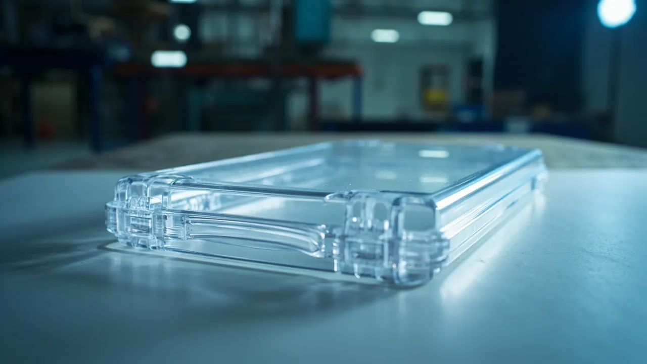
Short answer: a protective case can be made transparent, but transparency and high impact resistance are a trade-off to be balanced in processing, not something solved by switching the material to PC. The real difficulty with a clear lid lies not in the material but in three process constraints: wall thickness, because transmittance falls and haze rises as the wall thickens; optical defects, because flow marks, weld lines and internal stress are directly visible on a clear part while being completely invisible on a dark one; and structure, because ribs, bosses and internal steps "develop" like a photographic image inside a transparent part, ruining appearance. The feasibility of a transparent protective case therefore depends on whether you can accept four costs: structural simplification, uniform wall thickness, higher mould surface grade, and lower yield. This article gives definitions and quantitative relationships for transmittance and haze, the causes and countermeasures for six process constraints, a comparison of five transparent materials, the essentials of matching a clear lid to the sealing structure, test standards and verification methods, and a checklist for judging whether a project can be made transparent at all.
One concept must be clarified first: "transparent" is not a binary property but a continuous quantity defined by two metrics together — transmittance and haze. A panel transmitting 90% of light with 30% haze looks like frosted glass; a panel transmitting 88% with 2% haze looks clear. Enquiries often simply say "must be transparent" without giving target values for these two metrics, and that is the single largest source of the gap between sample and expectation. For background on materials, see protective case plastic materials compared.
Table of Contents
- Short Answer: Transparency and Impact Resistance Are a Trade-Off
- Quantifying Transparency: Transmittance, Haze and Optical Distortion
- Why PC: The Best Combination of Clarity and Impact Resistance
- Process Limit One: Wall Thickness versus Transmittance and Haze
- Process Limit Two: Flow Marks, Weld Lines and Gate Marks
- Process Limit Three: Internal Stress, Birefringence and Optical Distortion
- Process Limit Four: Mould Surface Grade and Polish on Release
- Process Limit Five: UV Ageing and Yellowing
- Process Limit Six: Structural Limits — Ribs "Develop"
- Clear Lid and Case Sealing: Shrinkage and Flatness Challenges
- Transparent Materials Compared: PC, PMMA, PS, PETG and PP
- Test Standards and Verification Methods
- Application Scenarios and Selection Advice
- Clear Lid Customization in OEM/ODM Projects
- Frequently Asked Questions
- Conclusion and Further Reading
Short Answer: Transparency and Impact Resistance Are a Trade-Off
State the trade-off first; only then do the process constraints have a foundation.
The physical origin of the trade-off. Whether a material is transparent depends on whether it forms an optically uniform microstructure: amorphous, non-crystalline, non-oriented and non-phase-separated materials are the easiest to make clear. Impact resistance, by contrast, often relies on energy dissipation mechanisms such as molecular chain orientation, dispersed rubber phases, and shear yielding bands. Some of these mechanisms — orientation and phase separation in particular — destroy optical uniformity. That is the fundamental reason "clear plus impact-resistant" is hard to achieve together.
Polycarbonate (PC) is the classic resolution of this trade-off. PC is an amorphous polymer, optically clear, while its molecular structure (the rigidity of the bisphenol A backbone plus the toughness of the carbonate linkage) confers very high impact strength. PC is therefore the first-choice material for transparent protective case lids. But PC has its own problems: relatively poor flow, sensitivity to shear, a tendency to retain internal stress, only moderate UV resistance, and notch sensitivity. These problems are amplified in thick-walled clear parts.
A realistic judgement. For a clear lid with a long edge over 500 mm and a wall over 5 mm, process difficulty and cost rise sharply; for a small clear viewing window or a small-to-medium clear case, feasibility is much better. The first question is therefore not "can it be transparent" but "how large, how thick, and at what optical grade."
| Requirement combination | Process difficulty | Typical approach | Main cost |
|---|---|---|---|
| --- | --- | --- | --- |
| Small clear viewing window (under 200 mm) | Low | PC injection moulded, uniform thin wall | Controllable cost |
| Small-to-medium clear lid (200-500 mm) | Medium | PC moulded with high-polish tool | Lower yield |
| Large clear lid (over 500 mm) | High | PC moulding or thick-sheet thermoforming | High cost, high defect risk |
| High clarity plus high impact plus high flatness | Very high | PC with a tight process window | High yield and cost pressure |
| Translucent or frosted (low optical demand) | Low | Ordinary PC or PP | Defects masked |
Quantifying Transparency: Transmittance, Haze and Optical Distortion
Transparency that cannot be quantified cannot be accepted. Three metrics must be defined.
Metric one: luminous transmittance. The ratio of transmitted visible light flux to incident flux, expressed as a percentage. Test methods may reference ISO 13468 (determination of total luminous transmittance of transparent plastics) or ASTM D1003. Standard PC sheet typically transmits about 88-90%, short of the roughly 92% of inorganic glass.
Metric two: haze. The proportion of transmitted light scattered beyond a certain angle from the incident direction, relative to total transmitted flux, reflecting the degree of "milkiness." Test methods may reference ASTM D1003. The lower the haze, the clearer the part: optical-grade PC can achieve haze below 1%, ordinary moulded parts commonly 3-10%, and thick-walled or poorly processed parts over 20%.
Metric three: optical distortion. The deformation perceived when viewing an object through the clear part. It arises from thickness variation, birefringence caused by internal stress, and surface unevenness. Distortion has no universal percentage metric and is usually judged by projection, grid or visual comparison against a standard sample; the specific evaluation method should be agreed in the contract.
How the three relate. Transmittance and haze together determine whether the part looks clear; distortion determines whether objects seen through it are deformed. A practical priority is secure low haze and low distortion first, then pursue high transmittance. The human eye is more sensitive to haze and distortion than to absolute transmittance: a drop from 88% to 85% is often imperceptible, while a rise in haze from 3% to 8% looks visibly grey.
Why PC: The Best Combination of Clarity and Impact Resistance
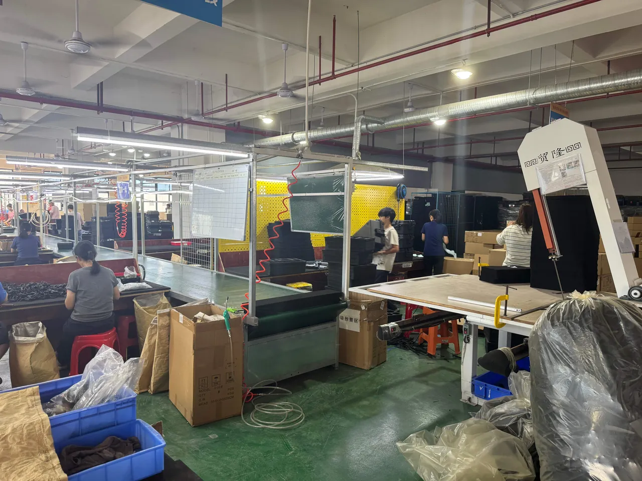
PC became the first choice for transparent protective parts through the combination of three factors.
Factor one: an amorphous structure delivers clarity. PC molecular chains are arranged without order, with no crystalline regions to scatter light, so the bulk is transparent. This contrasts sharply with semi-crystalline materials such as PP and PE, where spherulite dimensions approach the wavelength of visible light and scatter strongly, limiting them to translucency or opacity.
Factor two: molecular structure delivers impact resistance. The combination of carbonate linkages and the rigid bisphenol A backbone gives PC very high notched impact strength at room temperature, and its toughness is relatively insensitive to temperature, staying substantial when cold — something ordinary PS and PMMA lack.
Factor three: dimensional stability. PC has a relatively low coefficient of linear expansion and low water absorption, so dimensions change little with temperature and humidity, helping maintain the flatness of the sealing face.
But PC's three weaknesses must be acknowledged at the design stage:
- Moderate UV resistance. Long outdoor exposure causes yellowing, needing UV absorbers or a protective coating.
- Notch sensitivity. Sharp corners, unpolished edges and machining marks can all become crack initiators, so every internal corner of a clear PC part should be radiused.
- High melt viscosity. Poor flow means higher injection pressure and temperature, and a greater tendency to internal stress and flow marks.
The comparison with PMMA (acrylic) is often confused. PMMA has higher transmittance (up to 92%), higher surface hardness and less yellowing, but far lower impact strength and marked brittleness. For a protective case subject to drops and impact, PC is the more reasonable choice; where the application is mainly static display with almost no impact, PMMA has better optical performance. For material comparison, see PP, ABS and PC compared.
Process Limit One: Wall Thickness versus Transmittance and Haze
Wall thickness is the single most critical variable in transparent-part processing, for three reasons.
First, optical path and accumulated scattering. Absorption and scattering accumulate with the optical path — that is, with wall thickness. The thicker the wall, the lower the transmittance and the higher the haze, a basic law of optics. Empirically, increasing wall thickness from 3 mm to 6 mm can raise haze by several percentage points or more, depending on material purity and process control.
Second, cooling time and optical uniformity. Cooling time scales roughly with the square of wall thickness. A thick part cools slowly and tends to develop internal density variation and residual stress, and density variation itself creates optical non-uniformity through local refractive index differences.
Third, sink marks and depressions. A thick region contracts on cooling and tends to produce surface sink marks, and on a clear part a sink mark is a visible depression and optical distortion that no paint can hide.
Countermeasures:
- Keep wall thickness as uniform as possible. Clear parts above all hate abrupt thickness changes, because a thick region cools slowly and a thin region quickly, generating internal stress and optical distortion. Design for equal wall thickness, with gradual transitions at changes.
- Keep thickness within a sensible band. Small and medium clear parts are commonly 2.5-4.0 mm; above 5 mm, assess optical metrics more cautiously.
- Where necessary, switch to a transparent panel plus structural backing. When structural strength demands a thick wall while optics demand a thin one, let an opaque backing or frame carry the structure and keep the clear part as a thin panel. This is the usual resolution of the two.
| Wall thickness (typical) | Relative transmittance change | Relative haze change | Relative cooling time (approximate) | Process advice |
|---|---|---|---|---|
| --- | --- | --- | --- | --- |
| 2.5 mm | Baseline | Baseline | Baseline | Best optical window |
| 4.0 mm | Slight fall | Rises | About 2.6 times | Requires tight control |
| 6.0 mm | Marked fall | Marked rise | About 5.8 times | Assess a split structure |
| Above 8.0 mm | Significant fall | Significant rise | About 10 times | Consider thermoforming or a split structure |
The figures are empirical estimates based on cooling time scaling with the square of thickness, used to illustrate the trend; actual values must be established by trial moulding with the specific material and process.
Process Limit Two: Flow Marks, Weld Lines and Gate Marks
The defining feature of a clear part is that it exposes every moulding defect. Problems hidden by colour and texture on a dark part all "develop" on a clear one.
Flow marks. Ripple-like traces left by the cooling melt front as it advances through the cavity. Causes include insufficient melt temperature, incorrect injection speed, low mould temperature and undersized gates. On a clear part they appear as concentric ripples or radial streaks.
Weld lines. The interface formed where two melt streams meet in the cavity, with strength and optical performance below the bulk. On a clear part a weld line appears as a visible line or hazy band. Gate position, wall uniformity and flow balance determine its location and count. The design principle is to guide weld lines into invisible or non-optical zones, and to reduce their number by optimizing gate and runner design.
Gate marks. The gate is where melt enters the cavity, and its vicinity tends to show jetting marks, concentrated shear stress and local discolouration. On a clear part a gate mark is usually unavoidable, so place the gate at an edge, behind an assembly feature, or on the base.
Black specks and contamination. Impurities in the resin, degradation products or barrel residue form black specks. Clear parts are close to zero-tolerance for black specks, so resin handling, barrel cleaning and material-change procedures must be stricter than for ordinary parts, and this is a significant source of yield difference.
Countermeasures summarised:
- Raise mould temperature. This markedly improves flow marks and weld lines, at the cost of a longer cycle.
- Optimize the injection speed profile. Use multi-stage injection: slow at first fill to avoid jetting, fast in the middle, and slow at the end to avoid over-packing.
- Optimize gate position and size. The gate should be large enough to avoid excessive shear, and positioned discreetly.
- Manage resin cleanliness. Dedicated barrels, dust-free feeding, and strict material-change cleaning procedures.
Process Limit Three: Internal Stress, Birefringence and Optical Distortion

Internal stress is the most subtle and stubborn problem in clear parts.
Where internal stress comes from. During injection moulding the melt undergoes uneven cooling and shear in the cavity; molecular chains are stretched and oriented and have no time to relax before freezing, leaving frozen orientation and internal stress. Uneven thickness, undersized gates, incorrect packing and low mould temperature all aggravate it.
Birefringence. Oriented molecular chains give the material a different refractive index in different directions — this is birefringence. Its direct manifestation is optical distortion: viewing an object through the clear part shows ghosting, coloured fringes at edges or deformation, especially under polarised light, where it looks like coloured stress fringes.
Three consequences of internal stress:
- Optical distortion, affecting appearance and visibility.
- Stress cracking risk. Internal stress plus an external chemical medium (some cleaning agents, oils) plus a notch can trigger stress cracking, appearing on a clear part as fine cracks.
- Dimensional instability. Internal stress releases on subsequent heating, changing dimensions and hence the flatness of the sealing face.
Detection method. The usual non-destructive method is polarised light observation: place the clear part between two crossed polarising filters and observe the distribution and density of stress fringes. Denser fringes and more vivid colours mean higher internal stress. This is a low-cost, visually direct method well suited to outgoing inspection of clear parts.
Countermeasures:
- Raise mould temperature so molecular chains have longer to relax.
- Raise barrel temperature moderately to improve flow and reduce shear.
- Optimize the packing profile to avoid over-packing.
- Anneal after moulding (hold below the material's softening temperature, then cool slowly) to release residual stress. Annealing is a common post-treatment for clear parts but adds process steps and time.
Process Limit Four: Mould Surface Grade and Polish on Release
Clear parts demand far more of the tool than ordinary parts.
Surface grade determines the finished surface. A moulded part replicates the tool surface. To achieve low haze and high gloss on a clear part, the cavity surface must reach a very high polish grade. The industry commonly describes this using SPI (Society of the Plastics Industry) or VDI surface grades: optical-grade surfaces usually require SPI A1-A2 mirror polishing, whose tool machining time and cost are markedly higher than for an ordinary textured tool.
Tool material and maintenance. High-polish tools usually use cleaner, harder tool steels to reduce pinholes and polishing defects. High-gloss tools are also more easily damaged, demanding stricter daily maintenance — rust prevention, impact protection, polish restoration.
Draft angle and ejection. A clear part surface tolerates no ejector-pin marks or scuffing, so larger draft angles, smoother ejection and finer release-agent management are needed (some optical parts do not permit release agent at all). All of this adds tool complexity and process difficulty.
Cost impact. A high-gloss tool typically costs 30-80% more than an ordinary textured tool of the same size, and lead time may extend if polishing needs rework. For tool cost composition, see custom case mould cost analysis.
Process Limit Five: UV Ageing and Yellowing
PC's weak weatherability is the main limitation of a clear lid in outdoor applications.
The yellowing mechanism. Under the combined action of UV light, oxygen and heat, PC undergoes photo-oxidative degradation: chains break and chromophores form, and the colour shifts from colourless towards pale yellow and then brown-yellow. Yellowing is accompanied by falling transmittance and rising haze, so it is an optical performance problem as well as an appearance one.
Quantification and verification. Yellowing is commonly characterised by the yellowness index (YI), measured with a colorimeter. Weatherability is assessed by artificial accelerated ageing to the ISO 4892 series (methods of exposure of plastics to laboratory light sources), measuring changes in yellowness index, transmittance and haze, and comparing mechanical property retention.
Countermeasures:
- Select a PC grade containing a UV absorber (UVA), the most basic measure.
- Add antioxidants and light stabilisers (HALS) to inhibit the photo-oxidative chain reaction.
- Apply a surface coating or hard coat to block UV at the surface while raising surface hardness and scratch resistance.
- Avoid long-term direct exposure, or use a mounting arrangement with a shading structure.
A realistic trade-off: adding UV additives slightly lowers transmittance and raises cost, and higher grades cost more while performing better. Match the grade to the actual exposure: an indoor or sheltered scenario can use a basic grade; long-term outdoor exposure requires a high-grade or coated solution.
Process Limit Six: Structural Limits — Ribs "Develop"
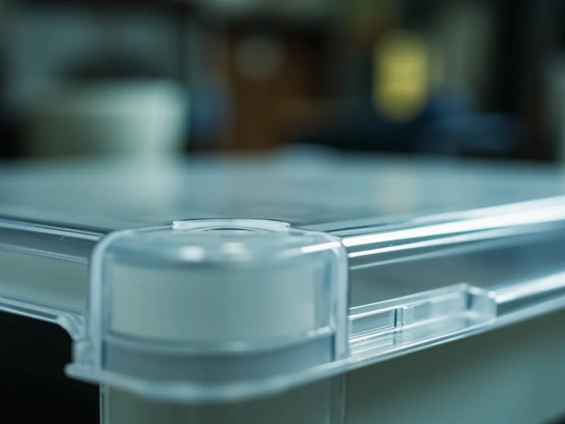
This is the most underestimated limit on clear parts: internal structure that is entirely normal on an opaque part becomes a visible blemish on a clear one.
Ribs develop. A rib creates an abrupt change in refractive index and thickness inside a clear part, visible to the eye as internal striations or optical distortion bands. The thicker and denser the ribs, the more pronounced the development. Sink marks at rib roots are also directly visible on the surface.
Bosses, snaps and internal steps. These likewise appear as visible contours inside the clear part. They also cause local thickness changes that aggravate internal stress and optical distortion.
Three structural design principles:
- Move load-bearing structure to opaque parts. If the lid is clear, place ribs, bosses and hinge seats on the opaque body as far as possible, leaving the clear lid with the minimum structure.
- Use a transparent panel plus opaque frame. Let the opaque frame carry structure, sealing and hinges while the clear panel handles visibility only, joined by clips or screws. This is the most effective resolution of the structure-versus-transparency conflict.
- If ribs are unavoidable, make them shallow and wide and keep them away from optical zones, and treat rib visibility as an appearance acceptance item.
Note that rib design must account for visibility as well as structural necessity. Sound rib principles (rib-to-wall ratio, radii, spacing) are covered in protective case reinforcement ribs. On clear parts these principles must be applied more strictly, while accepting the resulting structural limitation.
Clear Lid and Case Sealing: Shrinkage and Flatness Challenges
A clear lid ultimately mounts to the case and takes part in sealing, which raises two specific difficulties.
Difficulty one: shrinkage difference. If the clear lid and the body use different materials (PC lid with an ABS or PP body, for example), their moulding shrinkage differs. A shrinkage difference causes the rim and lid mating dimensions to mismatch, affecting the uniformity of gasket compression. Countermeasures: prefer the same material, or design separate allowances for each shrinkage and confirm the actual mating dimensions by trial moulding.
Difficulty two: flatness. Sealing depends on the two faces — rim and lid — meeting, so flatness is a critical quality metric for a clear lid. The flatness of a clear part is strongly affected by internal stress and cooling uniformity: warping at thick walls, rib roots and gate areas pushes local sealing faces off position. This is the most common cause of leakage in clear lids. Countermeasures include equal-wall design, uniform cooling, annealing, and positioning the seal groove in a stiffer region.
Gasket matching. Gasket compression and groove dimensions must be re-checked for the clear material's stiffness. PC is stiffer than PP, so at equal compression a PC part generates a greater reaction force, which may require adjusting latch retention. For gasket material and structure matching, see protective case seal materials.
Verification requirement. A case with a clear lid must undergo whole-enclosure ingress protection testing to IEC 60529 / GB/T 4208-2017, with dust and water tests and a re-test after thermal cycling. A single test at ambient temperature is insufficient, because stress release and thermal deformation show up only after cycling. For structural design, see high-strength case structural design.
Transparent Materials Compared: PC, PMMA, PS, PETG and PP
| Material | Transmittance (typical) | Impact resistance | Surface hardness | Weathering / yellowing | Moulding difficulty | Relative cost | Suitable for |
|---|---|---|---|---|---|---|---|
| --- | --- | --- | --- | --- | --- | --- | --- |
| PC (polycarbonate) | 88-90% | Very high | Medium | Medium (needs UVA) | Medium-high | High | Impact-resistant clear lids, windows |
| PMMA (acrylic) | About 92% | Low (brittle) | High | Good | Medium | Medium-high | Static display, low-impact guards |
| PS (polystyrene) | 88-90% | Low (brittle) | Medium-low | Poor | Low | Low | Low-cost clear parts, disposable |
| PETG | About 88% | Medium-high | Medium-low | Good | Low | Medium | Thermoformed trays, clear packaging |
| PP (translucent) | Not applicable (cloudy) | Medium | Low | Medium | Low | Low | Translucent containers, non-optical |
| Optical-grade PC (UVA or coated) | 87-90% | Very high | Medium-high | Good | High | Very high | Outdoor high-clarity high-impact |
Three selection judgements:
- For impact plus clarity, choose PC. This is the standard answer in protective cases.
- For maximum clarity and surface hardness without impact, choose PMMA.
- For low-cost clarity where brittleness is acceptable, PS or PETG — but neither suits a protective case lid.
Test Standards and Verification Methods
Acceptance of a clear lid must cover four categories: optical, mechanical, protection and environmental.
Optical:
- Transmittance, per ISO 13468 (total luminous transmittance of transparent plastics) or ASTM D1003.
- Haze, per ASTM D1003.
- Optical distortion, per the agreed projection, grid or standard-sample visual comparison method.
- Internal stress, by polarised light observation, as an in-process check.
Mechanical:
- Tensile and flexural properties, per ASTM D638 / ASTM D790, to assess the effect of material and process on mechanical performance.
- Notched impact, to assess the notch sensitivity of PC parts.
- Flammability, per UL94 where electrical or fire requirements apply.
Protection:
- Whole-enclosure ingress protection, per IEC 60529 / GB/T 4208-2017, with the clear lid fitted.
- Re-test after thermal cycling, to assess sealing changes from stress release and material deformation.
Environmental:
- Artificial weathering, per the ISO 4892 series, measuring yellowness index, transmittance, haze and mechanical property retention afterwards.
- Salt spray, per ISO 9227, assessing metal fittings and surface coatings.
- Damp heat, in the spirit of MIL-STD-810H Method 507.
An important reminder: optical metrics must be measured on the actual product, not merely on material plaques. Moulding process affects haze and distortion far more than material differences do — the same PC resin can yield a clear part below 3% haze with good processing, or above 15% with poor processing.
Application Scenarios and Selection Advice
Practical judgements by scenario.
Scenario one: a small clear viewing window (to inspect an internal indicator, instrument or label). This is the easiest transparent application. Make it a separate thin-walled window part inserted into an opaque lid, with the structure carried by the lid. This gains visibility while avoiding the process difficulty of a fully clear lid.
Scenario two: a small-to-medium fully clear lid. Feasible, but accept lower yield and higher cost. Recommended: equal wall thickness of 2.5-4.0 mm, SPI A1-A2 polished tool, structure moved to the body where possible, discreet gate, annealing after moulding.
Scenario three: a large clear lid (over 500 mm). Switch to a transparent panel plus opaque frame, or use thick-sheet thermoforming followed by machining, rather than fully injection moulding the lid. Large-part moulding raises both defect risk and tool cost sharply.
Scenario four: high clarity plus high impact plus high flatness. This "triple high" combination typically needs optical-grade PC, a tight process window, annealing and possibly a coating, with the greatest cost and yield pressure. Prototype and verify before committing to production.
Scenario five: translucent or frosted appearance. If the customer accepts a translucent look, process difficulty falls sharply, because once the haze requirement is relaxed, flow marks and weld lines are no longer conspicuous. This is a frequently overlooked practical compromise. For colour and appearance customization logic, see protective case colour customization.
Clear Lid Customization in OEM/ODM Projects
Three things must be settled early in an OEM/ODM clear-lid project.
First, define optical target values. The enquiry must state target values and acceptance methods for transmittance, haze and distortion, or the gap between sample and expectation will erupt at acceptance. It is advisable to provide an "acceptable worst sample" reference.
Second, define the structural and sealing boundary. Clarify which structural features must be on the clear part and which can move to the opaque part; specify the flatness requirement and inspection method for the sealing face; and settle how the shrinkage difference is handled.
Third, define verification scope and cost. Clear parts usually need several trial-moulding rounds (adjusting mould temperature, injection speed, packing and annealing), so prototyping lead time and cost exceed those of ordinary parts. Agree the number of trial rounds and who bears the cost in the contract.
JUNZHJIA, manufactured by KeXin New Materials (Guangdong) Co., Ltd., assesses the feasibility of a clear lid against the customer's optical metrics and structural requirements, providing a complete solution from structural simplification and mould polish grade to moulding process and annealing, and in wholesale, distribution and OEM/ODM projects provides trial-round scheduling and whole-enclosure verification documentation.
Frequently Asked Questions
Q: Is a transparent protective case actually feasible, and why do many manufacturers say it cannot be done? A: It is feasible, but feasibility falls rapidly with size, wall thickness and optical requirement, and that is the real reason many manufacturers decline. There are three hard technical constraints. First, haze rises with wall thickness, so a thick-walled clear part is hard to make crisp. Second, flow marks, weld lines and internal stress are directly visible on a clear part, whereas they are entirely invisible on an opaque one. Third, ribs, bosses and internal steps appear as visible contours inside the clear part while causing thickness changes that aggravate optical distortion. A feasible transparent solution therefore demands four costs: structural simplification (moving load-bearing structure to opaque parts), uniform wall thickness, a higher mould surface grade (SPI A1-A2 mirror polish), and acceptance of lower yield and higher cost. To judge whether a project is worth pursuing, ask three questions first: how large, how thick, and what optical grade. A small viewing window is easiest; a large fully transparent lid should consider a transparent panel plus opaque frame instead.
Q: What material should a transparent protective case use? A: PC (polycarbonate) is the first choice, the best common material combining clarity and high impact resistance. PC is amorphous and optically clear (transmittance typically 88-90%), while its molecular structure gives very high impact strength and retains toughness at low temperature — something ordinary PS and PMMA lack. But PC has three weaknesses that must be acknowledged: moderate UV resistance, with yellowing on long outdoor exposure requiring UV absorbers or a coating; notch sensitivity, so all internal corners should be radiused; and high melt viscosity, meaning poorer flow and a greater tendency to internal stress and flow marks. Where the application sees almost no impact and maximum clarity and surface hardness are wanted, PMMA has better optics (about 92% transmittance) but is markedly brittle and unsuitable for a case lid. PS and PETG are low cost but brittle, generally used for thermoformed trays or clear packaging rather than load-bearing lids. For long outdoor exposure, choose optical-grade PC with UV absorbers or an added hard coat.
Q: Why does a clear part become hazy and develop flow marks and weld lines? A: The causes differ, but the common factor is that these defects are invisible on a dark part and fully exposed on a clear one. Haziness (rising haze) comes mainly from three sources: insufficient resin purity or contamination, accumulated scattering from excessive wall thickness, and internal density variation from uneven cooling. Flow marks are ripples left by the cooling melt front, caused by insufficient melt temperature, incorrect injection speed, low mould temperature and undersized gates. Weld lines form where two melt streams meet, with lower strength and optical performance than the bulk; their position and count are set by gate position, wall uniformity and flow balance. Black specks come from resin contamination, degradation products or barrel residue, to which clear parts are close to zero-tolerant. Four process countermeasures apply: raise mould temperature; optimize the multi-stage injection speed profile; optimize gate position and size; and enforce strict resin cleanliness with dedicated barrels, dust-free feeding and disciplined material changes. Place the gate at an edge or behind an assembly feature to conceal the unavoidable gate mark.
Q: What problems do internal stress and birefringence cause, and how are they detected? A: Internal stress is the most subtle and stubborn problem in clear parts and has three consequences. First, optical distortion: oriented chains give different refractive indices in different directions (birefringence), so viewing through the part shows ghosting, coloured edge fringes or deformation, especially under polarised light. Second, stress cracking risk: internal stress combined with an external chemical medium (some cleaning agents, oils) and a notch can trigger stress cracking, appearing as fine cracks on a clear part. Third, dimensional instability: stress releases on later heating, changing dimensions and hence the flatness of the sealing face — a common cause of leakage in clear lids. For detection, the most practical method is polarised light observation: place the part between two crossed polarising filters and observe the stress fringes; denser, more vivid fringes indicate higher stress. It is low cost and visually direct, well suited to outgoing inspection. Process countermeasures include raising mould and barrel temperature, optimizing the packing profile, and annealing after moulding to release residual stress.
Q: Does a clear lid affect the sealing and waterproofing of a protective case? A: It does, and it must be handled specifically. There are two core difficulties. First, shrinkage difference: if the clear lid and body use different materials (PC lid with an ABS or PP body, for example), differing moulding shrinkage causes the rim and lid mating dimensions to mismatch, affecting uniform gasket compression; prefer the same material, or design separate shrinkage allowances and confirm actual mating dimensions by trial moulding. Second, flatness: sealing depends on the rim and lid faces meeting, and the flatness of a clear part is strongly affected by internal stress and cooling uniformity; warping at thick walls, rib roots and gates pushes local sealing faces off position, and this is the most common cause of leakage in clear lids. Countermeasures include equal-wall design, uniform cooling, annealing, and placing the seal groove in a stiffer region. PC is also stiffer than PP, so at equal compression the reaction force is higher and latch retention may need adjusting. Verification must be whole-enclosure to IEC 60529 / GB/T 4208-2017 with a re-test after thermal cycling, not a single ambient test.
Q: Will a clear PC lid yellow outdoors, and how can it be prevented? A: Yes. Under the combined action of UV light, oxygen and heat, PC undergoes photo-oxidative degradation: chains break and chromophores form, shifting the colour from colourless towards pale yellow and then brown-yellow, with falling transmittance and rising haze, so yellowing is an optical as well as an appearance problem. Yellowing is characterised by the yellowness index (YI) measured with a colorimeter, and weatherability is assessed by artificial accelerated ageing to the ISO 4892 series, measuring changes in yellowness index, transmittance and haze along with mechanical property retention. Four countermeasures: select a PC grade containing a UV absorber (UVA), the most basic measure; add antioxidants and light stabilisers (HALS) to inhibit the photo-oxidative chain reaction; apply a surface coating or hard coat to block UV at the surface while raising hardness and scratch resistance; and avoid long-term direct exposure or use a shading structure. Note the trade-off: UV additives slightly lower transmittance and raise cost, and higher grades cost more, so match the grade to actual exposure — a basic grade suffices indoors or under shelter.
Q: Can ribs really not be used on a clear part? A: They can be used, but their visibility and necessity must both be re-assessed. A rib creates an abrupt change in refractive index and thickness inside a clear part, visible as internal striations or distortion bands; thicker, denser ribs develop more obviously, and sink marks at rib roots are directly visible on the surface. Three design principles follow. First, move load-bearing structure to opaque parts: if the lid is clear, place ribs, bosses and hinge seats on the body as far as possible, leaving the clear lid with minimum structure. Second, use a transparent panel plus opaque frame: let the opaque frame carry structure, sealing and hinges while the clear panel handles visibility only, joined by clips or screws — the most effective resolution. Third, if ribs are unavoidable, make them shallow and wide and keep them away from optical zones, treating rib visibility as an appearance acceptance item. Clear-part ribs must also follow the general principles of rib-to-wall ratio, radii and spacing even more strictly, to avoid sink marks and internal stress.
Q: How much more do a clear lid's tooling and cost run compared with an ordinary part? A: Cost rises in four ways and must be budgeted for. First, mould surface grade: achieving low haze and high gloss usually requires SPI A1-A2 mirror polishing, and a high-gloss tool typically costs 30-80% more than an ordinary textured tool of the same size, with lead time possibly extended by polishing rework. Second, tool material: high-polish tools usually use cleaner, harder tool steels to reduce pinholes and polishing defects. Third, yield: clear parts are close to zero-tolerant of flow marks, black specks and internal stress, demanding stricter resin cleanliness, mould temperature control and process windows, so yield is usually lower than for opaque parts. Fourth, trial rounds: clear parts often need several trial-moulding rounds (adjusting mould temperature, injection speed, packing and annealing), so prototyping cost and lead time exceed those of ordinary parts. Define the optical target values and acceptance method at the enquiry stage, and write the number of trial rounds and who bears the cost into the contract, to avoid disputes at acceptance.
Q: If I only need to see a little of the contents, is there a more economical option? A: Yes, and it is often more economical than a fully clear lid: a localised clear viewing window. Make a separate thin-walled clear part (PC or PMMA) and insert it into a prepared opening in the opaque lid, leaving structure, sealing and hinges with the opaque lid. This has four benefits: the optical requirement concentrates on a very small area, making haze and distortion easier to meet; a thin part cools quickly with low internal stress and good yield; the load-bearing structure is not limited by the clear material's properties; and the cost is markedly lower than a fully clear lid. Three cautions: the window-to-lid joint must be sealed (by gasket, sealant or ultrasonic welding) and must not become a water path; the window should be away from impact and scratch-prone locations; and the shrinkage difference between window and lid materials must be accounted for in design. If the customer accepts a translucent look, relaxing only the haze requirement without going fully transparent makes flow marks and weld lines inconspicuous and reduces process difficulty sharply.
Conclusion and Further Reading
Back to the title question: a protective case can be made transparent, but transparency is not a property you get by switching material — it is a continuous quantity defined jointly by transmittance, haze and optical distortion, and tightly constrained by process. Six process limits — wall thickness, flow and weld marks, internal stress and birefringence, mould surface grade, UV yellowing, and structural development — together set the feasible boundary. A feasible transparent solution usually costs four things: structural simplification, uniform wall thickness, a higher polish grade, and lower yield and higher cost.
Three actionable recommendations: first, quantify before debating feasibility — write target values and acceptance methods for transmittance, haze and distortion into the enquiry, or the sample gap will erupt at acceptance. Second, move load-bearing structure to opaque parts first — a transparent panel plus opaque frame, or a localised window, is usually more economical and reliable than a fully clear lid. Third, treat flatness and whole-enclosure verification as hard metrics — verify to IEC 60529 / GB/T 4208-2017 and re-test after thermal cycling, because leakage from stress release and material deformation usually appears only after cycling.
JUNZHJIA, manufactured by KeXin New Materials (Guangdong) Co., Ltd., supplies protective cases, tool boxes, military-specification storage cases and waterproof junction boxes for wholesale, distribution, OEM/ODM and global supply, assessing the process feasibility of transparent parts and providing optical metric definition, mould polish grade, moulding process and whole-enclosure verification documentation.
Further Reading