

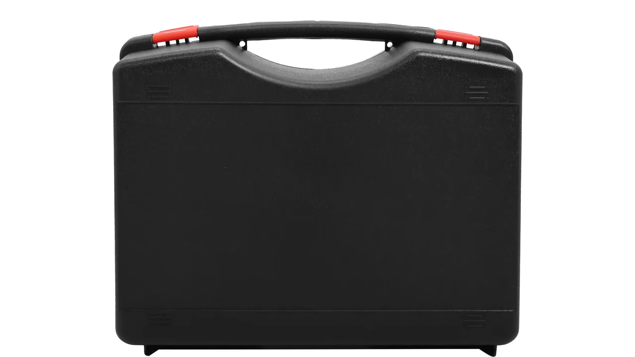
A maintenance window at an underground loading station is often only forty-eight hours long, and the bucket and the conveyor chain for one loader usually have to ship in the same spare-parts batch. The bucket is large, open-mouth upward, and front-heavy; the conveyor chain is long, prone to rust, and must not be bent. Stack both into one generic returnable case and the result is predictable: shell distortion, teeth knocking against each other, and chain links taking permanent set somewhere between the warehouse and the shaft station. Assembly then waits for the next shift's spares.
Real protection is not filling the case; it is redistributing cushioning and sealing along four separate paths — tooth load, link load, moisture path, and dust path. JUNZHIJIA treats the bucket and the conveyor chain as two entirely different load objects with separately engineered liners, then bonds them into one countable transport unit inside a shared shell.
Table of Contents
- Tooth Breakage Criteria on Bucket Lips and Weld-Through Limits
- Side-Plate Stiffener Springback and the Correct Shipping Attitude
- Residual Stress Release at the Discharge Opening and Bucket Welds
- Stress Concentration Sites in Chain Plate Tensile Failure
- Pin and Bushing Clearance plus Anti-Rust Cavity Separation
- Sprocket Pocket Wear and Chain Link Phase Alignment
- Take-Up Travel Limits and Chain Link Quantity Reconciliation
- Chain Corrosion and Lubrication in Saturated Mine Air
- Coal Dust Intrusion Paths Past Case Seals
- Section Count Control for Long Chain Packs
- Explosion-Proof Constraints on Packing Materials
- Foam Gradient and Compartment Load Paths Under Impact
- Arrival Acceptance: Link Count and Tooth Integrity
- Frequently Asked Questions FAQ
- Conclusion and Related Reading
Tooth Breakage Criteria on Bucket Lips and Weld-Through Limits
The cutting edge is the only bucket component that meets rock directly. A set typically carries five to eight teeth, fixed to the lip by bolts or pins. Broken rock, isolated boulders, and leftover roof-bolt stubs in the feed make every tooth absorb local impact far beyond its rated duty. Workshop manuals usually compress the rejection rule into one sentence — tip wear past one third of tooth height — but what actually decides whether a tooth goes back on the machine is cracking in the root transition zone.
| Breakage pattern | Field appearance | Rejection basis | Disposition |
|---|---|---|---|
| --- | --- | --- | --- |
| Tip chunk loss | Front of tooth missing, bright fracture face | Remaining height below 40 % of rated | Replace whole tooth |
| Transverse root crack | Crack crossing the tooth width, coal dust packed in as a black line | Crack depth beyond one third of tooth thickness | Reject, no weld repair |
| Longitudinal root crack | Crack running along the height of the tooth | Rejected in every case | Reject whole tooth |
| Impact cratering | Local collapse, 2 mm or deeper | Hardened layer destroyed | Decide on remaining height |
| Ovalised bolt hole | Hole enlarged by more than 2 mm | Side plate has lost clamping force | Evaluate the side plate too |
| Uniform surface wear | Tooth face thinned evenly | Remaining height above two thirds of rated | Weld build-up permitted |
Weld build-up applies only to wear-type teeth, and the gate is narrow: the base metal is either not hardened or the hardened layer has been worn through, the tooth body carries no crack, and remaining height is still above two thirds of the rated figure. The filler must match the original tooth material — usually high-chromium cast iron or alloy steel — and the repair must be slow-cooled, otherwise the build-up zone cracks on its own. Any field decision of "weld it and watch it" leaves a crack sitting inside the next full-load impact.
The transport duty for teeth is simple: no tooth may knock against another in the case, and no side plate may take a load that bends the root. Each tooth needs its own restraint inside the bucket cavity, with a buffer gap of at least 10 mm between neighbours, and no tooth tip may bear directly on a rigid divider.

Side-Plate Stiffener Springback and the Correct Shipping Attitude
Bucket side plates and the lip are thin-wall welded fabric. Tensile capacity is adequate; bending stiffness is not. What actually fails in transit is the shipping attitude. Stack the bucket inverted with the mouth down and the base of the case above lands on the lip edge line. Set it upright with the mouth up and mine water and dust fall straight into the cavity.
The recommended attitude is mouth facing sideways, bucket body on its side, for three reasons:
- The cavity stops acting as a sump for water and fines, so humidity cannot form a pocket inside the bucket.
- The lip edge line no longer takes a concentrated vertical load, because uniform internal pressure is spread by the side-plate stiffeners.
- The centre of gravity moves from the front lip edge toward the middle of the case, so hoisting needs no counterweight block.
The worst transport exposure for the stiffeners is outward bulging caused by insufficient lateral restraint. The rectangular panels between stiffeners bow outward when no liner supports them, and once the bulge exceeds about 5 % of plate thickness the bucket no longer clears the lift frame after assembly. The liner must therefore carry a continuous strip support between every pair of stiffeners, at least 40 mm wide, producing a soft-base / rigid-strip / soft-face gradient.
Two kinds of deformation must be separated. Elastic bulging recovers on release, so a measurement before assembly settles the question. Plastic bulging means the plate has passed yield and needs separate assessment; it should never be forced back by additional pressure.
Residual Stress Release at the Discharge Opening and Bucket Welds
The discharge opening is the second high-stress zone on a bucket. Rock enters at the feed opening and leaves as a mass at the discharge, so the stream grinds and scours the lower edge of the opening. At maximum lift, bucket self-weight and lift-cylinder force add a bending moment there, so three load types stack in one small region.
Welds usually crack at the weld toe, the boundary between the bead and the parent metal. Coal and rock fines enter the crack, and repeated wet-dry cycling underground extends it through the heat-affected zone. The transport packaging objective at a weld is therefore not load capacity. It is to add no stress and to make sure the weld never becomes a load path.
| Weld location | Dominant failure mode | What packing must guarantee | Common packing error |
|---|---|---|---|
| --- | --- | --- | --- |
| Side plate longitudinal weld | Toe crack extension | Liner never routes load onto the weld line | One solid hard foam pad pressed over the weld |
| Weld repair at lower discharge lip | Impact spalling | Edge line isolated on its own | Sharing a divider with the bucket body |
| Root of the lift lug plate | Tearing | Small dedicated cavity with location limit | Left free, striking other parts in transit |
| Fillet weld at stiffener ends | Corner cracking | Stiffener crowns never loaded by hard parts | Upper case base resting on the stiffener crowns |
The lift lug is another overlooked point. It is the load entry for the lift linkage, and once its holes deform, assembly requires reaming and cutting, which eats directly into lift clearance. The liner should build a small cavity for each lug that registers hole position and limits movement around it, so ovalisation shows up at the loading stage.
Stress Concentration Sites in Chain Plate Tensile Failure
A conveyor chain alternates plates, pins, and bushings, usually at 100 mm or 152 mm pitch. The plate is the primary tensile member, and the pin holes at both ends are the critical feature. As a plate wraps around a sprocket, the hole edge carries combined tensile, bending, and bearing stress, and all three superpose at the hole boundary.
Three locations account for most tensile failures, in descending order of frequency:
- The 45-degree zone off the hole edge, where the bore wall meets the plate face and a crack initiates along the maximum principal direction. Most plate failures start here.
- The ligament between the pin hole and any weight-reduction hole. If a central lightening hole sits off-centre, the remaining ligament is too narrow and the load-bearing section is weakened before service.
- The zone between pin holes at the plate ends. Where the pin hole sits too close to the plate end, the end is drawn out by bearing and shear.
| Plate failure | Criterion | Reuse possible | Correct packing action |
|---|---|---|---|
| --- | --- | --- | --- |
| Single-side crack at hole edge | Crack tracking along the bore wall | No | Replace the link; never mix with intact links in one pack |
| Ovalised hole | Long axis beyond 3 % of pitch | No | Replace the link |
| Crack in the lightening-hole zone | Visible crack at the ligament | No | Replace the link |
| Plastic elongation of the plate | Pitch growth beyond 1 % | No | Replace the link |
| Corrosion pitting | Remaining section thinned beyond 5 % | No | Handle as a corroded link |
| Light surface scoring | Surface-only scratch | Yes, paired with same-batch links only | Bag individually, isolate from rubbing neighbours |
| Whole-chain elongation | Elongation rate beyond 2 % | No, rejected per GB/T 1244 | Replace the chain; never patch by pulling |
Mutual crushing between plates is the main cause of ovalised holes in transit. If a chain is coiled naturally into a case, upper links press their weight through a few contacts onto the pin zones of lower links, and several hundred kilograms of static stack load is enough to ovalise holes over a long haul. A chain must therefore never be shipped coiled. It is packed sectioned, laid out flat.
Pin and Bushing Clearance plus Anti-Rust Cavity Separation
The fit between pin and bushing decides the service life of the whole chain, and these are the components most easily damaged in transport. In service the pin rocks minutely inside the bushing, but no visible clearance is tolerated. The usual fit is a clearance fit in which the difference between pin diameter and bushing bore falls between 0.02 and 0.06 mm. Too tight and the chain gouges the sprocket teeth on engagement. Too loose and load concentrates on the hole edge, which drives hole-edge cracking directly.
Handling damage shows up on the bushing bore wall as a step-shaped press mark. Once assembled, that step becomes a stress concentrator — and it is rarely traceable in the workshop, because the damage happened silently inside the case.
Pins and bushings must therefore be:
- stored in cavities separate from the plates, never loose in the same compartment, because a pin end face resting against a plate hole edge leaves a press mark during vibration;
- segregated so that new-chain pins and used-chain pins never share a case, since mixed wear partners cannot be sorted at acceptance;
- greased on the bore, with exposed faces kept away from hygroscopic cushioning.
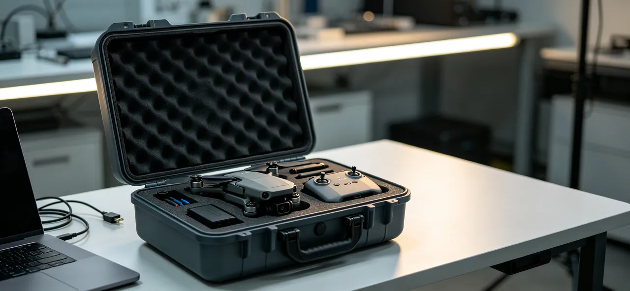
Bore greasing is the step most often dropped. Underground relative humidity sits above 90 % for most of the year, and two weeks of warehouse dwell puts rust spots inside the bushing bores; those spots are only ground to powder after the chain reaches the sprocket. Anti-rust separation means each bushing sits in its own small non-hygroscopic cell formed from closed-cell coated foam or a coated divider sheet.
Sprocket Pocket Wear and Chain Link Phase Alignment
Plates transfer torque by seating their pin holes in sprocket pockets. Tooth flank against plate hole is the only metal-to-metal, high-contact-pressure point in the entire chain. Two wear outcomes matter: a flank that becomes sharp and thin, so the plate is shocked on entry, and a flank that becomes wide, so the plate must swing sideways to seat. Both accelerate hole-edge cracking.
What packing can control is whether links can be re-strung in the correct phase after arrival. If links arrive randomly stacked, the fitter has to pour out dozens or hundreds of plates and reorder them, and the odds of getting the phase wrong are high. A single mis-phased link produces one-sided engagement and eccentric loading.
The working rules are:
- Fold links inside each case into already-strung chain segments and pack the whole segment, rather than shipping loose plates.
- Where loose packing is unavoidable, orient every plate the same way, align the holes, and fix plate positions with dividers.
- Draw three links at random and compare engagement against the sprocket; pocket-to-pin-hole deviation must not exceed 2 degrees.
For used chains, the worn flank is itself the wear datum. Keep old links and their original sprocket together as a set, and never pair new plates with an old sprocket during a maintenance window: the new plates then absorb the entire shock through the first few engagements.
Take-Up Travel Limits and Chain Link Quantity Reconciliation
Underground conveyor take-ups come in screw, hydraulic, and gravity-counterweight forms, and for all three the packing must define the difference between transport state and installed state.
Transport state means the take-up travel is fully released and the chain sits at its natural length inside the case, carrying no elongation. If the chain is constrained at installed length during transit, the plates hold a steady preload; that preload bleeds off slowly over tens of kilometres of road vibration and redistributes itself, and the first links to relax are thrown toward the case wall, striking their hole edges sideways.
| Travel state | Plate loading | Transit risk | Packing action |
|---|---|---|---|
| --- | --- | --- | --- |
| Installed, tensioned | Uniform preload along the chain | Preload relaxation lets links wander | Never pack in this state |
| Transport, natural length | No preload | Local stacking must be prevented | Lay sections flat, limit with dividers |
| Transition during reassembly | Local one-sided load | Pin edge bearing pressure | Bag individual links |
Link quantity must match the design figure. Short delivery means the customer has to splice underground, and there are no welding conditions down there. Over-delivery means the surplus links carry no anti-rust protection and become a corrosion source in the warehouse. The packing list should state design chain length in links, links in this case, and matching pin sets, with pins supplied in the same count.
Chain Corrosion and Lubrication in Saturated Mine Air
Underground roadways hold relative humidity above 90 % for long periods, and both coal faces and development headings drip water onto equipment. Running in that environment, the surface oil film on a chain is displaced by a water film and corrosion starts at the pin hole edge before spreading across the plate. Lubrication failure and corrosion are two faces of one event: lubricant is lost at the next hot surface, the rust layer absorbs water at the next seepage, pitch tightens as rust builds, and the take-up travel is eaten away. The control point is time at temperature and humidity, not the humidity reading itself. Three questions decide whether a chain is at risk:
- Between packing and opening, how many hours did the chain spend at what humidity?
- At opening, is there already a water film or rust spotting on the plate surface?
- Does the warehouse keep temperature and humidity records that can be traced?
The countermeasures run in two layers. Outer layer: shell sealing class is chosen for the actual route, stepped up for long dwell or multiple transhipments, with a humidity indicator card logging the whole route. Inner layer: the chain is treated before packing with heavy-duty anti-rust grease and a wrapping film, and pins and bushings are separated into their own anti-rust cavities. Where a case will sit for a long period in very humid conditions, a desiccant can be added, with the caveat that it works only inside a sealed cavity and is exhausted within weeks once the seal fails; bare metal needs surface treatment and desiccant considered together, because desiccant alone is followed by visible corrosion soon after opening. Humidity and condensation handling in long-dwell scenarios is covered in outdoor case rain and humidity handling.
Coal Dust Intrusion Paths Past Case Seals
In coal and rock dust from underground, the fraction finer than 10 µm is high, and that is what decides the behaviour: the material behaves more like an aerosol than like sand. It can stay suspended, migrate with air movement, and be drawn into gaps whenever a pressure difference appears. Even a case that never sees rain will take dust in after a few rounds of combined vibration and temperature swing, because the fines migrate along seams, hinge gaps, and latch recesses.
Once dust is inside, the damage is not dirt but abrasion. Dust carrying moisture moves in relative motion across a pin hole, which is equivalent to two surfaces being ground by millions of abrasive particles, and the pin-bushing clearance is where this fretting wear concentrates. After installation, the coal dust that entered the cavity gets compacted further in the sprocket and becomes a third-body abrasive in the joint.
Protection along the dust path has three stages:
- Block: continuous gasket runs at every seam rather than intermittent sealing blocks; dust caps or full latch covers over the latch apertures; dust caps on the outer ends of hinge pins.
- Empty: no dead corners inside the cavity that cannot be cleaned; compartment dividers should be removable so the interior can be swept at opening.
- Monitor: a replaceable clean indicator strip, white paper based, sits in the cavity so the colour change at opening reports the intrusion level and sets the disposition for the next shipment.
Dust ingress routes deserve comparison with dustproof design principles for outdoor protective cases, while the adjacent wear mechanisms for mineral handling parts are covered in mining equipment parts cases for crusher and conveyor components.
The most frequently ignored intrusion point is the edge of a compartment divider. A divider merely inserted into foam, without a peripheral seal, lets fines run down the gap into the neighbouring cavity and destroys the whole point of separating pins. Divider edges must be continuously sealed and sit slightly above the compressed foam surface.
Section Count Control for Long Chain Packs
An underground conveyor chain runs tens of metres and weighs tens to hundreds of kilograms, so it has to be broken into sections for packing. Three indicators govern the sectioning: section length, section weight, and the total link count.
Recommended section parameters, shown for 152 mm pitch:
| Parameter | Recommended value | Reason |
|---|---|---|
| --- | --- | --- |
| Section length | 2.0-3.5 m | Longer sections oversize the case and stop the liner conforming; shorter sections multiply the count and complicate counting |
| Section weight | 60 kg maximum | Fits single-person handling and ordinary warehouse rack limits |
| Total length in case | 4.2 m maximum | Simplifies full-truck and container loading |
| Links per case | 3 to 6 | More links force stacking, and the bottom layer carries the load |
| Count margin | Matched 1:1 to design chain length | No welding underground, so a missing link cannot be improvised |
Section length is set by the break point, and the break point must fall on a pin, never in the middle of a plate. A cut through the plate web cannot be rejoined on site and cannot be compensated by adding pins. The preferred approach is the whole-link unit: fold the chain in even numbers of links so that each fold lands exactly on a pin, and the fitter only has to align two pin holes and insert one pin, with no cutting at all.
Where a chain is folded for transport, the inside of the fold is put in bending and the outside in tension, so plate sections inside a fold must be supported by a rigid divider. Without that support a long transit leaves a permanent bend in the folded section, and it will not seat properly in the sprocket afterwards. Every section also carries a weather-resistant label before packing, stating section number, starting and ending pin numbers, length, and link count. Arrival unpacking then follows label order, and the assembly record maps one to one against the label series; once labels are lost, a site ends up with a link count that does not add up and no way to tell which link is absent. Scoring against the machine's vibration exposure is treated separately in shockproof case cushioning structure design.
Explosion-Proof Constraints on Packing Materials
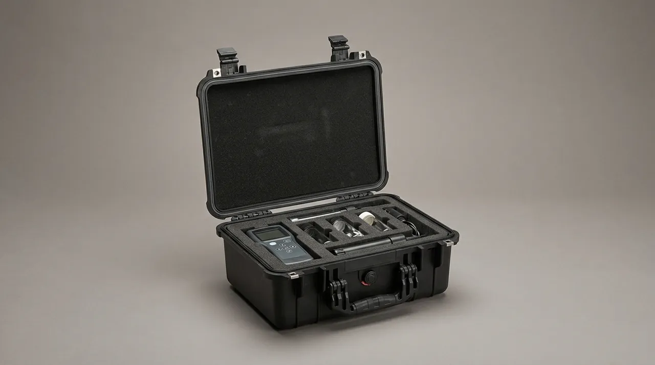
Underground mining equipment operates in a potentially explosive gas atmosphere, so any package that carries electrical items falls inside the explosion-proof compliance boundary. Three constraints govern material selection:
- The equipment itself must hold mining product safety approval, or a mining explosion-proof certificate. That is an entry requirement set by the machine, not by the packaging.
- No non explosion-proof electrical item may appear inside the case. This one is often overlooked. If the case contains a motor, a sensor, a controller, or a cable with a connector, and those parts are not themselves explosion-proof, a strong shell does not make the shipment compliant.
- Packing materials must not become a static or friction ignition source in the underground environment. Many people assume plastic cases are explosion-proof by nature; the real assessment is whether a material produces dangerous frictional heat during handling, whether it accumulates charge, and whether its burning behaviour suits the hazard classification of the location.
The practical conclusions from those constraints:
| Use | Recommended | Not recommended | Reason |
|---|---|---|---|
| --- | --- | --- | --- |
| Cushioning liner | Flame-retardant closed-cell foam selected to the location class | Untreated general EPE | Underground fire load is limited |
| Compartment dividers | Rigid board with flame-retardant coating | Uncoated thin plastic sheet | The divider is part of the load too |
| Seals | Silicone or nitrile rubber gasket | PVC soft strip | Hardens after cooling and ageing |
| Hardware | Stainless steel or zinc-plated steel | Exposed plain carbon steel | Corrosion resistance and strength |
| Labels and printing | Weather-resistant label stock | Ordinary paper labels | Fail quickly at high humidity |
| Desiccant | Packaged silica gel with indicator | Loose unpacked material | Keeps dust out of the cavity |
Explosion-proof constraints feed back into the packing design itself. If a component has to reach the underground but is not certified for that environment, the correct answer is not to wrap it in an explosion-proof case; it is to change the delivery method so non-certified parts never enter the working area. That is a purchasing and technical-agreement decision, not something packaging can resolve. Steel component protection under the same handling regime is covered in rust prevention for metal toolboxes.
Foam Gradient and Compartment Load Paths Under Impact
A bucket filled with rock concentrates momentum at the teeth and lip, and peak impact can reach several times the rated static load. Chain tensile failure is a low-probability, high-consequence event, and once a link parts, the whole section whips inside the conveyor. The case must therefore guarantee that a parted section cannot lash around inside, which means no free movement is permitted between chain links.
The liner uses a three-layer gradient:
- The contact layer, 0 to 8 mm, is soft closed-cell foam cut to the part outline, spreading the local stress of sharp edges over an area. EPE, EVA, or IXPE all work, with density chosen from part mass and target compression.
- The load-bearing layer, 8 to 30 mm, is medium-density foam or moulded closed-cell blocks carrying most of the compression. This layer sets the impact ceiling; softer and thicker is not automatically better, because an over-thick soft layer creeps under stacking.
- The outer support and backing layer spreads load evenly into the shell so the foam cannot channel load into one or two points under impact.
Stacking must work with the liner rather than against it. Once parts and liner are in place, the base of the case above lands on the support layer, not directly on a part or on foam contact skin. Chain sections must never be stacked more than one layer deep and buckets must never be stacked at all; these are hard constraints.
The aim of impact design is not thickness. The requirement is that foam thickness after compaction falls inside the available travel. For a typical free-drop duty, allowable acceleration usually falls in the 25 to 60 g band, varying with case mass and drop height, while allowable foam compression is roughly 25 to 35 % of original thickness; together these set the thickness. Roller and drive component protection is compared in conveyor roller and parts cases.
Arrival Acceptance: Link Count and Tooth Integrity
The first rule of arrival acceptance is record before opening. The shell condition prior to opening is the only evidence that distinguishes transport damage from handling damage at the site.
| No. | Check item | Method | Acceptance criterion | Disposition on failure |
|---|---|---|---|---|
| --- | --- | --- | --- | --- |
| 1 | Shell condition and latches | Visual and manual | No cracks, no distortion, latches complete and lockable | Refuse delivery or photograph as evidence |
| 2 | Water ingress traces | Visual and humidity card | No water marks, card not beyond limit | Record and re-inspect after opening |
| 3 | Gaskets and valves | Visual | Gaskets continuously seated, valves not blocked | Replace before reuse |
| 4 | Bucket teeth | Count and inspect after opening | Complete count, no broken teeth, no cracks | Refill or replace whole teeth |
| 5 | Bucket lip and discharge opening | Visual and tactile | No plastic deformation, no weld cracks | Assess separately, no direct fitting |
| 6 | Total link count and pitch | Count by label, sample pitch | Count matches list, pitch deviation within tolerance | Short shipment sent separately |
| 7 | Pins and bushings | Reconcile count and fit by cavity | Counts matched, no press marks on bores | Replace damaged parts |
| 8 | Plate holes | Sample or full inspection | No cracks, no ovalisation | Reject the link |
| 9 | Liner condition | Visual and rebound check | No collapse, no tearing, no gaps at contact faces | Replace modules locally |
| 10 | Accompanying documents | Check against list | Packing list and certificates complete | Supply before sign-off |
Item 6 is where this shipment most often goes wrong. When links are packed in label order, counting is a matter of reading a label and adding links up. With loose packing, counting becomes pouring everything out and counting, which is itself a second damage event. The most likely counting error is not a lost link but a folded section mistaken for two separate sections. The pin on the inside of a fold is often hidden by the label, so reconciliation must follow the label sequence rather than visual segments.
Conclusions belong in both the packing record and the opening record, with each discrepancy closed out in writing. Whole-chain elongation, critical bucket dimensions, and weld condition deserve photographic records, because those criteria cannot be reproduced before the next shipment. Comparable handling constraints for attachment parts are summarised in excavator parts cases for bucket and cylinder components.
Frequently Asked Questions FAQ
Q: Can an underground bucket and its conveyor chain travel in the same protective case?
A: Yes, but mixing them without compartmentation is not recommended. The two parts fail in completely different ways and need different protection. The bucket is a rigid thick-wall fabrication whose main transit threats are collision in the shipping attitude, teeth knocking together, and added stress on welds. The conveyor chain is a long flexible member whose main threats are ovalisation of plate holes, press marks and corrosion inside bushings, and the hard requirements of no stacking, no coiling, and no preload. If you must combine them, at least three things matter. Chain sections lie flat in a dedicated cavity that shares no load path with the bucket. The bucket lies on its side with each tooth independently restrained, so nothing strikes anything during vibration. And no free movement is left between the two parts, because a wandering link will find the lip edge. Separate cases are the better answer: one case for the bucket, and the chain split into small cases of three to six sections each, keeping case weight controlled, counting simple, and shipments orderable against the repair sequence.
Q: Can a broken bucket tooth be welded back on and returned to service?
A: Only wear-type teeth may be rebuilt; impact-damaged and cracked teeth are rejected outright. The dividing line is remaining height and base-metal condition. All three conditions must hold together: remaining tooth height at or above two thirds of the rated figure, the surface worn evenly rather than chunked away locally, and no detectable crack in the root or body. If any one fails, the tooth is replaced whole. The rebuild itself needs matched filler and controlled cooling, so a high-chromium cast-iron tooth takes a matching alloy consumable and a slow-cool cycle to stop the build-up zone from cracking open on its own. The transport duty is to keep that rebuild zone unloaded, so teeth are individually restrained whether or not they were welded, with at least 10 mm of buffer gap between tips and no tip bearing on a rigid divider. Many rebuilds fail on the very first bucket load, and the cause is rarely the weld. It is packing that leaves tips jammed against each other, so all transport vibration ends up concentrated in the weld toe.
Q: Why do chain plates come out of the case with ovalised pin holes?
A: Ovalisation is almost always caused by stack crushing rather than impact. A chain's natural form is coiled, so if it is packed coiled, the weight of upper links passes through a few contacts into the pin zones of lower links. With rocking and vibration in transit, that static load cycles repeatedly and the holes deform slightly under continuous squeeze, and the deformation grows with distance travelled. The fix is to stop coiling. Break the chain into sections at the design length, fold each section, and lay them flat in separate cavities with one layer only. Where stacking is unavoidable, the lower cavity needs a rigid divider that spreads the load across a whole panel instead of letting it hang on a few links. It also helps to orient every plate the same way and to fix plate positions with dividers, so a folded section cannot drift onto its neighbours. At acceptance, sample pitch and hole long-axis; a long-axis deviation beyond 3 % of pitch rejects that link outright, and neither reaming the hole nor fitting a new pin makes it serviceable again, because the surrounding plate has already lost its bearing area.
Q: Does explosion-proof requirement restrict what the protective case may be made from?
A: It does, and the boundary is worth stating clearly. The explosion-proof status of underground equipment is decided by the equipment itself and evidenced by mining product safety approval or a mining explosion-proof certificate, which packaging cannot confer. What packaging management must cover is two things. First, no non explosion-proof electrical item may travel in the case: motors, controllers, sensors, and cable bundles with connector heads each need their own approval or must be excluded from underground use. Second, packing materials must not become a friction or static ignition source during handling, so cushioning foam and compartment dividers are specified as flame-retardant closed-cell materials matched to the location class, with flame-retardant grade documentation retained. Gaskets are specified as silicone or nitrile rather than soft PVC, and hardware as stainless or zinc-plated steel, since exposed carbon steel both corrodes and abrades. It is worth restating that wrapping a non-certified part in an explosion-proof case changes nothing about that part; the correct move is to keep it out of the underground working area through delivery routing and installation planning. Related constraints for hydraulic assemblies appear in hydraulic and pneumatic system case protection.
Q: Chains stored two weeks in the warehouse start to rust; what changes on the packing side?
A: First establish where the rust originates. Rust only on plate surfaces points to ambient humidity and condensation. Rust starting at pin hole edges and inside bushing bores means the cavity ran at high humidity and lacked an anti-rust isolation layer. Three packing changes help. Before packing, coat the chain in heavy-duty anti-rust grease and wrap it, with a mechanical isolation layer outside the film so cushioning cannot rupture it. Separate pins and bushings into dedicated anti-rust cells so they neither share a cavity with the plates nor touch hygroscopic foam. And add packaged silica desiccant with a humidity indicator card to record the whole route, stepped up to a higher shell sealing class for long dwell or multiple transhipments. Keep the desiccant limit in mind: it works only inside a properly sealed cavity and is exhausted quickly once the seal fails. If the indicator card is beyond limit at opening, treat the contents as damp even when the shell looks perfect, dry before assembly, and never fit the chain straight from that state. Bare metal in a sealed case also abrades rather than wears, so press marks inside bores are a packing result and not a handling accident.
Q: What is the ideal section length when a long chain must be broken into packs?
A: For a 152 mm pitch conveyor chain, sections of 2.0 to 3.5 m with a section weight of 60 kg or less, three to six sections per case, and total length held under 4.2 m, balances case size, manual handling, and counting difficulty. Chains of other pitches convert by actual link count; the binding constraints stay the same, namely section weight and the prohibition on stacking inside the case. Break points must land on pins, never in the plate web, because there are no welding conditions on site and a web cut simply cannot be rejoined. The whole-link unit is the preferred method: fold in even link counts so each fold falls on a pin, and the fitter only aligns two holes and inserts one pin, with no cutting. The fold region needs a rigid divider underneath, since the inside of the fold sees bending and the outside sees tension; without support a long transit leaves a permanent curvature that spoils sprocket seating. Labels carrying section number, pin range, length, and link count make arrival counting a sequence check instead of a guessing game.
Q: Do bare metal parts such as bucket teeth and pins need separate packing?
A: Yes, and it is the step most often dropped. Bare metal inside a sealed case does not fail by wear; it fails by fretting and corrosion. Dust and moisture in relative motion across a fitted surface act as two surfaces ground by a very large abrasive population, and step-shaped press marks appear inside bushing bores. Once assembled those marks are stress concentrators, and the damage happened after packing rather than before it. The working rules: restrain each tooth individually with tip-to-tip buffer gaps, store pins and bushings in cavities of their own away from the plates, never mix wear partners of different vintages, grease bushing bores, and put an isolation layer between hardware and hygroscopic cushioning. Acceptance inspection must specifically look inside bushing bores and at pin end faces, because those are the locations where damage accumulates quietly; a clean exterior does not mean an acceptable interior. This mirrors the general approach used for metal toolboxes, covered in rust on a metal toolbox and how to prevent it.
Q: What else does the packaging need to handle between the warehouse and the underground face?
A: Three route points are commonly missed. Loading and transhipment: buckets travel on their side, never inverted or stacked, chain cases must not share a tier with heavy goods, stack height must not exceed the case marking, and the base of the upper case must land on the support layer rather than on a part. Intermediate dwell: at humid or exposed stops, confirm gaskets and equalisation valves are sound and desiccant is live, and during long dwell run a seal and humidity check rather than finding faults at opening. Opening and reassembly: photograph the shell and read the humidity card before breaking the seal, count chain sections in label order, then begin assembly, keeping count and assembly records together. Plan the sequence against the repair window so first-needed sections are not buried under last-needed ones. With no welding underground, assembly quality cannot be fixed on site, so each route record is the last line of defence.
Conclusion and Related Reading
Bucket and conveyor chain transport protection moves underground humidity, dust, impact, and explosion-proof constraints ahead of schedule into packaging. JUNZHIJIA designs liners and compartments around each part's load path, with mould development, OEM/ODM, and case documents supplied by Kexin New Materials (Guangdong) Co., Ltd.
Related Reading