

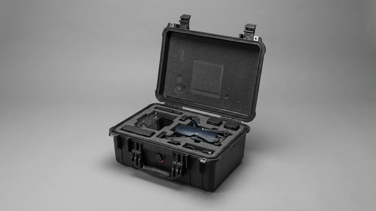
In a modern vehicle test centre the same measurement chain travels between benches all week. Today it captures torsional vibration on a powertrain dynamometer, tomorrow it measures interior noise in a semi-anechoic chamber, then it rides a sled rig for crash-pulse work, and later it runs a road-load campaign or sits in an EMC chamber. Triaxial accelerometers, load cells, strain-gauge channels, signal-conditioning modules and DAQ front-ends are repeatedly dismounted, packed, transported, unpacked and recalibrated. One knock, one electrostatic discharge or one damp night can strip an entire campaign of comparability. The expensive item was never the case; it was the contaminated calibration chain and the delayed test window.
JUNZHIJIA's position: protection for transducers and data-acquisition hardware must be engineered around a measuring instrument, not a generic tool. Every cushioning parameter, every electrostatic drain path and every serial-number label should trace back to a specific sensor model and its sensitivity certificate, so that accurate on arrival and accurate on return becomes a repeatable procedure rather than luck.
Table of Contents
- Why Bench Sensors Need a Purpose-Built Transit Case
- Failure Modes and Countermeasures at a Glance
- NVH Accelerometers: Protection from Mounting to Storage
- Load Cells and Strain-Gauge Channels: Preserving Zero and Sensitivity
- Protecting DAQ Front-Ends and Signal-Conditioning Modules
- Cable, Connector and Adapter Stowage Engineering
- Liner Materials Compared: EPE, EVA, IXPE and PU
- Cushion Design: Matching Static Stress to Cushion Curves
- Temperature and Humidity Limits for Piezo and Strain Transducers
- ESD and Ground Continuity: Do Not Let Static Ruin a Calibration
- Case Structure: Seals, Latches, Stacking and Pressure-Equalisation Valves
- Serial-Number Traceability, Labelling and Travelling Documents
- Acceptance Criteria and Re-Verification Intervals
- Frequently Asked Questions FAQ
- Conclusion and Related Reading
Why Bench Sensors Need a Purpose-Built Transit Case
Bench measurement differs fundamentally from workshop repair. A workshop asks whether something still works; a test laboratory asks whether the data can still be compared. A triaxial accelerometer rated at 100 mV/g leaves the factory with a certificate showing a reference sensitivity of 101.3 mV/g and a transverse sensitivity ratio of 2.1 percent. If a rigid liner point bruises the housing near the sensing element during a move, or a connector pin is bent by the unsupported weight of a cable, that sensitivity can drift past 103 mV/g. Channel gain and calibration factor are unchanged, yet every spectral amplitude is now offset by roughly 1.7 percent, enough to reverse the conclusion of an A/B comparison.
So the case is not a box that holds things; it is a mobile workstation that preserves metrological state through transport and storage. It must keep mounting-face flatness, connector pin concentricity, the orientation memory of a sensing axis and the unbroken pairing between a certificate and the item it describes.
Transfer paths fall into three categories. Short moves inside one laboratory, from the metrology room to the chamber, mainly risk handling knocks, so compartmentation, positive location and one-item-one-slot discipline matter most. Cross-building campus moves pass through goods lifts, service trenches and ramps, adding trolley vibration and brief rain, so cushioning, sealing and wheels dominate. Cross-region field campaigns involve long highway transport and repeated loading, making stacking strength, pressure equalisation, thermal tolerance and asset tracking decisive. Grading every case at IP67 is as wrong as sending a freshly calibrated load cell to a proving ground in a soft bag.
Failure Modes and Countermeasures at a Glance
Before choosing materials, list the failure modes that actually occur on a bench chain. Protection design does not reduce risk to zero; it maps each risk onto a structural feature that can be inspected and accepted.
| Failure mode | Countermeasure | Verifiable feature |
|---|---|---|
| --- | --- | --- |
| Sensitivity drift from impact | Contoured recess plus verified cushion thickness | Recalibration within tolerance after drop test |
| Connector pin deformation | Dedicated connector nests, cable decoupling | Insertion force and contact resistance |
| Broken strain-gauge lead | Retention clips every 80 to 120 mm, bend radius at least 40 mm | Bridge and insulation resistance |
| Dust and oil mist ingress | Gasket, desiccant, periodic seal check | IP grade and dew point |
| ESD puncture of a front-end input | Dissipative liner plus ground terminal | Surface resistance and continuity |
| Thread and mounting-face corrosion | Anti-corrosion treatment, guarded storage | Torque and flatness after salt spray |
| Adhesive cracking after thermal cycles | Temperature-rated liner, five-cycle validation | Seal and liner re-check after cycling |
| Wrong model taken from a shared case | Compartmentation, QR codes, packing list | Scan verification and inventory record |
Every entry in the third column belongs in the purchase specification as a measurable line item. A case that enters a laboratory is managed as part of the metrology system, so its acceptance language must match metrology language rather than a vague claim of good protection.
NVH Accelerometers: Protection from Mounting to Storage
NVH work is the most accelerometer-intensive activity in vehicle testing. One pass-by or interior-noise campaign may run 20 to 40 channels, mixing triaxial ICP units, charge-mode sensors and a few high-temperature types. They share a small body, a high unit price, a fixed calibration interval and a mounting method that depends entirely on a machined face and controlled torque.
Protecting the mounting face comes first. Most piezoelectric accelerometers use a lapped base against an M3 or M5 stud or an adhesive pad. A dent or burr picked up from a hard liner lowers installed coupling stiffness, which shows up as a displaced or amplitude-anomalous mounting resonance at high frequency. Contact between liner and base should therefore be area support rather than point support: contour-matched EVA or low-density PU beneath the base, 1 to 2 mm of lateral clearance, and a light foam compression layer above so the unit cannot shift when the case is inverted.
Protecting the connector comes second. The centre pin of a 10-32 coaxial or M5 micro connector measures only 0.4 to 0.9 mm, and a cable swinging inside the case applies repeated lateral bending to it. Give every transducer its own nest plus an adjacent cable retention position, and always remove cable before transducer, packing in reverse order. Coil radius should be at least ten times the cable outer diameter, so 30 to 40 mm for a 3 mm coaxial lead, which protects the shield from fatigue.
Layout should mirror test-point numbering. A 32-channel vehicle case might be split into front bay, middle row, rear row and exterior groups of eight, each ordered X, Y and Z, so technicians work group by group from the channel list.
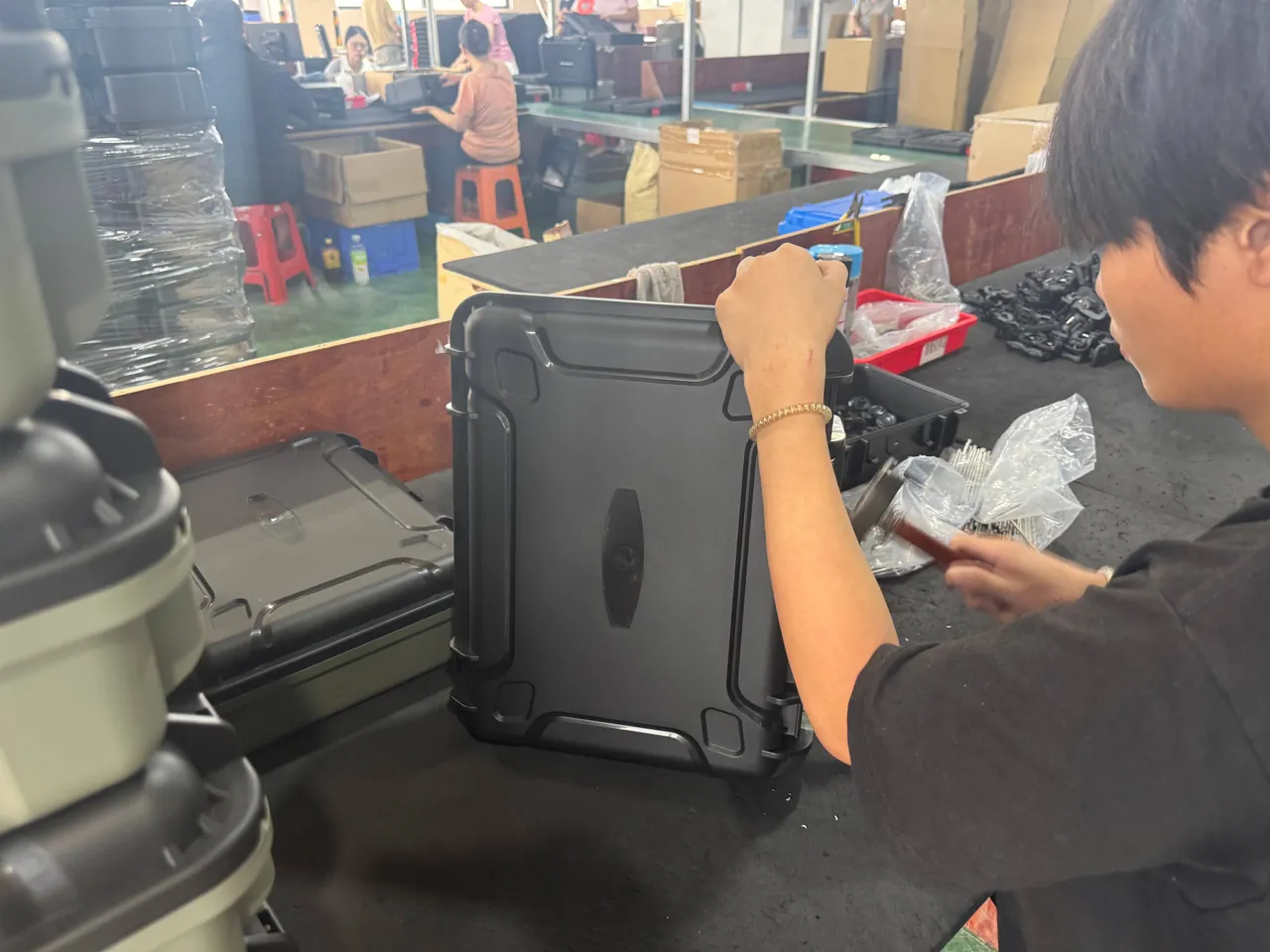
High-temperature accelerometers need one extra measure. Their mineral-insulated or glass-braided cables are thick and stiff, so they should not share a shallow groove with small coaxial leads. Give them a dedicated deep groove of matching width with a soft edge guard against chafing.
Load Cells and Strain-Gauge Channels: Preserving Zero and Sensitivity
Load cells and strain-gauge channels face a different risk profile. For a load cell the central issue is the load history of the elastic body; for a strain channel it is the integrity of the bridge and its leads.
The main hazard in transporting a load cell, whether piezoelectric or strain-gauge based, is eccentric loading and preload along a non-measuring direction. A 10 kN strain-gauge cell resting for months with a few hundred newtons of side load on the sensing beam can develop a zero offset. Its nest must therefore decouple the measuring axis from the gravity axis: stand the cell upright so the housing carries the reaction rather than the beam, or lay it horizontally with support blocks under both flanges so the beam never spans unsupported. After installation, verify zero return within 0.05 percent of full scale and preload torque to the manufacturer's value.
Strain-gauge protection depends heavily on cable management. In quarter-bridge or half-bridge wiring the leads are often only 0.3 to 0.6 mm², and the three-wire runs between active and compensation gauges break easily under repeated coiling. Practical, verifiable measures are a separate elastic retention clip every 80 to 120 mm so no local stress concentration develops, formed storage hooks or winding posts of at least 25 mm diameter, a dedicated nest for bridge boxes and terminal blocks that never shares a recess with a transducer body, and transparent dust caps over terminals to keep metal swarf and oil mist out. Combined with a bridge resistance tolerance of plus or minus 0.5 ohm and an insulation resistance check, these measures turn the question of whether the chain will work on return into a short, measurable checklist.
Protecting DAQ Front-Ends and Signal-Conditioning Modules
The DAQ front-end is the most delicate element in the chain. A typical modular system accepts four to eight conditioning cards in one chassis, each carrying constant-current excitation, anti-alias filtering, a 24-bit converter and isolation. Mechanical shock tolerance is modest; most datasheets quote non-operating limits of 30 g to 50 g half-sine at 6 to 11 ms, and the modules are also sensitive to supply ripple and DC offset.
Compartmentation and damping are the core measures. Place the front-end in a discrete chamber on the hinge side, where the shell is stiffest, and add a 6 to 10 mm EVA pad under the chamber floor to lower contact stiffness and cut transmissibility above 100 Hz. Keep the designed peak acceleration entering that chamber below 20 g. Fan-cooled chassis need at least 30 mm of unobstructed space on the intake side, and you must choose between ventilation and sealing during storage: a sealed case with desiccant, or an open ventilated case, never a sealed case that still expects fan airflow.
Interface protection needs redundancy. D-SUB, RJ45, LEMO and BNC panel connectors sit on the front face and are the first parts struck by a lid or liner. The liner on that side must be recessed with at least 8 mm of clearance, and no hard accessory may be stored in the recess. Power and communication accessories need fixed positions too, because a 24 V supply, an Ethernet switch, a fibre transceiver and a sync clock line are essential on the bench and easily scattered on site. Grouping them into an accessory layer separated from the transducer layer prevents arriving without a synchronisation cable. Before the system leaves the laboratory, short the inputs and record noise floor and zero offset on the travelling card, then repeat the reading before connecting anything after transport.
Cable, Connector and Adapter Stowage Engineering
Cable is the most neglected and most quietly damaging element in a protection case. A typical vehicle kit mixes low-noise coaxial leads with BNC, 10-32 and SMB interfaces, miniature push-pull multi-pin connectors such as LEMO, ODU and Hirose, shielded twisted pairs for strain and thermocouple channels, and power or communication cable for 12 and 24 V supply, CAN, Ethernet and fibre. None of these can be handled by throwing them into one large compartment.
Three hard rules do most of the work. First, never leave a connector unsupported. Every connector must sit in a well deep enough that the well wall carries the cable weight, leaving the pins free of axial and radial load; a LEMO or ODU well should be at least 12 mm deep and about 1 mm wider than the connector body. Second, never lay cable across a hard item. Put a soft divider between cable and transducer bodies so vibration does not turn the lead into a saw, and keep coil radii at 30 mm for 3 mm coaxial, 60 mm for 6 mm multi-core shielded and 40 mm or more for fibre patch cords, which must never be bent sharply. Third, label similar connectors separately. LEMO sizes look alike but key differently, and mixing them forces trial-and-error insertion on site; colour-coded heat-shrink by size is the cheapest error-proofing available.
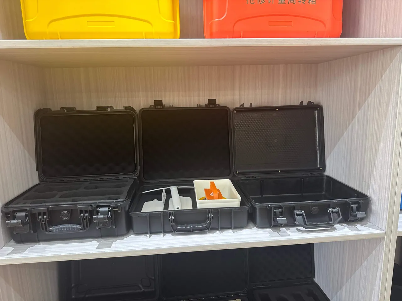
For cross-region teams, add a small cable bag holding only the patch leads needed for the day. The main case stays at the depot, so mud and oil from a vehicle test never reach the primary liner, and liner cleanliness is far easier to maintain.
Liner Materials Compared: EPE, EVA, IXPE and PU
The liner decides whether a case truly fits a transducer, a small, high-value item with precision interfaces. The four common materials behave very differently in bench measurement service, so compare static stress, resilience, cleanliness and machinability together.
| Material | Density (kg/m³) | Static stress at 25 percent compression | Best use |
|---|---|---|---|
| --- | --- | --- | --- |
| EPE, expanded polyethylene | 25 to 35 | 45 to 90 kPa | Large support areas and shell lining |
| EVA, ethylene-vinyl acetate | 40 to 80 | 120 to 320 kPa | Transducer contour recesses, precision location |
| IXPE, irradiated cross-linked PE | 30 to 60 | 70 to 180 kPa | Thin isolation and surface protection layers |
| PU, polyurethane foam | 20 to 45 | 8 to 40 kPa | High-frequency damping pads, soft compression layers |
Four principles follow. Use EVA for transducer contour recesses, because its hardness creates a stable location boundary and carved recesses keep their dimensions instead of collapsing under the payload; for accelerometers and load cells under 200 g, EVA at 40 to 60 kg/m³ is a balanced choice. Use EPE for large shell areas and dividing walls, since its cushion curve is gentle, it absorbs energy efficiently in the 3.5 to 7 kPa static-stress band and it is closed-cell and non-wicking, which matters at humid proving grounds. Use IXPE or PU thin layers for micro-vibration and surface protection, because road transport always brings broadband vibration from 20 to 200 Hz, and a 3 to 5 mm layer between recess and transducer suppresses fretting wear and mirror scratches. Finally, avoid a single-material answer: an all-EPE liner leaves soft recess boundaries and lets transducers shift, while an all-EVA liner is too stiff and transmits more shock energy into the payload. The mature approach is a three-layer composite of outer EPE support, middle EVA location and inner IXPE or PU contact. For a systematic comparison method, see Foam Material Comparison and Case Internal Foam Types.
Cushion Design: Matching Static Stress to Cushion Curves
Cushion design is often reduced to making the foam thicker. In real engineering the thickness and contact area must match the fragility factor of the payload, otherwise thicker foam only adds volume and worsens location stability.
The method has four steps. First, establish fragility. Transducers rarely publish a fragility value, so derive it from the non-operating shock limit. If an accelerometer is rated to 5000 g half-sine at 0.5 ms and a DAQ front-end to 40 g at 11 ms, the design target follows the stricter figure with a safety factor of 1.5 to 2, keeping transmitted peak acceleration below 20 g.
Second, estimate static stress. Static stress equals payload weight divided by bearing area. A 120 g accelerometer resting on a 60 mm by 60 mm EVA pad sees only about 0.33 kPa, far below the useful range of EVA, so the foam barely deforms and locates without cushioning. For light, small items, cushioning must come from the outer EPE and the shell, while the inner material only locates and prevents abrasion. Many designs fail exactly here.
Third, select thickness from the cushion curve. With EPE at 25 kg/m³ and a 20 g target, an 800 mm drop calls for roughly 30 to 45 mm, while 1200 mm calls for 45 to 60 mm. The benefit is not linear, because once a cushion fully compresses it transmits shock directly, producing bottoming out.
Fourth, verify by test. Run whole-case drop and vibration tests against the GB/T 4857 series, ISTA or ASTM D4169, place a triaxial recorder inside the front-end chamber and compare measured peak acceleration and pulse duration with the step-one target; see Transport Vibration Testing. Design to the worst realistic handling event rather than the average, because third-party freight routinely produces throws above 1.2 m.
Temperature and Humidity Limits for Piezo and Strain Transducers
Temperature and humidity affect the measurement chain twice over: they alter transducer performance and they age the liner, seals and labels.
Piezoelectric accelerometers use PZT ceramics whose Curie temperature sits far above the operating range, but the internal charge amplifier and clamping structure set the practical ceiling. Typical industrial ICP units cover -50 °C to +120 °C, while high-temperature versions reach +250 °C and above. Distinguish operating from storage ratings: storage limits are usually 20 °C to 50 °C higher, yet prolonged storage near the upper limit accelerates ageing of internal bonding layers, so keep long-term storage at least 20 °C below the rated maximum.
Strain-gauge sensors are more thermally sensitive, because zero drift relates directly to the thermal expansion of the elastic body. With a 350 ohm bridge, a 10 °C change produces a residual zero shift of roughly 0.01 to 0.03 percent of full scale after compensation. Bringing a sensor straight from a cold site into a 25 °C room and calibrating immediately therefore yields a wrong zero. Let it stand for two to four hours after unpacking, extended to six hours for heavy load cells and torque transducers, and record the start of the stabilisation period on the travelling card.
Humidity needs control at two stages. Condensation appears the moment a cold case enters a warm, damp room because its surface is below the dew point; an optional pressure-equalisation valve equalises internal pressure slowly without admitting liquid water, as described in Pressure Equalisation Valve. For storage, a sealed case should hold replaceable desiccant, roughly 20 to 30 g of silica gel per 10 litres, plus an indicator card that triggers replacement above 40 percent relative humidity. Validate the whole selection with five cycles from -20 °C to +60 °C and re-check seal, liner and sensitivity afterwards, following High and Low Temperature Testing.
ESD and Ground Continuity: Do Not Let Static Ruin a Calibration
Static electricity is the most underrated risk in laboratory protection. Winter relative humidity can fall to 20 percent, and a technician walking across a carpet can charge to 8 to 15 kV. One discharge into a front-panel interface or a connector pin can puncture the gate oxide of an input MOSFET, causing channel drift or permanent failure. The damage rarely appears as an immediate error; it appears as a raised noise floor and distorted low-amplitude signals, which are much harder to detect.
The electrostatic properties of the liner must be specified, not assumed. Dissipative materials have surface resistance between 1 x 10^4 and 1 x 10^9 ohm and suit transducers and DAQ front-ends, because charge drains slowly enough that no high potential builds and no secondary discharge occurs. Conductive materials sit between 1 x 10^3 and 1 x 10^5 ohm and are used mainly for handling trays and direct component contact. Standard EVA and EPE are insulators whose surface resistance can exceed 1 x 10^13 ohm, so they accumulate substantial charge in dry conditions; never support static-sensitive devices directly on plain EVA. Use carbon-black-loaded EVA or EPE, usually dark in colour, or laminate a conductive fabric onto the liner surface.
Ground continuity must also be verified. A well-designed case has an electrically continuous metal frame, hinges and latches, with paint that does not block the conductive path; a dedicated internal ground terminal bonded to the laboratory earth bar by an external braid of at least 4 mm² kept as short as possible; and a continuous drain path from liner to shell, measured at no more than 1 x 10^9 ohm from terminal to the furthest point of the liner. Make this a quarterly check recorded in the case history card, using standard electrodes and a high-resistance meter with criteria aligned to the thinking of ANSI/ESDA S20.20, and add a detachable ground braid and antistatic gloves to every field kit.
Case Structure: Seals, Latches, Stacking and Pressure-Equalisation Valves
The shell sets the ceiling on protection. Test equipment cases usually serve as both transport packaging and long-term storage, so structure must balance sealing, access convenience and stacking strength.
Grade sealing by scenario rather than maximising it. Movement inside one laboratory needs only IP54, because dust protection suffices and there is no spray requirement; cross-building campus moves suit IP65 against brief rain and hose-down; cross-region road transport needs IP67 against temporary immersion and road spray, together with a pressure-equalisation valve; and long-term laboratory storage suits IP65 plus desiccant, where moisture control matters more than water. A temporary position beside an engine bench calls for IP65 with an oil-resistant, replaceable liner.
Latches and hinges drive cycle life. For cases opened more than four times a day, specify cam latches with secondary locking and a visual mis-close indicator, and prefer hinges with metal pins and self-lubricating bushings rated for at least 50,000 cycles. Above 15 kg of contents, distribute hinges over at least three positions so one-sided loading cannot twist the shell and lift the gasket locally.
Stacking strength is a hard field requirement. Calculate the load as unit weight times stacked layers times a safety factor of 1.5. A 40 kg case stacked three high puts about 180 kg of sustained load on the bottom unit, which calls for a ribbed lid and reinforced base verified by a 24-hour static test as described in Stacking Load Test for Cases. A pressure-equalisation valve is a necessity, not an option: a well-sealed case develops a 0.1 to 0.3 bar differential after altitude or temperature change, which makes it hard to open and pushes the gasket out of its groove. Typical valves crack at 15 to 50 mbar while retaining IP67 static-water performance; let them breathe in transit and close them for storage.
Serial-Number Traceability, Labelling and Travelling Documents
A protection case has one more easily overlooked function: it is the carrier of metrological traceability. Every serial number, sensitivity value, calibration date and certificate number inside must stay paired with the physical item, otherwise nobody on site can tell which calibration factor to enter.
Build the identification system in three layers. The exterior label carries case number, owning project, responsible person, contact number and a contents summary, printed on weather-resistant polyester with a matt laminate to keep barcodes readable. Compartment labels use letter and number combinations such as A1 to A8 for front-bay test points, mapped one-to-one to liner recesses and fixed so that replacing a liner does not move a label. Item-level labels give the last four digits of the serial number and the sensitivity value beside each recess, so an operator can verify without lifting the transducer out.
QR-code asset tracking is now standard practice in test laboratories. Assign a code to every transducer and every critical cable so that scanning brings up sensitivity, calibration expiry, the last bench used and service history. This complements the approach in Asset QR Code Tracking and combines well with the durable labelling practice in Labelling and Asset Tracking. For an accelerometer with a 12-month calibration interval used more than 50 times a year, QR tracking sharply reduces the risk of running an overdue unit.
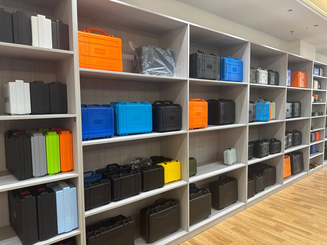
Reserve a fixed document pocket for a serial-numbered packing list, a sensitivity and calibration factor table updated after every recalibration, certificate copies for metrology audit, a case history card recording drops and wetting, a desiccant replacement log kept every three to six months, and a QR asset inventory list. The pocket is itself a management constraint: abnormalities are only recorded when the operator is obliged to answer whether anything abnormal was found at this opening, and an unrecorded abnormality becomes an unexplainable data spread in the next campaign.
Acceptance Criteria and Re-Verification Intervals
A protection case is not a one-off deliverable; it must retain verifiable performance over its life, so purchase documents should define re-measurable acceptance criteria and stated intervals.
| Item | Criterion | Test method |
|---|---|---|
| --- | --- | --- |
| Appearance and dimensions | No deformation, cavity tolerance within 2 mm | Visual and calliper |
| Sealing performance | IP65 or IP67, 0.3 m water for 30 minutes, no ingress | IEC 60529 or GB/T 4208 |
| Pressure-equalisation valve | Cracking at 15 to 50 mbar, no reverse leakage | Differential pressure and immersion |
| Liner fit | Lateral clearance at most 2 mm, top compression 1 to 3 mm | Feeler gauge and visual |
| Electrostatic performance | Liner surface resistance 1 x 10^4 to 1 x 10^9 ohm | High-resistance meter |
| Ground continuity | Terminal to furthest liner point at most 1 x 10^9 ohm | High-resistance meter |
| Drop test | Within target fragility per GB/T 4857.5 or ISTA 3A | Whole-case drop with recorder |
| Stacking load | 1.5 times stacking load for 24 hours, residual deformation at most 2 mm | Static load test |
| Salt spray | No substrate perforation after 480 hours neutral salt spray | GB/T 10125 |
| Label durability | Legible after 50 alcohol wipes | Wipe test |
Recommended intervals are quarterly for surface resistance, ground continuity, latch and hinge action and gasket appearance; half-yearly for seal performance, desiccant and indicator replacement and liner indentation checks; and annually for drop and stacking re-tests on a sampling basis, valve function and label durability. Run the three checks of seal, grounding and liner after every drop, immersion, over-temperature event or obvious impact, and record them in the history card.
Disposition rules matter as much as the tests. Replace rather than patch a gasket showing permanent deformation, cracking or increased hardness. Replace a liner region compressed by more than 20 percent of its original thickness as a module rather than re-lining the whole case. Downgrade a shell with cracks, distortion or failed latches to non-metrological duties such as cable storage. Replace outright any valve that has admitted water or shows abnormal cracking pressure. Where cases serve a coastal proving ground or salt-laden air, validate metal parts by Salt Spray Corrosion Test and focus inspections on hinges, latches and rivets, with fastener material and surface treatment written into the specification so a plated part never quietly replaces a stainless one.
Frequently Asked Questions FAQ
Q: What really separates an automotive test equipment case from a general instrument case?
A: The design intent differs. A general instrument case asks whether the contents fit and can be carried; an automotive test equipment case asks whether metrological state can be preserved and traced. Four differences follow. First, the liner supports transducer contours with area contact rather than point contact, protecting mounting faces and connector pins from the loads that cause sensitivity drift. Second, materials are specified for electrostatic behaviour, with surface resistance held between 1 x 10^4 and 1 x 10^9 ohm so that a dry-season discharge cannot puncture an input stage. Third, the case carries an identification system of serial numbers, sensitivity values and calibration dates plus a fixed document pocket, keeping certificates paired with the items they describe. Fourth, acceptance criteria are written as measurable physical quantities such as transmitted drop acceleration, ground-continuity resistance and ingress-protection grade, which means a technician can verify performance rather than assume it. Where the same transducer batch is used across several test cells, the serial-number log should record which cell each unit was shipped to, because a drift complaint is far easier to trace when the movement history is already on file. Q: How should a triaxial accelerometer be secured so that its sensitivity does not drift after transport?
A: Support the housing rather than the sensing structure, and limit movement in every direction. Carve a contour-matched recess in EVA at 40 to 60 kg/m³, give the base area support instead of point support, allow 1 to 2 mm of lateral location clearance, and apply light compression with 5 to 10 mm of soft IXPE or low-density PU above, keeping that compression between 1 and 3 mm. Store the cable in a separate groove, with an individual retention position for each transducer and a coil radius of at least ten times the cable diameter. After packing, tilt and shake the case in horizontal and vertical orientations; there should be no perceptible shifting inside the recesses. Let the case stand for two hours before powering up after transport, then confirm that the recalibrated sensitivity stays within plus or minus 2 percent of the previous certificate value. A larger deviation calls for recalibration and a root-cause investigation.
Q: What matters most when protecting DAQ front-ends and signal-conditioning modules?
A: Front-ends tolerate mechanical load less well than most transducers do. Non-operating shock limits usually fall between 30 g and 50 g half-sine at 6 to 11 ms, so the whole-case design should keep transmitted peak acceleration into the front-end chamber below 20 g. Structurally, place the front-end in a discrete chamber on the hinge side where shell stiffness is highest, add a 6 to 10 mm EVA pad beneath the chamber floor, and recess the liner by at least 8 mm on the front-panel side so that no lid or liner can strike an interface. A fan-cooled chassis cannot rely on airflow while the case is sealed for storage, so desiccant replaces ventilation in that condition. Before the system leaves the laboratory, short the inputs and record the noise floor and zero offset of every channel, then repeat the same reading before connecting anything at the next unpacking. This three-minute routine exposes transport-induced channel faults at the earliest possible stage, long before a full calibration slot is booked.
Q: How should EPE, EVA, IXPE and PU be divided between tasks?
A: A three-layer composite is the mature answer rather than choosing one material for everything. Use EPE at 25 to 35 kg/m³ as the outer support and large-area energy absorber, because its cushion curve is gentle, its efficiency is good in the 3.5 to 7 kPa static-stress band and it is closed-cell, so it does not wick moisture at a humid proving ground. Use EVA at 40 to 60 kg/m³ as the middle layer to carve contour recesses, giving a stable location boundary that keeps its dimensions without collapsing under the weight of the payload. Add 3 to 5 mm of IXPE or low-density PU as the inner contact layer between transducer and EVA to suppress fretting wear and surface marking in the 20 to 200 Hz band. Note that for transducers lighter than about 150 g, static stress on EVA is so low that it barely deforms; the outer EPE and the shell do the cushioning while EVA only locates and prevents abrasion.
Q: Why can a transducer not be unpacked and calibrated immediately after returning from a cold-weather site?
A: Because thermal equilibrium has not been reached. Moving from -20 °C into a 25 °C laboratory puts the case and transducer surfaces below the room dew point, so condensation forms quickly and moisture can migrate into connector pin gaps or bridge terminals, lowering insulation resistance and sometimes shorting a channel. Strain-gauge zero also depends on elastic-body temperature: a 350 ohm bridge drifts roughly 0.01 to 0.03 percent of full scale for every 10 °C change, so calibrating before equilibrium introduces error by definition. The correct sequence is to bring the case into the laboratory and let it stand, two to four hours for small transducers and up to six hours for heavy load cells and torque transducers, then record the start of the stabilisation period and the opening time on the travelling card before applying power and repeating the pre-transport channel self-check. Reconnect transducers only after the readings match that record. Marking each cable with its channel and its mating connector keeps a multi-channel rig from being reassembled with interchanged leads after a teardown. Q: Is a higher ingress-protection rating always better, and does every scenario need IP67?
A: No, and treating IP67 as universal wastes money and effort. IP67 means protection against temporary immersion, and the cost is a heavier shell, higher gasket compression, stiffer opening and a mandatory pressure-equalisation valve so that internal pressure cannot damage the seal. For cases that only move between rooms in one laboratory, IP54 is sufficient, lighter, easier to wash and cheaper to maintain. Grade by scenario instead: IP54 indoors, IP65 for cross-building campus moves, IP67 with a valve for cross-region road transport, and IP65 with desiccant and an indicator card for long-term storage. The real pitfall is storing an IP67 case sealed for months without desiccant, because sealing only stops new moisture from entering; it cannot remove the humidity already trapped inside at the moment of packing. Match the rating to the route the case actually travels, and inspect the gasket whenever a hose-down or a long motorway trip has taken place. The same check should be repeated after any return from a test cell that was reconfigured, because a connector that seated correctly in the old layout may bind in the new one. Q: How can a team decide that a liner needs replacing instead of being used a while longer?
A: Four quantifiable criteria work well. First, thickness recovery: measure the natural thickness at a recess and again after 24 hours under load; if residual deformation exceeds 20 percent of the original, replace that region. Second, surface condition: cracking, powdering, shedding or obvious compression dents indicate aged material that can no longer hold a stable shape. Third, location accuracy: lateral clearance above 2 mm, or perceptible movement when the case is shaken, means the location function has already failed and the transducer is relying on luck. Fourth, cleanliness: a liner that has absorbed oil, coolant or metal swarf cannot be cleaned reliably and will slowly contaminate every connector it touches. Where a case uses a modular liner, only the affected module is replaced rather than the whole case, which is a structural requirement worth writing into the purchase specification alongside the acceptance criteria. Where the case is shared between shifts, the inspection should be handed over in writing rather than assumed, since a small crack noticed at the end of one shift is easy to miss at the start of the next. Q: What extra protection and procedures should a field test team adopt?
A: Four measures help. First, split primary and secondary cases: keep the main case at the depot with the full equipment set, and carry a small cable bag with only the patch leads needed for the day, so mud and oil from vehicle testing never reach the primary liner. Second, secure loads in transit: fasten cases inside the vehicle, stack no more than three high and verify the bottom layer against a 1.5 safety factor. Third, carry spares: replacement gaskets, desiccant packs, a ground braid, antistatic gloves and common connector dust caps allow small faults to be fixed on site rather than ending a campaign. Fourth, scan in and out: register every issue and return by QR code and combine it with calibration-expiry alerts so that an overdue transducer cannot quietly stay in service. A field kit following these four habits returns with its calibration chain intact.
Conclusion and Related Reading
Bench instrumentation cases are calibration-chain hardware. JUNZHIJIA builds them to order, from liner geometry to tooling, OEM and ODM supply, verified by drop, stacking, seal and ESD testing. Manufactured by Kexin New Materials (Guangdong) Co., Ltd.
Related Reading