

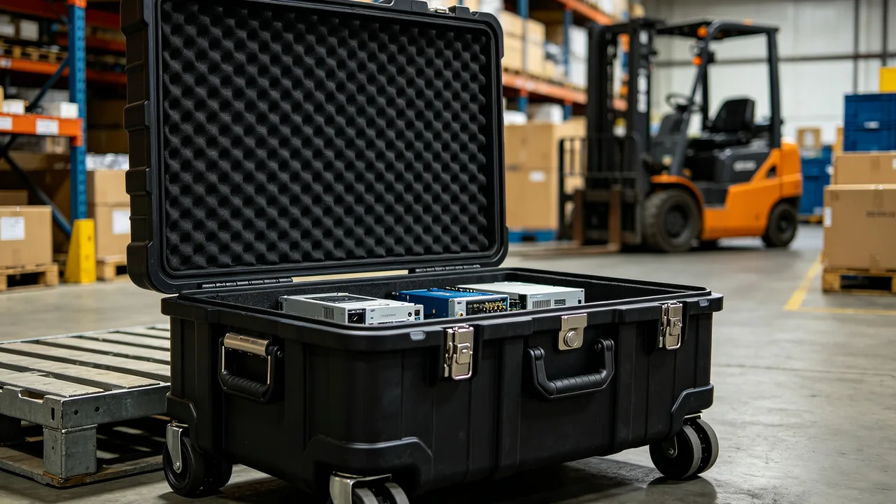
The load spectrum on a bulldozer is the harshest in the earthmoving family. Dozing applies continuous push force, while ripping applies intermittent tearing impact. That reality forces both of its major attachments, the blade and the ripper, to be built large and thick, and large thick structures that deform in transit cannot realistically be straightened in the field. Three criteria summarise the approach: a blade is a large-area welded shell and must be supported at multiple evenly distributed points to eliminate self-weight bending, with cutting edges and corner bits wrapped in segments rather than loaded as one continuous strip; the push arms and braces are the primary load path for dozing reaction and must either ship in their original assembled relationship or be fitted with rigid restraints, never left to weld seams alone; and ripper shanks and tips are heavy cast or forged parts requiring individual pockets with stacking prohibited and a safe clearance maintained between tip and case wall. One further characteristic of bulldozer components is easily underestimated: because they work directly in soil and gravel, they carry abrasive residue on their surfaces, and if that residue is not cleaned before packing it turns the case interior into a grinding environment.
When bulldozers are exported or receive major component replacement, the blade assembly, ripper assembly, undercarriage and hydraulic parts typically travel separately. Compared with excavator parts, bulldozer disassembled components are wider and flatter. Blade width commonly reaches 3 to 5 m, making them oversized flat items that no conventional case can contain, so cradles and split packing become necessary. Ripper shanks are long cantilever heavy parts with a high centre of gravity and a small footprint, making them the most tip-prone items at the packing station. The sections below follow the sequence blade, edge, push arm, ripper shank, ripper cylinder, undercarriage, liner, impact control, corrosion control, testing and documentation, giving verifiable methods and criteria at each step.
Table of Contents
- Protection Objectives and Criteria for Bulldozer Parts Cases
- Blade Shell Welded Structure and Deformation Risk
- Segmented Protection for Cutting Edges and Corner Bits
- Rigid Restraint for Push Arms and Braces
- Ripper Shank and Tip Casting Protection
- Load Isolation for Ripper Cylinders and Linkages
- Zoned Loading for Track Frames and Undercarriage Parts
- Liner Material Selection Under Impact Duty
- Impact Control: Isolation, Cushioning and Limiting
- Corrosion Control Against Salt Fog and Soil Residue
- Test Plan and Acceptance Criteria
- Packing Unit List and Delivery Documents
- Frequently Asked Questions
- Conclusion and Related Reading
Protection Objectives and Criteria for Bulldozer Parts Cases
Protection objectives must be written in decidable form, otherwise acceptance degenerates into opinion. Three criteria work well for bulldozer components.
The first is a geometric criterion. Every feature whose function depends on flatness or straightness must retain its factory value after transit. Specifically this means the push arm mounting face on the blade back, the straightness of the edge seat, and the straightness of the ripper shank.
The second is a contact criterion. In the transport condition, no two items may touch metal to metal, and nothing may touch the case wall through a material harder than itself.
The third is a displacement criterion. After tilting the packed case 30 degrees and holding for ten minutes, then returning it upright, relative displacement must not exceed 2 mm and no new impression may appear in the liner.
The ordering matters. The geometric criterion covers irreversible loss and ranks first, the contact criterion covers preventable damage and ranks second, and the displacement criterion is the means of achieving the first two. In practice, many packing arrangements satisfy the displacement criterion by clamping tightly while violating the geometric criterion through poorly placed supports. Checking must therefore follow the order rather than stopping at whether the case feels solid at dispatch.
Applying these criteria requires inputs: a three-dimensional model or measured outline, individual mass and centre of gravity, marked locations of functional machined faces, and a description of the worst conditions on the transport route. Without any one of the first three, liner design becomes guesswork and risk rises sharply. Dimensional practice for pocket layout in custom liners is described in custom foam insert pocket design.
The step most often skipped at the packing station is cleaning. Bulldozer components carry soil, grit and old grease. Unless these are removed, the parts dried and temporary rust prevention applied, the three will act together under vibration and turn the case interior into an abrasive environment.
Blade Shell Welded Structure and Deformation Risk
A bulldozer blade is a large-curvature thin shell welded from a curved face plate, upper and lower beams, ribs and side plates. Structurally efficient, it is poorly suited to transport for three reasons: large area, uneven stiffness distribution and almost no supportable flat surfaces.
Large area means a large wind profile that swings during lifting, and it means any single-point support leaves a visible impression in the face plate. Uneven stiffness means high rigidity where ribs are dense and low rigidity between ribs, so supports must land on rib or beam locations. A support placed between two ribs presses directly on the face plate. The absence of flat support surfaces means the blade cannot be carried on a flat bed and instead requires curved saddles matching blade curvature.
| Blade type | Typical width | Empty mass (kg) | Structural feature | Recommended packing |
|---|---|---|---|---|
| --- | --- | --- | --- | --- |
| Straight blade | 3.0 - 4.0 m | 1800 - 3200 | Single curvature, no side plates | Curved saddle cradle, four or more supports, lateral limiters |
| Angle blade | 3.5 - 4.5 m | 2400 - 4200 | Side plates and tilting mechanism | Cradle, locked tilt mechanism, plate corner guards |
| Universal blade | 4.0 - 5.0 m | 2800 - 5000 | Deep curvature with side plates | Cradle, distributed supports, top hold-down beam |
| Semi-universal blade | 3.5 - 4.5 m | 2200 - 3800 | Moderate curvature | Curved saddles, four-point support |
| Coal blade | 4.0 - 6.0 m | 3000 - 5500 | Raised face, large capacity | Cradle, separate support for raised section, anti-roll clamp |
The tilting mechanism on an angle blade needs separate treatment. It comprises a rotation gear ring or bearing plus a locking device. If the rotation degree of freedom remains unlocked in transit, the blade swings slightly about its rotation centre under vibration, and that swing transfers into the pin bores connecting push arms and braces, causing bore wear and increased clearance. The disciplined method is to lock the tilt mechanism at mid-position and treat that locking device exactly like a transmission lock: shipped with the part and tagged for removal.
On universal and coal blades with tall side plates, plate edges are the features most easily struck by rigging. Fitting corner guard blocks in engineering plastic or laminated timber at the upper and lower plate corners keeps slings from cutting directly into thin plate edges.
Segmented Protection for Cutting Edges and Corner Bits
Cutting edges and corner bits are the only parts of the blade that directly engage the ground, and they are also the hardest to remedy if damaged in transit. Bulldozer cutting edges normally consist of a centre edge plus two end bits, each bolted to the edge seat with countersunk bolts. Segmented design exists to make replacement easy, but it also means each segment is a separate item that can come loose independently in transit.
Three requirements follow. First, edges must not face downward. Cutting edge angles typically run 25 to 35 degrees with an edge thickness of only a few millimetres, so anything hard pressed against the edge will roll or chip it. Second, protection must be segmented rather than continuous. Each segment receives its own soft edge strip, with gaps left between strips, so that impact on one segment is not transmitted through a continuous strip into its neighbours. Third, corner bits should have individual pockets. Corner bits are angled and asymmetric, so generic liner material allows movement, whereas a shape-matched pocket holds them properly.
The edge seat is welded to the lower blade edge and its flatness determines how well the cutting edges bed down. If the seat picks up a local depression in transit, gaps appear between edge and seat after installation, and debris enters those gaps and widens them further. The edge seat region should therefore be non-load-bearing inside the case, facing sideways or upward.
Countersunk bolts and nuts are small loose items. A bulldozer blade set may use dozens of bolts in a few sizes. Packing them by segment, each segment's bolts in a separate bag with the segment number marked, prevents length mixing on site. Countersunk bolt head height is matched to the countersink depth, so mixing them creates a raised edge that protrudes above the blade surface.
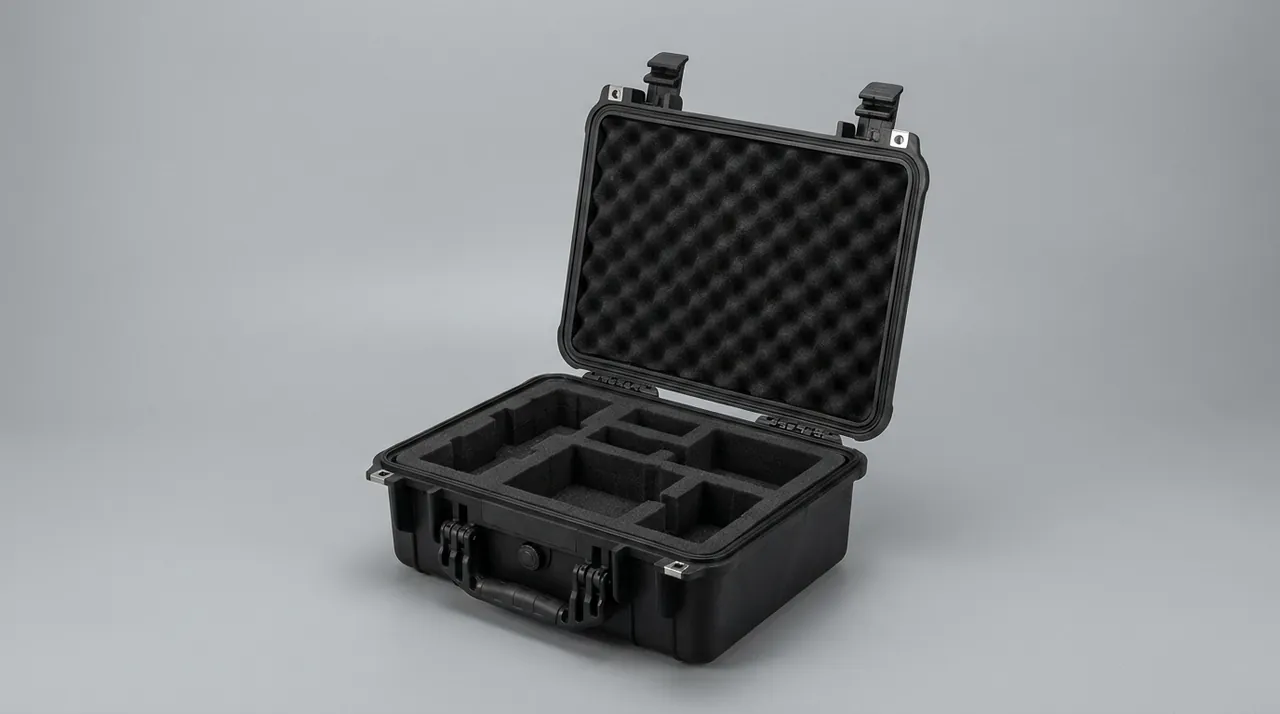
Edge protection for heavy castings and thick plate follows the same logic, and comparable cushioning and support detail is described in cushion liner and support structure design, including contact area and hardness gradient guidance.
Rigid Restraint for Push Arms and Braces
Push arms and braces are the structural bridge between blade and machine, carrying the full dozing reaction, which is why they have large sections, numerous welds and precision pin bores. The transport problem is not insufficient strength but a restraint method that fatigues the welds.
A push arm is typically a box-section weldment with a large pin bore at each end. If supported or slung at a single point in transit, it resonates about that point, concentrating vibration energy in the welds and plate transition zones near the pin bores. Those zones are usually ground and inspected, but repeated vibration can still initiate cracks at the weld toe. The correct method is to preserve the arm's assembled relationship with the blade or the frame, using the same rigid connection as on the machine, then add a resilient mid-span support to absorb vibration.
Braces demand stricter restraint because a brace is a two-force member designed for axial load only, with no allowance for bending. Left free at an angle in transit, its self-weight creates bending in its own section, and prolonged static loading or transport vibration can produce plastic curvature. Braces should stay at or close to their design installation angle, and where the angle must change, a temporary support should route bending moment into the case.
Pin bore protection applies to both push arms and braces. Bore cylindricity and surface roughness determine the clearance after pin installation, so each bore needs a matched process plug, preferably in engineering plastic. Metal plugs wear better but scratch the bore wall the moment grit enters. Bores must also be confirmed dry and coated with temporary rust preventive grease before packing, so that marine humidity does not rust the bore wall.
Where push arm and blade ship already connected, the combined centre of gravity shifts markedly toward the blade, so lifting points must bias to the heavy side and a trial lift should confirm the tilt direction before the main lift. Lifting point offset logic follows the same principle applied to axle housings, and the treatment of heavy part lifting points and support faces in winch component transport protection is directly transferable.
Ripper Shank and Tip Casting Protection
The ripper breaks hard soil, rock strata and pavement. Structurally it consists of several shanks mounted on a beam, each carrying a tip at its lower end, with hydraulic cylinders adjusting penetration angle and depth. Ripper components are characterised by heavy individual mass, high length-to-thickness ratio, and widely varying surface hardness.
Shanks are usually one-piece castings, forgings or thick plate cut parts, weighing 200 to 600 kg each and measuring 1.0 to 1.6 m long. Their centre of gravity sits near mid-length and the footprint is small, making tipping and mutual collision the main transit risks. Packing must deliver individual pockets: one cavity per shank, cavity depth not less than half the shank section height, high-density load-bearing material beneath, and liner material wrapping both flanks without clearance.
Tips are the hardest components on the ripper, usually wear-resistant alloy castings or hardfaced structures reaching HRC 50 or above. High hardness comes with low toughness, so tips are most vulnerable to point impact. A sharp hard object striking the side of a tip can chip it. Tips should face the same direction and maintain a safe distance from the case wall, with a soft divider inserted where distance is insufficient. Two tips must never face each other inside one cavity.
The beam and adapter block is a welded structure, and its pin bore or slot is the locating datum for the shank. Once that datum face is burred, the shank rattles after insertion, and working impact load passes into the pin rather than being shared by the mating faces, which shortens pin life noticeably. Adapter regions should therefore be protected by filling rather than by direct clamping.
Pocket design and support principles for heavy cast or forged parts closely match those for high-hardness forging dies, and the treatment of point impact protection and individual pocketing in forging and casting heavy part packing applies directly.
Load Isolation for Ripper Cylinders and Linkages
The ripper cylinder adjusts shank attitude. Its stroke is moderate but its load is very high, with bore diameters commonly exceeding 100 mm. Transport protection principles match those for blade cylinders, but because a ripper cylinder normally forms part of a four-bar linkage, the force relationships in the transport condition are more complex and load isolation deserves specific attention.
Load isolation means that in the transport condition the cylinder must not act as a stressed member of the linkage. If the cylinder remains connected and rigidly restrained in a machine-like configuration, case vibration passes through the linkage as axial alternating load. A cylinder can carry working pressure, but the frequency and amplitude of transport load fall outside its design envelope, and the outcome can be repeated friction of the seal lip against the guide sleeve without oil lubrication, producing early weeping.
Two methods are recommended. The first is separated shipment: cylinder and linkage are split, each packed independently, the rod retracted inside a full-length sleeve, and linkage bores fitted with process plugs. This is the safest arrangement, at the cost of on-site reassembly. The second is assembled shipment: the original assembly relationship is preserved, but a rigid stop must be fitted into the four-bar linkage to lock it at the design position, and circuit pressure released so the cylinder carries zero load in transit. The chosen method must be stated in the packing documentation so that site staff can act correctly.
Port plugging and cleanliness requirements match other hydraulic components: threaded plug plus dust cap, a plug list inside the case, and a tag stating removal before installation. Cleanliness should be managed on the ISO 4406 scale, with preservation targets for ripper cylinders and main control valves of at least 19/17/14 and 18/16/13 respectively.
Rod sleeves for ripper cylinders should use nitrile rubber or expanded polyethylene, never bubble film. The reason matches blade cylinders: torn bubble plastic edges rub repeatedly against the coating under vibration and generate scratches.
Zoned Loading for Track Frames and Undercarriage Parts
Track frames, undercarriage frames, track rollers, carrier rollers, sprockets and idlers make up the undercarriage. These components are numerous, individually heavy, irregular in shape, and mostly carry fit precision requirements, whether roller-to-shaft fits or frame mounting bores.
Zoned loading is the basic method. Divide by function and precision: high-precision fit parts such as sprockets and idlers form their own zone with individual pockets and bore protection; medium-precision parts such as track and carrier rollers group into a zone with uniform liner material but dividers between every item; structural parts such as undercarriage and track frames form a zone of their own with support faces as the primary measure. Zoning keeps protection requirements consistent within a group and reduces cross-damage from mixed loading.
Track rollers and carrier rollers present risks mainly at the shaft end and seal. The cast or forged roller body tolerates impact well, but the shaft end seal is small in diameter with a thin lip that deforms on any hard contact. Stand rollers upright so the rim carries load with the shaft end free, and fit a protective cap. If laid flat, the shaft end must face upward inside the case and never downward.
Sprockets and idlers present tooth flanks and rims as mating surfaces, and many are split designs. They should ship assembled with tooth guards fitted. Their bores and bearing seats need process plugs and protective caps, with removal sequence noted in the packing documents.
Undercarriage and track frames are long skeletal parts that can exceed 3 m. They need at least three supports along their length, placed on primary beams or reinforcement ribs rather than on flat panels. Where stacking is unavoidable, a rigid divider as wide as the case must carry the upper load into the case wall rather than passing it through the lower part.
Track shoes and pins are high-wear items usually shipped loose in quantity. Impact does not worry them, but soil does. Soil and grit clinging to track shoes fall away during long transit and spread into other zones, so cleaning and drying before packing is mandatory. Zoned loading and support practice for heavy undercarriage components is described further in mining and earthmoving heavy component packing.
Liner Material Selection Under Impact Duty
Impact contributes a larger share of transport duty for bulldozer components than for excavators or loaders, because items such as undercarriage parts and ripper shanks concentrate significant mass into a small volume. When restraint fails, impact energy density is high. Liner material should therefore lean toward high energy absorption and low rebound rather than simply soft.
High absorption means the material converts energy through plastic deformation or cell collapse under compression. Low rebound means it does not return that energy to the part at high speed on unloading. By this standard, polyurethane foam and EPP score well, while EPE and low-density EVA suit surface cushioning rather than primary support.
A composite structure works best at primary support locations: laminated timber or high-density polyurethane at the base to route weight into the case wall, medium-density polyurethane in the middle for shape restraint, and XPE or flocked material at the surface for contact protection. Under impact, energy passes through surface layer, restraint layer and base layer in sequence, attenuating at each step.
| Liner location | Primary function | Recommended material | Key metric |
|---|---|---|---|
| --- | --- | --- | --- |
| Load-bearing base | Route weight into case wall | Laminated timber or high-density PU | Compressive strength, creep resistance |
| Shape restraint | Limit contents displacement | Medium-density PU or EVA | Compression set, resilience |
| Contact cushion | Protect surfaces, absorb micro-vibration | XPE, flocking or EPE | Thickness consistency, low leachate |
| Isolation divider | Block item-to-item contact | Rigid engineering plastic or laminate | Stiffness, deburred edges |
| Hold-down element | Eliminate assembly clearance | Resilient strip or foam bar | 25 to 35 percent compression |
Note the trade-off between creep resistance and energy absorption. Choosing very high density for creep resistance reduces absorption; choosing low density for absorption undermines long-term restraint. The sensible answer is to divide the work by location: where sustained static load dominates, prioritise creep resistance; where impact is credible, prioritise absorption.
Material compatibility with metal components matters particularly on bulldozers, because surfaces often carry soil and moisture. A liner material with high water absorption sustains a humid environment inside the case. Closed-cell materials are preferable, with a moisture barrier film at the base layer.
Impact Control: Isolation, Cushioning and Limiting
Impact control must handle three distinct contact scenarios with three corresponding measures. Omitting any one leaves that scenario unprotected.
The first layer is isolation, handling item-to-item contact. It uses rigid dividers that physically block contact, and each divider must independently carry the loads generated by the adjacent items' masses rather than merely sitting on foam as a token separation. The key parameters are divider thickness and edge treatment, and edges must be radiused or bound so the divider does not become a cutting source itself.
The second layer is cushioning, handling item-to-case contact. Compressible material sits between component and case wall at 25 to 35 percent compression. Below that, cushioning travel is insufficient and impact transmits into the wall. Above it, the material bottoms out and loses resilience, and associated parts such as gaskets are over-compressed.
The third layer is limiting, handling the component's own displacement. Rigid stops block movement in the primary impact direction while resilient hold-down elements eliminate assembly clearance. Rigid stops absorb energy, resilient elements maintain contact, and both must be present. Resilient elements alone allow cumulative displacement beyond their travel under vibration; rigid stops alone leave the component hammering within clearance between itself and the stops.
Case hardware selection is part of the impact control system. Bulldozer parts cases usually need handles or lifting points on all four sides, and latch count and preload directly affect sealing and clamping. Hinge and latch capacity should match use frequency, and returnable cases opened frequently are better served by latches with metal reinforcement pads. Structural detail on latch spacing and gasket compression is covered in toolbox hinge, latch and seal structure.
Corrosion Control Against Salt Fog and Soil Residue
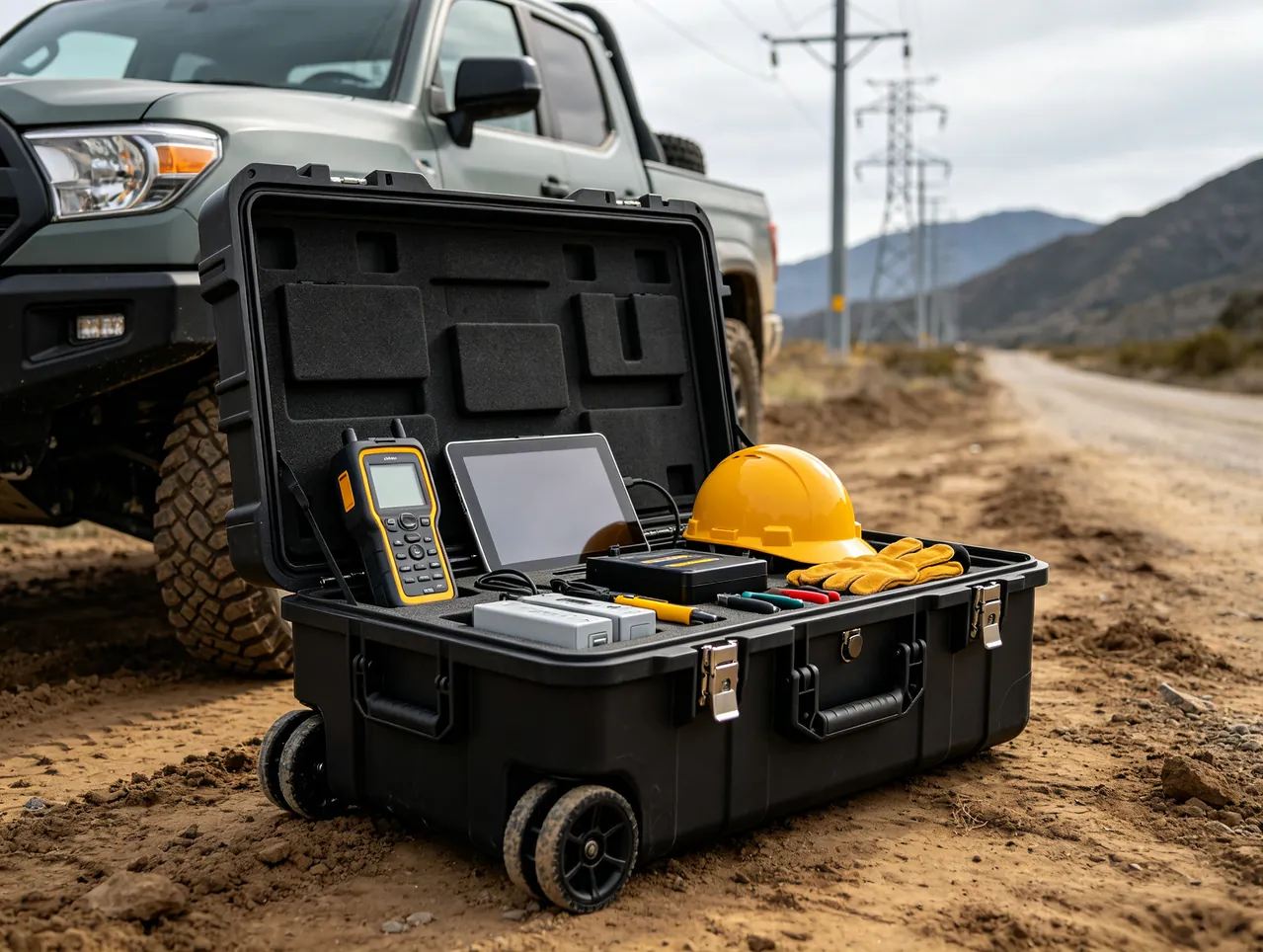
The working environment of a bulldozer determines the surface condition of its components: a mixture of soil, grit, moisture and old grease. That mixture is corrosive in its own right, and clayey or saline soils in particular form local corrosion cells where they remain attached. The corrosion control system for bulldozer parts cases must therefore include pre-packing cleaning as a mandatory step, which is the key difference from other construction machinery parts.
Cleaning requirements should be quantified: no visible mud clods or loose grit, no free water, and no grease layer thick enough to prevent rust preventive coating adhesion. Rust prevention should follow within a defined interval after cleaning to avoid recontamination. On complex castings, interior recesses and blind holes are the most likely to trap water and grit and deserve specific attention with drying by compressed air.
Rust prevention differs by feature type. Machined surfaces such as pin bores, mating faces and adapter datums take rust preventive grease or soft-film oil at 20 to 40 micrometres. Non-machined structural surfaces can take a fast-drying preventive agent that is easy to remove on site. Fasteners and small parts go into vapour phase inhibiting film. VCI film service life under sealed conditions is typically 12 to 24 months, covering normal sea freight and warehousing.
Case level protection covers sealing and drying. Sealing grade follows transport mode, with IP67 on the primary gasket advisable for ocean freight, verified to IEC 60529 or GB/T 4208, plus desiccant and a humidity indicator card inside. Gasket weathering resistance, compression set and temperature range must match the transport environment, and material boundaries between silicone, EPDM and nitrile are described in seal material selection and compatibility.
For corrosion testing, the governing reference is the salt spray method inside GB/T 10125, the artificial atmosphere corrosion test series. A neutral salt fog regime is normally applied, with sodium chloride concentration held near 50 grams per litre and chamber temperature controlled around 35 degrees Celsius. For bulldozer parts whose surfaces have contacted soil, specimens should be prepared using the actual cleaning process before testing, otherwise the result will not represent the real condition.
One detail often overlooked: desiccant must sit where it cannot contact the contents directly, such as a mesh pocket in the case lid or a corner bracket. A loose desiccant sachet that ruptures releases granules onto hydraulic surfaces and becomes a contamination source.
Test Plan and Acceptance Criteria
A bulldozer parts case test plan is best organised along three lines, static, dynamic and environmental, each with explicit criteria rather than a general requirement to pass.
The static line covers stacking tests and bearing creep observation. Stacking load follows actual stack layers plus one layer of margin, held for at least 24 hours. Creep observation targets the liner, checking whether bearing point depressions exceed 10 percent of original thickness and whether they recover after resting.
The dynamic line covers random vibration, shock and drop. Domestic work references the GB/T 4857 family, which sets out basic tests applied to transport packages. Overseas routes may instead follow an ISTA procedure or an ASTM D4169 distribution cycle, matched to the journey actually taken. For packaging units containing heavy castings, post-vibration inspection should focus on contents displacement, liner impressions, fastener loosening and divider deformation. Acceptance criteria are displacement under 2 mm with no through-thickness impressions. Method for selecting the distribution cycle and assurance level in ASTM D4169 is set out in ASTM D4169 distribution cycle simulation.
The environmental line covers salt spray, damp heat and thermal shock. Conditions and duration follow the destination port environment, with criteria of no red rust on metal parts, no blistering or flaking of coatings, and no hardening or cracking of seals. Where MIL-STD-810H methods are cited, the citation should state that the standard serves only as the source of environmental test methods and conditions for verifying product behaviour in those environments, and that it is not a military certification and confers no military qualification of any kind.
Test sequencing should run static first, then dynamic, then environmental. The reason is that environmental checks usually require opening the seal to inspect inside, so placing them last preserves intact specimens for the first two lines. Test records should include specimen number, conditions, observations and photographs as part of the delivery documentation.
Packing Unit List and Delivery Documents
Delivery documentation for a bulldozer parts case is more than a packing list. It should include a packing unit list that binds case, liner and contents into one traceable technical file.
The packing unit list should carry these fields: case number, liner drawing number, liner revision, component name and part number, quantity, individual mass, centre of gravity, locking device list, plug list, test report number, packing date, packer and verifier. The purpose of these fields is to let any later claim be traced quickly to a design, material or workmanship cause.
Where a packing unit contains hydraulic components, a plug list and a removal tag list should be attached, with photographs of the physical tags filed. Experience shows that missed removal of locking devices and plugs is a leading cause of on-site start-up faults, and dual records, meaning physical tags plus written documentation, reduce that probability substantially.
For custom projects, the cost structure and amortisation logic of tooling and sampling stages should be discussed in advance to avoid cost disputes at volume stage. Cost structure and mould life assessment methods are described in custom case mould cost analysis.
Documentation language and marking should match destination country requirements. Export items are best served by bilingual labels covering part number, name, mass, lifting points, stacking limits and removal before installation. Label material must resist salt fog and ultraviolet exposure so that printing remains legible after an ocean voyage.
Frequently Asked Questions
Q: For a bulldozer blade wider than 4 metres, which packing method is most practical?
A: At that width the blade exceeds the sensible range of a conventional case, and a curved saddle cradle becomes the primary solution. The essential point is that saddle curvature must match the blade back curvature with a contact angle of at least 120 degrees, and at least four support points must be placed on rib or beam locations. Two of them should sit at the ends near the side plates to suppress end droop. Placing supports between ribs on the flat panel is a common error, because that is the lowest stiffness region and sustained loading produces irreversible panel depressions. A removable hold-down beam above the blade presses it onto the saddles and limits vertical movement. Beam tightening torque belongs in the work instruction and should be confirmed by the verifier. For stacking requirements, a single layer is normally the safest choice; where two layers are unavoidable, the upper layer should hold light items with a rigid divider as wide as the cradle between layers. All support and clamping points must be marked on the packing drawing with positions and sequence so that the site does not rely on judgement.
Q: Segmented protection for bulldozer cutting edges sounds like extra work. Is one continuous strip simpler?
A: A continuous strip is simpler but creates a defined failure path. Bulldozer cutting edges consist of a centre edge and two end bits with designed clearances between segments for thermal expansion and assembly. A single continuous strip ties the segments together, so impact on one segment transmits through the strip into neighbouring segments and the edge seat, amplifying a local impact into multi-segment loading. Segmentation exists precisely to break that transmission path and let each segment absorb and cushion independently. In practice, each segment receives its own edge wrap with gaps between wraps corresponding to the segment clearances, and those gaps are left unfilled. Segmentation has a second advantage: if one wrap is found damaged, only that segment needs replacement rather than the whole strip. Polyurethane at Shore A75 to A90 works well. Material harder than that damages the edge, and softer material lacks cushioning travel. Corner bits are asymmetric and need shape-matched individual pockets.
Q: Why must ripper shanks be individually pocketed? Can they not simply be bundled together?
A: Bundling fails because of the shank's mass characteristics. A single shank can weigh 200 to 600 kg with a length of 1.0 to 1.6 m, a centre of gravity near mid-length and a small footprint. It is a classic high centre of gravity long cantilever. When several are bundled, the contact points between them are undefined, and the binding force relaxes gradually under transport vibration. Once relaxed, the shanks move relative to each other and collide. More critically, a shank surface has regions of clearly different hardness, between hardened zone and base material. The softer regions are repeatedly struck by the harder regions of adjacent parts, producing local plastic deformation and crack initiation sites. Individual pocketing means one cavity per shank, cavity depth not less than half the section height, high-density support beneath and liner material wrapping both flanks without clearance. Where case dimensions force same-cavity placement, rigid dividers must separate each shank individually, and shanks must never share a divider. Tips and shanks are two separate items and must be fixed separately, never using the tip as a support point.
Q: For ripper cylinders, is separated shipment or assembled shipment better?
A: Both are viable, and the deciding question is which one removes the cylinder from the load path. Separated shipment is safest: cylinder and linkage are split so the cylinder carries only its own weight, the rod is retracted inside a full-length sleeve, linkage bores take process plugs, and reassembly happens on site. The cost is that the site needs assembly capability and torque tooling. Assembled shipment suits sites with limited facilities, but requires a rigid stop fitted into the four-bar linkage to lock it at the design position and released circuit pressure so the cylinder carries zero load in transit. If neither the stop nor the pressure release is done, case vibration passes through the linkage as axial alternating load, and the seal lip between rod and guide sleeve rubs without oil lubrication, producing early weeping after installation. Either way, ports must be double-plugged with a threaded plug and dust cap, locking devices and plugs ship with the part and carry removal tags, and the packing documentation must state the transport condition and the on-site handling steps.
Q: Why is zoned loading so important for undercarriage parts, and what exactly goes wrong with mixed loading?
A: Zoned loading addresses three specific problems. The first is precision mismatch. Sprocket and idler shaft end seals have thin lips and small diameters, and deform the moment a heavier, irregularly shaped component such as a track roller presses against them, while those heavier components are typically restrained only by liner material and are permitted small movement. The second is contamination spread. Track shoes and rollers commonly carry soil and grit that falls away and settles on high-precision mating surfaces, acting as an abrasive. The third is unloading sequence. Zoning allows unloading from highest precision to lowest, avoiding the need to disturb a whole zone of structural parts just to reach a precision item at the bottom. The method is to divide by precision into three zones: high-precision fit parts individually pocketed with bore protection; medium-precision parts grouped with mandatory dividers between every item; and structural parts supported on bearing faces. Zones must be physically separated by rigid dividers rather than foam alone. The zoning plan should appear on the packing drawing and be identifiable on site by colour-coded liner material or labels.
Q: Is a higher liner density always better, and which material is safest for bulldozer components?
A: Higher density is not automatically better; it depends on location. Higher density brings better compressive strength and creep resistance, but energy absorption usually drops and cushioning travel shortens. Among bulldozer components, locations under sustained static load, such as cradle saddles and case floor support layers, should prioritise creep resistance with high-density polyurethane or laminated timber. Locations exposed to credible impact, such as shank cavity walls and corner bit pockets, should prioritise energy absorption with medium-density polyurethane or EPP. Locations touching component surfaces, particularly near machined faces, should prioritise surface protection with XPE or flocking. In practice a composite structure works best: load-bearing base, restraining middle and cushioning surface, starting from a 3:4:3 thickness ratio and adjusting as needed. The trade-off between creep resistance and absorption cannot be solved with a single material, only by dividing work across layers. Before committing, run a trial fit and rest it for 24 hours, then check whether bearing point depressions exceed 10 percent of original thickness without recovering. That is the most direct criterion available.
Q: Bulldozer components have contacted soil. How thoroughly must they be cleaned before packing?
A: Cleanliness should be quantified against three requirements: no visible mud clods or loose grit, no free water, and no grease layer thick enough to prevent rust preventive coating adhesion. Each corresponds to a failure mechanism. Mud and grit fall away under transport vibration, spread through the case and become abrasive particles once they reach hydraulic surfaces or mating faces. Free water creates a sustained high-humidity environment inside a closed case, causing vapour phase film and rust preventive oil to fail prematurely. Excessive grease prevents the coating from adhering, and once the coating flakes off, bare metal becomes a corrosion initiation site. Operationally, remove bulk soil first, then brush or low-pressure water wash, then dry with compressed air, focusing on blind holes, recesses and threaded holes that trap water and grit. Rust prevention and packing should follow within a defined interval, without open storage in between. For complex castings, an internal inspection with a light before packing is worth doing. Finally, if the case is returnable, cleaning should happen outside the packing area so that soil is not carried into the packing zone and onto other components.
Q: Is salt spray testing of the case itself necessary when the components already have rust prevention?
A: It is necessary, because the two protect different things. Component rust prevention protects the component body, while case salt spray testing evaluates case hardware such as hinges, latches, skeletons and rivets, along with the corrosion resistance of the sealing system. Once case hardware corrodes, the effect is on opening function and sealing preload: a seized hinge prevents the lid from opening properly, and a corroded latch loses preload and causes sealing failure. By the time such problems are noticed on opening, water ingress or damp damage has usually already occurred. Test duration should track the destination environment. For inland transport a 48 hour exposure showing no red rust is a workable threshold. Ocean freight justifies 240 hours, while long coastal storage can be pushed to 480 hours. The test itself references GB/T 10125, applying a neutral fog with roughly 50 grams per litre of sodium chloride at a chamber temperature near 35 degrees Celsius. A caution belongs here: exposure hours do not translate arithmetically into years of outdoor service, because real exposure also brings wet and dry cycling, sunlight and deposited pollutants. Its proper use is comparative evaluation between design options, or as an agreed contractual acceptance baseline.
Conclusion and Related Reading
A bulldozer parts case has to handle the hardest class of components in earthmoving. Large-curvature blade shells need support at rib locations to eliminate self-weight bending. Cutting edges need segmented wrapping to break the impact transmission path. Push arms and braces must retain their assembled relationship or receive rigid restraint. Ripper shanks need one pocket each with tips kept clear of the case wall. Ripper cylinders must be isolated from the load path. Undercarriage parts need zoned loading by precision class. Liners must divide creep resistance and energy absorption by location. And cleaning, rust prevention, salt spray and vibration testing turn each assumption into a verifiable criterion. JUNZHIJIA, manufactured by Kexin New Materials (Guangdong) Co., Ltd., provides integrated cradle and case solutions for bulldozer, loader and other earthmoving equipment parts, covering custom liner design, case moulding, and global supply for wholesale, agency, OEM and ODM customers, with material certificates and test documents available under contract. For selection support, provide a three-dimensional or measured outline, individual mass and centre of gravity, destination port and transport mode, and support point layout, liner drawings and test plans can be issued directly.
Related Reading