

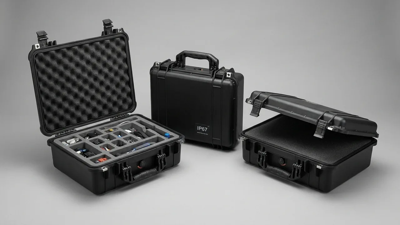
Three classes of hardware in a surveillance system fail during transport for entirely different reasons. Optical lenses tolerate neither pressure nor abrasion because their anti-reflective coatings are only micrometres thick. Mechanical hard drives hold their read/write heads a few nanometres above the platters and receive no active protection at all while the power is off. Outdoor cameras depend on an IP67 sealing path that cannot be restored once a gasket has been crushed out of shape. Packing bullet cameras, domes, NVRs, lenses, brackets, power supplies and cable reels into one box puts three incompatible failure modes into a single vibration source. Conclusion: transport protection for surveillance hardware must treat the lens, the hard drive and the sealing surface as three separate failure paths, each with its own contact geometry, damping layer and retention method, rather than filling the case with one generic sheet of foam. This article provides measurable cavity and cutout dimensions, desiccant quantities, sealing-face handling rules and an acceptance test list that can be copied directly into a purchasing specification.
The most common rework scenario is also the hardest to trace. A case arrives with no visible external damage, the box is opened during receiving inspection and nothing looks wrong, and only after the equipment is mounted on a pole does anyone notice fine scratches inside a dome bubble, a disk error on an NVR, or water ingress at an outdoor camera gland after the first rain. None of those faults surfaces during the five minutes of unpacking, yet all of them erupt at the project acceptance milestone. Worse, responsibility is difficult to assign, because the carrier, warehouse and installation teams each point elsewhere and the integrator absorbs the replacement cost. Designing protection into the packaging specification is the only reliable way to reduce this hidden loss.
Table of Contents
- 1. Transport Risk Profile: Where Each Device Fails
- 2. The No-Pressure, No-Scratch Rule for Optical Lenses
- 3. Dome and Bullet Geometries in One Case
- 4. NVRs and Storage Servers: Hard Drive Shock Comes First
- 5. Power Supplies, PoE Switches and Cable Management
- 6. Lenses, Brackets and Small Parts Without Scratches
- 7. Moisture and Static: The Real Failure Drivers Outdoors
- 8. Protecting the IP67 Sealing Path in Transit
- 9. Case Architecture: Hinges, Latches and Gaskets
- 10. Custom Foam Inserts: EVA, PE, PU and Dissipative Options
- 11. Transport Testing and Acceptance
- 12. How JUNZHIJIA Delivers These Cases
- 13. Typical Configurations and Case Size Recommendations
- Frequently Asked Questions
- Conclusion and Further Reading
1. Transport Risk Profile: Where Each Device Fails
A mid-sized video surveillance project generates a bill of materials with four groups of hardware: field devices, transmission equipment, recording equipment and power accessories. Their masses, envelopes and sensitive axes differ enormously, yet they are routinely packed on the assumption that one box will do.
Field devices include bullet cameras, dome cameras, high-speed PTZ domes and multi-sensor panoramic units. A bullet camera commonly measures 200 to 400 mm long with a barrel diameter of 60 to 110 mm, and once a sunshield and mounting bracket are fitted, its centre of gravity sits well off the optical axis. A high-speed PTZ dome typically has a 220 to 230 mm sphere and weighs 3 to 7 kg, usually in a die-cast aluminium housing with an acrylic or polycarbonate bubble. Dome cameras are small but arrive in quantity, often a dozen or more to a case.
Transmission equipment covers PoE switches, media converters, optical transceivers, patch cords and copper cable. None of it is delicate on its own, but a carelessly coiled cable behaves like a rigid spring and presses repeatedly against whatever sits beside it.
Recording equipment is where the highest value and the greatest shock sensitivity meet. A 3.5-inch enterprise hard drive is rated for roughly 30 to 70 G (2 ms half-sine) while operating and 250 to 350 G (2 ms) when non-operating. Those numbers look generous, but they describe the threshold at which the mechanical assembly survives, not the threshold at which recorded data survives.
Power accessories are the 12 V, 24 V and 48 V adapters, waterproof power enclosures and centralised supply units. Their metal prongs, cooling fins and cable connectors cause most of the scratch damage seen in the field.
Sorting failure modes by hardware type produces a clear risk map:
| Hardware group | Dominant failure mode | Trigger condition | Reversible? |
|---|---|---|---|
| --- | --- | --- | --- |
| Optical lenses | Coating scratches, element indentations, cement layer separation | Abrasive particles, point-load bearing, heat combined with stress | No, replacement only |
| PTZ and dome units | Bubble surface scratches, bubble cracks, gimbal gear misalignment | Direct contact with adjacent items, drop shock | Bubble yes, gimbal no |
| NVR and storage servers | Head slap, spindle bearing damage, loose SATA contacts | Drop while unpowered, sustained random vibration | Neither data nor hardware |
| Mainboards and bare refurbished boards | ESD damage, deformed connector pins | Missing dissipative packaging, compression | No |
| Outdoor units | Permanent gasket deformation, gland leakage, cracked front window | Compression, stacking load, repeated pressure cycling | Mostly no |
| Brackets and metal parts | Damaged threads, chipped paint, salt spray corrosion | Metal-to-metal contact, humid coastal air | Threads yes, paint no |
| Power modules | Prongs piercing foam, abraded cable insulation | No compartmentalisation, over-tight coiling | Partly |
Mechanical input during transport comes from three sources that must be assessed separately. Long-haul road transport produces random vibration, and GB/T 4857.23 gives a usable test method with typical road levels in the 0.5 to 2 Grms range. Manual handling and short-haul transfers produce drops, with heights of 500 to 1200 mm depending on packed mass. Warehouse stacking adds sustained static load, typically assessed at three to five tiers. The three inputs occupy different energy bands, since vibration sits low in frequency and lasts for hours while a drop is a single high peak. A cushioning layer designed for only one of them will underperform on the other two.
2. The No-Pressure, No-Scratch Rule for Optical Lenses
Lenses are the items most easily damaged by forces nobody can see. Optical glass has a Mohs hardness around 5.5, which sounds respectable, but the anti-reflective stack on the surface consists of micrometre-scale dielectric layers that are considerably softer than the substrate. A single grain of quartz sand at Mohs 7 trapped in the insert and allowed to slide against the element is enough to leave a permanent scratch. On a small sensor that scratch may only produce mild flare, but on a 4K or higher resolution sensor it creates a fixed ghost image that cannot be corrected.
Lens damage falls into three categories and each needs a different response.
The first is abrasive scratching. The culprit is rarely the foam itself but the hard particles it carries. Open-cell foam such as ordinary polyurethane sponge traps dust and releases it again under vibration, which makes it a high-risk material for optical cavities. Closed-cell EVA sheds far less and, combined with acid-free tissue or a PE sleeve around the barrel, forms a much safer arrangement. Unpacking should also happen in a reasonably clean area rather than on concrete or gravel, because that is where the abrasive particles enter the process.
The second is indentation and stress damage. This category is the most insidious. If a lens bears its weight on the apex of an element or on the retaining ring edge, sustained stacking load concentrates stress until the barrel distorts, the retaining ring shifts, and the cement layer between bonded elements begins to separate locally. Load must be transferred through the cylindrical barrel surface, never through an optical surface.
The third is heat combined with stress. Summer temperatures inside a shipping container easily exceed 60 degrees Celsius. Resin cement loses modulus at such temperatures, and when stacking stress is superimposed, the risk of bond separation rises sharply. Export projects crossing climate zones need particular attention here.
Cutout dimensions can be set directly from field-proven values. Make the bore 0.5 to 1.0 mm larger than the barrel diameter per side, which prevents both rattling and scraping during insertion. Make the bore depth 2 mm greater than the barrel length so the rear face seats fully without the front element touching anything. Leave at least 15 mm of foam below the bore as cushioning reserve. For short lenses with M12 or CS mounts, add a thread cap so the mount cannot be chipped by a neighbouring metal part during handling.
Position inside the case matters too. The lens cavity should be physically separate from the drive cavity, with a 3 to 5 mm polyethylene hardboard between them. The reason is not weight but acceleration: a hardboard interrupts the path along which the peak acceleration of a drop would otherwise travel through the foam. For cavity layout and cutting methods, see the custom foam insert design guide.
3. Dome and Bullet Geometries in One Case
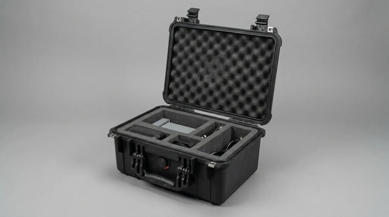
Projects frequently need both bullet and dome hardware, and buyers naturally want one case to carry everything, which creates a geometry compatibility problem.
Bullet cameras are long cylinders with an offset bracket, so the axial dimension dominates. Design the cavity for horizontal placement with axial location, leaving 8 to 12 mm of cushioning at each end and supporting the barrel in two semicircular cradles. A cradle wrap angle of 120 to 150 degrees works well, because a smaller angle creates point contact while a larger angle makes insertion awkward. Bracket assemblies should be cut into their own bores rather than tied to the camera body, since an unsupported overhanging bracket acts as a cantilever and amplifies shock.
PTZ and dome units are large spheres on ceiling plates. Their centre of gravity sits near the geometric centre, so in some respects they survive drops better than bullets, but their bubbles do not survive abrasion. The transparent cover usually carries a hard coat only a few micrometres thick, and any contact with a hard surface can leave a mark. Dome units therefore require a strict rule: the bubble must touch nothing at all, including the case wall, the insert and neighbouring items.
High-speed PTZ units hide one more problem in the gimbal drive. Many models have no mechanical brake when unpowered, so sustained vibration during transport lets the head swing slightly, and over a long trip the gears or belt can drift out of position. Follow the manufacturer instruction to place the unit in its transport position, usually locked upward or horizontal, and support it accordingly in the insert.
| Geometry | Typical envelope | Unit mass | Insert treatment | Special requirement |
|---|---|---|---|---|
| --- | --- | --- | --- | --- |
| Bullet camera | 200 to 400 mm long, 60 to 110 mm barrel | 0.6 to 2.5 kg | Two semicircular cradles, 120 to 150 degree wrap | Separate bore for bracket, thread cap on mount |
| Dome camera | 100 to 160 mm diameter, 60 to 100 mm high | 0.3 to 1.0 kg | Shallow recess, bubble facing up, one unit per bore | PE sleeve over bubble, no more than two tiers |
| High-speed PTZ | 220 to 230 mm sphere | 3 to 7 kg | Spherical cradle bowl, 10 mm clearance above | Place in transport lock position, locate body and base separately |
| Multi-sensor panoramic | 250 to 350 mm long, sensor array | 2 to 5 kg | Base plate bearing, optical windows facing up | Optical window must contact nothing |
When one case has to carry several geometries, a removable divider system is the practical answer. It splits the interior into physically independent bays first, then each bay receives its own cutouts, so packing a mixed shipment never requires a redesign. Details on divider retention and selection are in the removable divider system overview.
One material trap deserves a warning: do not wrap dome bubbles in ordinary PVC shrink film. Plasticisers in PVC migrate into polycarbonate and can make the bubble yellow and brittle over time, and PVC also generates significant static when rubbed. Acid-free tissue plus a PE sleeve costs about the same and carries far less risk.
4. NVRs and Storage Servers: Hard Drive Shock Comes First
If lenses fear slow abrasion and static load, hard drives fear instantaneous acceleration. The read/write head in a modern 3.5-inch drive flies only a few nanometres above the platter, roughly one ten-thousandth of a human hair. Any shock that creates a sudden relative velocity between head and platter can cause the head to scrape the surface, an event usually called head slap.
Two widespread misconceptions need clearing up. First, the free-fall sensor in a hard drive only functions while the drive is powered. It detects free fall and retracts the heads within tens of milliseconds, but during transport the drive is unpowered and the mechanism is completely inactive. Second, the 250 to 350 G non-operating rating describes the point at which the mechanical assembly does not come apart, not the point at which data remains intact. A meaningful share of post-transport drive failures appear as soft damage with reallocated sectors that pass an incoming functional test but degrade during service.
Shock and vibration isolation for recording hardware should follow four rules.
Suspension beats thicker foam. Simply adding foam thickness only shaves part of the shock peak. Suspending the drive cage or equipment bracket on elastomeric mounts inside the case moves the system natural frequency away from the dominant transport vibration band, which is what actually reduces resonant amplification. For palletised storage servers this matters a great deal.
Control the static compression. Work backwards from equipment mass to bearing area, and aim for 15 to 25 percent static compression in the EVA. Too little compression absorbs no energy, while too much compresses the foam into a solid that transmits shock and makes insertion difficult. Verify the ratio against the supplier compression curve rather than judging by feel.
One device, one cavity. Two units placed face to face will strike each other under vibration, and the contact surfaces are usually connector panels or ventilation openings. Keep 5 to 10 mm of foam wall between adjacent cavities.
Watch the drive axis. Most 3.5-inch drives tolerate higher shock along the platter axis than radially. If the platter plane can be oriented perpendicular to the dominant shock direction, which is normally the floor-to-ceiling drop axis, the protection margin improves noticeably.
| Storage medium | Operating shock | Non-operating shock | Transport sensitivity | Protection priority |
|---|---|---|---|---|
| --- | --- | --- | --- | --- |
| 3.5-inch HDD | 30 to 70 G (2 ms) | 250 to 350 G (2 ms) | Head slap, bearing damage, bad sectors | Suspension, controlled compression, isolated cavity |
| 2.5-inch HDD | 200 to 400 G (2 ms) | 800 to 1000 G (2 ms) | Same, higher thresholds | Same, thinner foam acceptable |
| Enterprise SSD | 1500 G (0.5 ms) | 1500 G (0.5 ms) | ESD, solder joint fatigue, power-loss risk | Dissipative liner, connector protection |
| Tape media | Model dependent | Model dependent | Humidity and magnetic fields | Stable climate, distance from magnets |
| Complete NVR with drives | Drive limited | Drive limited | Relative movement of drive and chassis | Fit anti-vibration cage before packing |
For NVRs that already have drives installed, the most neglected item in transport is the internal drive cage. Inexpensive spring-steel cages develop fretting wear under sustained vibration, which leads to intermittent SATA contact. If the batch will travel long distances or be transferred several times, fit an anti-vibration cage inside the chassis, or remove the drives and pack them separately before shipment. The second option costs assembly time on site but gives the best protection for the recorded data.
5. Power Supplies, PoE Switches and Cable Management
This group is often treated as unbreakable supporting hardware, yet it causes most of the scratch damage inside a case.
The problem with power adapters is concentrated mass in a small volume, combined with sharp metal prongs and cooling fins. A 48 V, 120 W adapter weighs 400 to 700 g, and if it sits directly against a camera body, the local force during a drop can dent the housing. The prongs can pierce a foam layer and press against a lens or bubble on the other side.
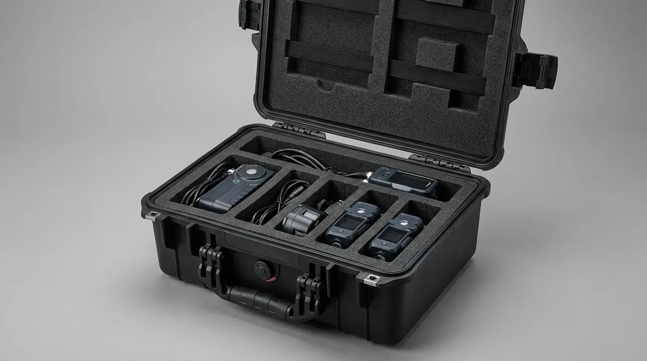
The correct approach is to place power equipment, cables, fasteners and tools together in a heavy bay that is physically separated from the optical bay and the drive bay. The heavy bay normally sits at the bottom layer or at the outermost edge of the top layer, so that even if the case lands on its side, heavy items cannot cross the foam wall toward fragile items.
Cable management has three rules. First, coil copper cable at a diameter no smaller than four times the cable outer diameter, and coil fibre patch cords at no smaller than ten times the outer diameter when static, because tighter bends impose permanent bend stress that shows up as added attenuation or a broken core. Second, secure each coil with ties until it behaves as a rigid assembly, since a loose bundle acts like a spring and hammers the case wall. Third, keep fibre end faces fully isolated from metal, using an individual PE bag inside a rigid spool.
If the scope includes lithium-battery UPS units or portable power packs, the compliance picture changes. Lithium cells normally require UN 38.3 transport testing plus documentation specified by the carrier, and sea freight also falls under IMDG classification and packing requirements for dangerous goods. Because that interacts directly with case design, see the hazmat transport case compliance notes.
| Bay | Contents | Insert form | Separation requirement |
|---|---|---|---|
| --- | --- | --- | --- |
| Optical bay | Lenses, bubbles, front window parts | Closed-cell EVA bored to diameter | PE hardboard to drive bay |
| Sensitive electronics bay | NVRs, switches, media converters | Individual cavities with elastomeric suspension | 10 mm or more of foam to heavy bay |
| Heavy bay | Power adapters, central supply, fasteners | Deep recess, 25 mm or more cushion below | Outermost layer of the case |
| Cable bay | Patch cords, fibre, mains leads | Coiled, tied, compartmentalised | Individual rigid spools |
| Accessory bay | Screws, anchors, glands | Compartmented box with lid | Physically separated from optical bay |
6. Lenses, Brackets and Small Parts Without Scratches
Small parts are the hardest group to control because there are usually dozens or hundreds of them and their shapes are irregular.
Screws, expansion anchors, cable glands, cable ties and connector caps placed loose in one bag will grind against each other under vibration and generate metal debris. Once that debris reaches an optical bay it becomes the abrasive particle described earlier. Small parts therefore need compartmented storage with a lid on the compartment box.
Brackets are the other underestimated item. Bullet mounts, pendant arms, pole clamps and swivel joints are not light, and they carry threaded interfaces and sharp corners. The correct treatment is a dedicated bore with a PE cap over every thread, and where brackets are stacked, interleave acid-free tissue so painted surfaces do not rub.
Magnets deserve a mention alongside drives. Magnetic hex bits, magnetic mounts and magnetic cable clips kept pressed against a hard drive for a long period are theoretically a risk to the servo information on the platter. The more practical problem in a workshop is that magnetic tools collect metal debris and then deposit it on the equipment when the case is opened. Keep magnetised tools in a separate tool bay or leave them out of the shipment entirely.
Labelling looks trivial but directly affects receiving efficiency. Put removable labels along the edge of each cavity showing model and quantity, and insist on a solvent-free removable adhesive, because residue from aggressive labels contaminates the foam and traps dust until the cavity becomes impossible to clean. For shedding rates and cleanliness control across insert materials, see the case foam material comparison.
7. Moisture and Static: The Real Failure Drivers Outdoors
Most people assume transport damage to surveillance equipment is mostly mechanical. In coastal, riverside and hot humid regions, moisture and static cause losses that are both more persistent and harder to detect.
Start with humidity. The inside of a camera lens is a semi-sealed volume formed by the barrel, elements, retaining rings and sealant. When relative humidity stays above 60 percent for long periods, mould spores on the glass and along the cement layer begin to germinate. The hyphae grow into the gaps between elements, first producing a faint scattering haze and after a few weeks a permanent network of traces that reduces contrast. This cannot be cleaned away; the lens assembly has to be replaced.
Container rain is the classic long-sea-voyage problem. The interior warms above 50 degrees Celsius during the day and falls below 20 at night, so airborne moisture condenses on the coldest surfaces, which are the goods. For a camera packed without moisture protection, that amounts to a sustained condensation cycle.
The basic configuration is sealed packaging plus desiccant plus a humidity indicator card. Desiccant selection depends on the scenario. Silica gel performs well above 40 percent relative humidity and can adsorb roughly 0.2 to 0.35 g of water per gram of desiccant as a rule of thumb, varying with temperature and humidity. Molecular sieve keeps strong adsorption capacity even at low humidity, which suits applications that must hold relative humidity below 20 percent for long periods. Montmorillonite clay is the cheapest option but has lower capacity and slower uptake, so it fits short domestic trips.
A reasonable starting quantity for a sealed case with 50 litres of internal free volume is 150 to 250 g of silica gel, intended to take internal relative humidity from 60 percent down to 45 percent over 30 days and hold it there. The phrase "rule of thumb" matters here, because the real requirement depends strongly on gasket performance, day-night temperature swing and how often the case is opened. Any estimate that ignores those factors can be wrong by a factor of several. The reliable method is to place a three-spot humidity indicator card and a data logger in the case, run one trip at the estimated quantity, read the record, and adjust the next batch accordingly.
Static is the second issue. CMOS image sensors are ESD-sensitive devices with human body model withstand voltages typically around 1 to 2 kV. A person walking, removing a jacket or rubbing packaging material in a dry environment easily accumulates several kilovolts. For complete units the housing provides some shielding and the risk is manageable, but refurbished units, stripped parts and bare boards must travel in dissipative packaging.
Dissipative materials are classified by surface resistivity. Conductive materials typically sit below 10^4 ohms, dissipative materials between 10^4 and 10^11 ohms, and insulators above 10^11 ohms. Equipment transport should use dissipative-grade liners and bags, which bleed static charge away slowly without putting highly conductive material close to powered circuitry. For case construction and material choice in this area, see the ESD shield case overview.
| Protection goal | Material or measure | Key parameter | Typical application |
|---|---|---|---|
| --- | --- | --- | --- |
| General dehumidification | Silica gel desiccant | Adsorbs roughly 20 to 35 percent of its own mass | Standard long-haul road freight |
| Sustained low humidity | Molecular sieve | Strong uptake at low humidity | Sea freight, cross-climate export |
| Visual humidity check | Three-spot indicator card | Colour change at 5, 10 and 60 percent | Any pack containing optics |
| Static bleed | Dissipative foam and bags | Surface resistivity 10^4 to 10^11 ohms | Bare boards, refurbished units |
| Condensation control | Sealed pack plus desiccant plus thermal buffer | Internal humidity at or below 50 percent | Ocean containers |
| Salt spray resistance | Stainless hardware with plated finishes | 48 to 96 hours neutral salt spray to GB/T 10125 | Coastal and island installations |
8. Protecting the IP67 Sealing Path in Transit
An outdoor camera survives rain because of a complete sealing system. That system normally has four segments: between the front window and the housing, usually an O-ring or a potting compound; the cable entry, with a sealing ring and a waterproof gland; the rear cover, closed by an O-ring and several screws at specified torque; and the pressure-equalisation vent, which uses an expanded PTFE membrane.
What these four segments share is an assumption that the assembly is finished and undisturbed. Transport is precisely the phase most likely to disturb them.
An O-ring is an elastomer, designed to operate at 20 to 35 percent compression. Sustained lateral squeeze inside a case flattens the cross-section into an oval that does not fully recover when the load is removed, so sealing contact pressure drops. The symptom is a camera that performs perfectly through the first three months of rain and then shows mist inside the front window when the wet season arrives.
Screw torque is equally vulnerable. In an assembly closed by several screws tightened in a star pattern, one screw loosening under vibration redistributes the contact pressure around the whole perimeter. Keep factory torque during transport and resist the temptation to tighten further as a precaution, because over-torque compresses the O-ring beyond its elastic range and produces the same permanent set as under-torque.
Glands and threaded openings need physical protection. The cable entry should retain its factory cap or a PE plug so foam debris cannot enter the gland body, and exposed threads such as the 1/4-inch or 3/8-inch camera base thread or the pendant mount on a PTZ unit should carry plastic caps so they cannot be chipped during handling. Once a thread develops a burr it will gall during installation, and there is no way to repair it on site.
The pressure-equalisation vent is the segment most often forgotten. Its membrane passes gas while blocking liquid water, and its pores are measured in micrometres. Dust or oil covering the membrane reduces its breathability, and in an environment with large day-night temperature swings the housing can no longer equalise quickly. The front window then sees repeated differential pressure cycles.
This leads into the case-level pressure problem. A cargo hold in cruise sits at roughly 0.7 to 0.8 bar absolute, and moving equipment from lowland warehouses to a high-altitude site creates a similar differential. A fully sealed case produces two consequences under such a load: opening it requires excessive force or a tool, and the gasket is repeatedly compressed until it takes a permanent set. The fix is a pressure equalisation valve that keeps the differential within what the gasket can tolerate. Valve selection and failure modes are covered in the case pressure equalisation valve technical note.
Receiving inspection also has a correct sequence. Check the outer case and gasket first, then the camera body and front window, then look for foreign objects in the O-ring groove, and only then power up for a functional check. Do not pressure-wash newly received units as a leak test. The dynamic pressure of a wash jet far exceeds the 1 metre static immersion condition, so the test itself can damage the seal and provides no valid information. IP67 means complete dust protection plus short-term immersion protection at 1 metre for 30 minutes, and it should be verified under the conditions defined in GB/T 4208 or IEC 60529.
9. Case Architecture: Hinges, Latches and Gaskets
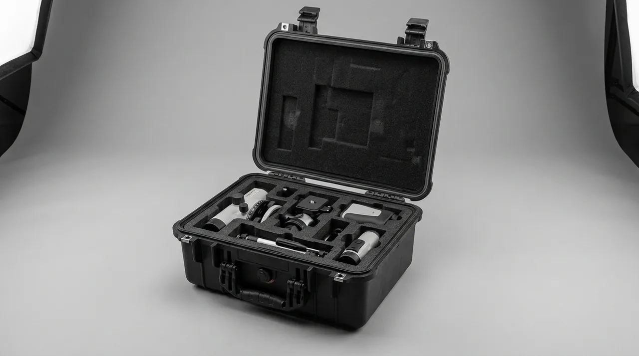
The shell sets the upper limit of the whole design, and the insert only carries equipment safely within that limit.
Four mainstream options exist, each with clear boundaries. Injection-moulded polypropylene copolymer is the most common choice for surveillance equipment today: uniform wall thickness, good dimensional stability, a wide service temperature range with typical short-term tolerance from minus 40 to plus 90 degrees Celsius, good chemical resistance, and the ability to mould reinforcing ribs and a gasket channel in one cycle. Blow-moulded polyethylene offers better impact and low-temperature performance but lower dimensional accuracy, which makes precise insert location harder; it suits heavy items that tolerate contact. Aluminium cases look professional and are stiff, which suits high-value short-haul and demonstration transport, but they are heavy, costly and need extra surface treatment for salt spray exposure. Timber cases suit palletised and very heavy loads with flexible dimensions, though export shipments require heat treatment or fumigation documentation.
The gasket is the part that determines water resistance. Expanded EPDM and silicone are the common materials. EPDM offers good weathering and low cost and dominates the market, while silicone holds elasticity better at low temperature and suits exports that must seal below minus 30 degrees Celsius. The critical design parameter is compression: the gasket section should be compressed 25 to 35 percent when the case is closed. Below that range the contact pressure is insufficient, and above it permanent deformation accelerates. The channel profile must match the gasket section so that closing force converts into sealing pressure rather than sideways extrusion.
Hardware selection should follow the operating environment. Zinc-plated and passivated steel is adequate for dry inland sites. Coastal and island projects should use 304 or 316 stainless steel verified by neutral salt spray testing to GB/T 10125, typically requiring no red rust at 48 hours and 96 hours for stricter specifications. Internally concealed hinges outperform exposed hinges, which deform easily on impact and trap salt and grit in their gaps. Cam-style latches maintain consistent preload and distribute gasket pressure more evenly around the perimeter than simple snap catches. For hinge, latch and gasket interaction, see the toolbox hinge, latch and seal design guide.
For impact rating, a case carrying surveillance equipment should reach at least IK08 under the GB/T 20138 or IEC 62262 framework, meaning it survives 5 joules of impact without functional damage. Palletised configurations also need a stacking check: at three to five tiers, the bottom case may see 200 to 400 kg of static load, which directly determines wall thickness and rib layout.
10. Custom Foam Inserts: EVA, PE, PU and Dissipative Options
Insert material sets the lower bound of protection. A strong case with the wrong foam still delivers damaged drives and scratched lenses.
EVA, an ethylene-vinyl acetate copolymer, is the default insert material for equipment cases. It is closed-cell, resilient, low-shedding and easy to machine, with density typically between 30 and 80 kg per cubic metre and hardness quoted on the Shore A or Shore C scale. Higher-density EVA suits load-bearing location features, while lower-density grades work as a cushioning transition layer. The weakness of EVA is long-term compression set, so avoid designing beyond 30 percent compression in equipment that is opened and repacked frequently.
Polyethylene foams, including cross-linked XPE and irradiation cross-linked IXPE, cushion strongly and rebound slowly, which makes them excellent sacrificial energy absorbers. The typical arrangement is a PE layer between the case floor and the EVA insert: the PE layer absorbs most of the drop energy while the EVA layer keeps equipment located. The combination clearly outperforms either material alone.
Polyurethane foam is open-cell with an excellent cushioning curve, but it absorbs moisture, sheds particles and traps dust. In any application where cleanliness and humidity matter, it is the wrong choice, even though it works acceptably for rough cushioning of industrial machinery.
Dissipative inserts are made by loading EVA or PE with conductive fillers such as carbon black or conductive fibre to bring surface resistivity into the 10^4 to 10^11 ohm dissipative range. Two caveats apply. Adding filler usually reduces mechanical performance, so fully dissipative liners should not carry primary structural load. Dissipative performance is also humidity dependent and surface resistivity rises in very dry conditions, so bare boards travelling through arid regions still need a dissipative bag as the primary barrier.
| Material | Typical density | Rebound behaviour | Shedding and moisture | Typical use | Main limitation |
|---|---|---|---|---|---|
| --- | --- | --- | --- | --- | --- |
| EVA foam | 30 to 80 kg/m3 | Good resilience | Closed-cell, low shedding | Primary bored location layer | Compression set over time |
| XPE and IXPE | 25 to 60 kg/m3 | Slow rebound, strong energy absorption | Closed-cell, no moisture uptake | Sacrificial base cushion | Lower location accuracy than EVA |
| PU foam | 20 to 40 kg/m3 | Soft cushioning | Open-cell, absorbs water, sheds | Rough cushioning in non-clean areas | Unsuitable for optics and drives |
| Dissipative EVA | 40 to 70 kg/m3 | Slightly below standard EVA | Closed-cell, low shedding | Bare boards and refurbished units | Performance varies with humidity |
| PE hardboard, 3 to 5 mm | Not applicable | Rigid | No shedding | Bulkhead between bays | No cushioning capability |
CNC routing is the main production method for surveillance inserts, supported by waterjet cutting and die cutting. CNC holds tolerances of plus or minus 0.5 mm and suits mixed, low-volume orders, while die cutting is cheaper per piece at scale but slow to adapt when a model changes. Where the equipment line is expected to iterate, use a layered, replaceable design: make the bored layer a separate module and keep the base and lid cushions common, so a model change only requires a new bored layer.
11. Transport Testing and Acceptance
Design work produces a paper conclusion; only testing confirms it. Three test frameworks cover surveillance cases, and the choice follows the transport mode and the destination market.
The ISTA series suits single packs and parcel distribution. ISTA 2B covers partially simulated performance testing of single packaged products, while ISTA 3A covers general simulation for parcel delivery systems. Both include drop, vibration and stacking stages, with severity graded by packed weight and shipping form.
The GB/T 4857 series is the framework most often cited in domestic engineering. GB/T 4857.5 defines the drop test method and GB/T 4857.23 defines the random vibration method. For domestic projects it is common and far more reliable to state in the purchasing specification that drop testing follows GB/T 4857.5 and random vibration follows GB/T 4857.23, rather than writing a vague requirement to pass transport testing.
ASTM D4169 applies to performance testing organised around a distribution cycle, and combinations such as DC13 are frequently used for air freight and palletised freight. North American customers often name this standard directly.
MIL-STD-810H Method 516.8 for shock and Method 514.8 for vibration may also be cited as test method sources, with one clear qualification: they are environmental test methods and do not constitute military certification. Treating them as a source of test conditions rather than a certification label is the professional way to phrase it.
A complete acceptance process includes functional checks both before and after testing, and the checklist must reach the hidden failure modes described earlier.
| Stage | Checks | Acceptance basis |
|---|---|---|
| --- | --- | --- |
| Pre-test | Lens appearance, dome bubbles, powered self-test, full SMART readout | Establish baseline per unit |
| During test | Case displacement, gasket extrusion, insert movement | Visual inspection with timed records |
| Post-test | Shell deformation, gasket permanent set, bore dimension change | Measure against baseline |
| Functional retest | Camera imaging including flare and ghosting, drive recognition and bad sector scan | 100 percent retest per unit |
| Teardown sample | O-ring section ovality, thread burrs, gland contamination | Two or three units per batch |
Batch quality control should follow GB/T 2828.1 sampling, with critical characteristics such as sealing surface condition, insert bore dimensions and hardware salt spray classified as major defects, and cosmetic scratches as minor. For sampling scheme and acceptance design, see the custom case acceptance and AQL guide.
One caution: never fabricate test data. Suppliers can realistically provide material certificates, dimensional reports and test reports produced to a named standard, but not certification to a military specification nobody actually applied. Writing precise requirements into the specification and obtaining data from real test runs is worth far more than a certificate that looks impressive.
12. How JUNZHIJIA Delivers These Cases
JUNZHIJIA approaches surveillance transport protection by locking down three things: a device envelope library, parametric insert drawings, and batch consistency control.
The envelope library solves repeated design work. Surveillance models iterate quickly, and one customer may use different bullet, PTZ and NVR models across projects. JUNZHIJIA maintains a cutout parameter library covering mainstream brands and form factors, so once a customer supplies equipment envelope dimensions the values can be applied directly, reducing repeat sampling and keeping bores consistent between batches of the same model.
Parametric insert drawings solve the gap between documentation and physical reality. Each drawing specifies bore position, bore diameter and depth tolerances, load-bearing surface locations, and separation requirements for every bay. Customers can fold the drawing straight into their own packing work instruction. Requirements such as transferring lens load through the barrel cylinder, isolating each NVR in its own cavity, or inserting PE hardboard between the optical and drive bays appear on the drawing as dimensions and material callouts rather than verbal agreements.
Batch consistency control solves long-term supply stability. Case colour and wall thickness, gasket hardness and compression, and EVA density and hardness are the parameters most prone to drift between production runs. JUNZHIJIA retains reference samples per batch with recorded key parameters so customers can compare on a batch change and avoid problems such as a gasket that has quietly become harder with no traceable cause.
Delivery is available as OEM, following a customer's existing design, or ODM, where JUNZHIJIA develops the structure and insert design. Wholesale, distribution and worldwide supply are supported, along with material certificates, dimensional inspection reports and third-party testing to named standards where a project requires them.
13. Typical Configurations and Case Size Recommendations
The matrix below translates the preceding rules into starting points for common project sizes. Internal dimensions and insert concepts are initial recommendations and still require verification against measured equipment envelopes.
| Project scenario | Equipment list | Suggested internal size | Insert concept | Estimated gross mass |
|---|---|---|---|---|
| --- | --- | --- | --- | --- |
| Small retail, 4 to 8 channels | 4 bullets, one 4-bay NVR, 4 lenses, power supply | 550 x 400 x 220 mm | Bullets horizontal in two cradles on top, NVR in a single cavity below with a PE layer | 12 to 18 kg |
| Campus, 16 to 32 channels | 8 domes, 2 NVRs, switch, cabling | 700 x 500 x 300 mm | Shallow recess per dome, NVR and switch in separate bays, dedicated cable bay | 25 to 35 kg |
| PTZ deployment | 2 high-speed domes, brackets, central supply | 600 x 450 x 350 mm | Spherical cradle bowl with elastomer below, brackets in a separate bay | 22 to 30 kg |
| RMA return shipment | Bare boards, stripped units | 450 x 350 x 200 mm | Fully dissipative liner, PE hardboard bulkhead, humidity indicator card | 6 to 10 kg |
| Export pallet | Multiple cases on a pallet | Matched to pallet footprint | IP67 case with equalisation valve, moisture barrier over the pallet with desiccant | Configuration dependent |
Three practical rules help with selection. First, allow 15 to 20 percent of internal volume for insert and cushioning, and never buy a case by matching it to equipment dimensions alone. Second, where packed mass exceeds 25 kg, prefer a wheeled and tow-handle model or split the shipment into two cases, because manual handling drops are the leading killer of hard drives. Third, for export projects confirm hardware salt spray requirements and whether any timber components are involved, so that fumigation issues do not create extra cost at the destination port.
Frequently Asked Questions
Q: Why does a camera show a fixed ghost image after transport when there is no visible damage?
A: The cause usually sits in the cemented lens group or the optical filter inside the assembly rather than on any visible surface. Two mechanisms dominate. The first is stress damage, where the insert bore transfers load through the apex of an element, so sustained stacking pressure slightly deforms the barrel and shifts the layers of the cemented group, adding reflections at the cement interfaces that appear as a fixed ghost or flare. The second is heat combined with stress, because above roughly 55 degrees Celsius the modulus of resin cement drops and any stacking load or vibration applied at that moment can separate the bond locally. To diagnose it, image a uniform light source through the same lens at several apertures and watch whether the ghost moves. A ghost fixed at the same point on the image plane generally points to the cement layer or the filter. The fix is to transfer load through the barrel cylinder, keep at least 2 mm of clearance in front of the outermost element, and avoid leaving cases on the top layer of a container during summer.
Q: Hard drives are rated above 250 G non-operating shock, so why do bad sectors appear after shipping?
A: That 250 to 350 G rating at 2 ms describes the load at which the mechanical assembly survives a single shock event, and it does not guarantee that head and platter never touched. The head flies only a few nanometres above the surface, so certain frequency components in a shock waveform can momentarily bring it into contact and leave a very shallow mark. Such damage usually produces a clean incoming test and only later shows up as a rising count of pending sectors. A second cause is repetition. A single 200 G event may be harmless, but several hundred short 20 to 50 G events accumulated over hours of vibration cause micro-wear between head and platter. The design objective is therefore not to stay below the published threshold but to reduce both the peak and the number of shock events reaching the drive. Suspending the device on elastomers, increasing the energy-absorbing layer, keeping the centre of gravity low and limiting packed mass together deliver more than simply adding foam thickness.
Q: An outdoor camera obviously survives rain once installed, so why protect its sealing surfaces during transport?
A: Because outdoor service and transport load the seal in completely different ways. On a pole the sealing path sees only static rain pressure and wind load, all from one direction and at low magnitude. During transport it faces compression from multiple directions, sustained stacking load and the acceleration of a drop, any of which can exceed the design condition. The most common damage is an O-ring squeezed into an oval section that does not recover, leaving local sealing pressure short of the requirement. Next is a single screw loosening under vibration in a multi-screw closure, which unbalances pressure around the whole perimeter. Neither fault causes immediate failure. Both appear in the first wet season after installation. Since replacing a camera already mounted at height costs far more than packaging, keep factory protective caps and thread plugs in place during transport and prevent any direct compression of sealing surfaces. A further consideration is the site transfer itself, because a unit unpacked roughly and carried to a storeroom before installation absorbs the same kind of abuse a second time, so retention and handling instructions belong in the packing list as well as in the case design.
Q: How many grams of desiccant should actually be used, and is there a formula that can be applied directly?
A: There is no formula that can be applied unconditionally, but a rule of thumb provides a starting point that is then calibrated by measurement. The variables are internal free volume, gasket performance, transit duration, day-night temperature swing and how often the case is opened. A common starting calculation uses 300 to 500 g of silica gel per cubic metre of sealed volume, which for 50 litres of free volume gives about 15 to 25 g. That figure only holds for a well-sealed case on a road trip of two weeks or less. For sea freight with large temperature swings, or a case whose gasket leaks slightly, the quantity must be scaled up by a large factor. The dependable method is to place a three-spot humidity indicator card and a data logger inside, run one shipment at the estimated quantity, read the record afterwards, and set the next batch from that evidence. JUNZHIJIA recommends running this measurement once on the first shipment and then fixing the result as the packing standard for that project.
Q: Is dissipative packaging only needed for bare boards, or can complete units ship without it?
A: Complete units carry lower risk than bare boards, but the risk is not zero. CMOS image sensors typically withstand only 1 to 2 kV under the human body model, while a person walking and rubbing packaging material in a dry environment can accumulate several kilovolts. In a finished unit the metal housing and internal grounding provide some shielding, but if the housing has been opened during service, if connector covers have been removed, or if the product is a plastic-bodied dome camera, static can still enter through exposed conductors such as the network port, BNC connector or power input. The highest-risk cases are return shipments and equipment moved repeatedly on site. The recommended practice is a dissipative PE bag as a second barrier around complete units, and a fully dissipative liner with a dedicated cavity for refurbished units and bare boards. Liner surface resistivity should fall within the 10^4 to 10^11 ohm dissipative range.
Q: Should the case have a pressure equalisation valve, and when is it mandatory?
A: It depends on the transport mode and the destination altitude. A fully sealed case under a significant pressure differential creates two problems: it is hard to open, and the gasket takes a permanent set from repeated compression. A cargo hold at cruise sits near 0.7 to 0.8 bar absolute, which is roughly 200 to 300 mbar below ground level pressure, and moving goods from lowland storage to a high-altitude site produces a similar differential that reverses each way on the return leg. The decision rule is straightforward. Fit a valve whenever the route includes air freight, high-altitude road transport, or a temperature span above 30 degrees Celsius that would significantly change internal pressure. The valve allows gas to pass slowly while preserving IP67 water resistance, holding the differential within what the gasket can tolerate. Note that a valve supplements rather than replaces correct gasket compression design. On units destined for tropical projects, also verify that the vent membrane has not been painted over or covered by a protective film during packing, because that defeats the equalisation function while leaving the valve looking perfectly serviceable.
Q: How should transport protection be written into a purchasing specification to prevent disputes later?
A: The key is to express requirements as measurable, reproducible clauses rather than adjectives. At minimum, cover five areas. First, insert material and parameters: material type, density, hardness range, bore dimensional tolerances and load-bearing locations. Second, sealing requirements: the protection rating and the standard number used to verify it, plus gasket material and compression range. Third, testing: which standards, which test items, and which functional checks before and after. Fourth, sampling and judgement: a sampling plan to GB/T 2828.1 with major and minor defect classification. Fifth, delivery documents: whether material certificates, dimensional reports or third-party test reports are required. Also name the insert drawing as a deliverable, so the design intent is fixed in dimensions rather than conversation. If damage is disputed later, dimensional measurement and functional retest can then locate the cause quickly instead of leaving the parties trading opinions. It also helps to record the case serial number and photograph every bay at the moment of packing, because a photographic packing record is the fastest way to prove that a unit left the factory correctly located and undamaged.
Q: One case has to carry bullet cameras and a high-speed PTZ dome, so how do I stop them interfering?
A: The robust approach is to cut the interior into physically independent bays with a removable divider system first, then apply dedicated cutouts inside each bay. The bullet bay uses horizontal placement in two semicircular cradles with a wrap angle of 120 to 150 degrees and 8 to 12 mm of cushioning at each end. The PTZ bay uses a spherical cradle bowl that supports as much of the lower hemisphere as possible and leaves at least 10 mm of clearance above, so the sphere cannot bounce during a drop. Between the two bays keep a solid foam wall no thinner than 10 mm, and never cut a connecting channel through it. Place the heavy PTZ dome near the geometric centre rather than in a corner, and alternate heavy and light bays so the overall centre of gravity does not project near the case edge, where rotational acceleration on impact would rise sharply and stress both hard drives and gimbal mechanisms.
Conclusion and Further Reading
Transport protection for surveillance equipment means turning uncertainty into parameters: keep particles away from optics, keep pressure off optical surfaces, reduce both the peak and the count of shocks reaching a hard drive, and leave sealing faces undisturbed. Settling that at the packaging stage costs far less than reworking it on site.
Further reading