

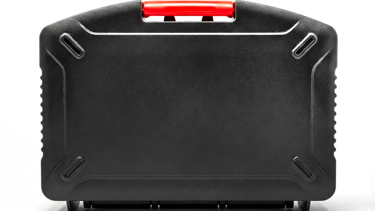
An electrode coating machine is the core front-end asset of a lithium cell line. A single unit carries hundreds of precision parts: the slot die lip gap is measured in microns, the dryer nozzle face is held flat to within a fraction of that, and the tension roller surface texture controls coating thickness consistency. When that machine is shipped, relocated, exported or returned for repair, those parts travel thousands of kilometres and pass through multiple handling steps. One impact, one damp night at sea, one dust particle can turn a ready-to-run delivery into weeks of on-site rework.
Coating dies, dryer nozzles and tension rollers are parts where precision equals value, so protection is not about making the box thicker; it is about locking cleanliness, flatness, surface texture and static control into separate cavities and making the whole journey verifiable. JUNZHIJIA combines compartmented interiors, cleanroom liners and pressure-equalisation design so every coating component arrives ready to install.
Table of Contents
- Why Electrode Coating Machine Components Need Dedicated Cases
- Coating Die Heads: Cleanliness and Lip Protection in Transit
- Dryer Nozzles: Flatness Retention and Blockage Prevention
- Tension Rollers: Preserving Surface Roughness and the Roll Face
- Web Guiding Components and Sensor Protection
- Cleanliness Class and Particle Contamination Control
- Case Materials and Structural Design
- Sealing Design: IP65/IP67 and Pressure Equalisation
- Cushioning Liners: EPE, EVA, PE and IXPE Selection
- Anti-Static and Cleanroom Liners
- Latches, Hinges and Stacking Load
- Temperature, Humidity, Salt Spray and Transport Testing
- Customisation, OEM/ODM and Acceptance Criteria
- Frequently Asked Questions FAQ
- Conclusion and Related Reading
Why Electrode Coating Machine Components Need Dedicated Cases
An electrode coating machine spreads cathode or anode slurry uniformly onto copper or aluminium foil. The pneumatic and mechanical precision of its upstream components maps directly onto cell consistency. The slot die lip gap typically sits in the tens to hundreds of microns; once the lip is scratched or plastically deformed, the coating shows streaks, heavy edges or bare spots, and the finished cell is downgraded or scrapped. Dryer nozzles and air knives push hot air onto the wet coating, so the straightness of the nozzle face and the uniformity of the discharge slot decide the drying rate profile. A small knock creates local over-drying or residual solvent.
What these parts share is high value, low volume, heavy unit weight, sensitive surfaces and no tolerance for compromise. They are neither consumable fasteners that can be swapped casually nor castings that tolerate a light bump. Many builders still ship dies and nozzles bare in wooden crates wrapped in bubble film, and the result is re-lapped lips, re-calibrated nozzles and re-cleaned ovens before the line can run.
A dedicated case turns cannot-compromise into can-verify. The shell resists stacking and forklift impact, the liner locates each part in its own cavity so components cannot strike each other, cleanroom and anti-static layers control particles and charge, and sealing plus pressure equalisation defend against sea-freight humidity and air-freight pressure swings. For equipment where a single mis-load is extremely costly, the case is part of the delivery schedule. The compartmented logic used for EV Battery Tray & Mold Cases in the same front-end equipment family can be read together with the approach described here.
Failure modes and countermeasures
| Failure mode | Typical cause | Consequence | Countermeasure |
|---|---|---|---|
| --- | --- | --- | --- |
| Lip scratching | Part-to-part contact, hard liner | Streaks and bare spots | Soft clean liner plus isolated cavity |
| Flatness drift | Stacking load, transport vibration | Uneven drying, solvent residue | Rigid support rail plus limited cushion |
| Roll face degradation | Relative sliding, trapped debris | Coating thickness variation | Axial locking plus dust-free wrap |
| Particle contamination | Paper, wood or foam debris | Internal short-circuit risk | Cleanroom liner plus double bagging |
| Moisture corrosion | Condensation from day-night cycles | Oxidation, precision drift | IP65/IP67 plus desiccant |
| Static attraction | Triboelectric charging in dry air | Dust pick-up, sensor damage | Conductive liner plus earth terminal |
Coating Die Heads: Cleanliness and Lip Protection in Transit
The slot die is the most delicate component on the coating line. Its body is usually stainless steel with internal manifolds and cavities, while the exposed lip face is mirror-lapped to roughness values around Ra 0.02 microns. Moisture or chloride-bearing contact produces pitting; a small plastic deformation at the lip is enough to destroy coating uniformity, and such deformation usually cannot be corrected on site, only re-lapped at the factory.
The first move in transport protection is to release assembly stress. After the die comes off the line, locating pins and adjusting bolts should be released as specified, and inlet and outlet ports sealed with dedicated plugs so residual slurry cannot dry inside or absorb moisture. The second move is independent lip protection: the lip must never rest on a hard surface. Wrap it in a clean PE bag or cleanroom non-woven, then support it in a contoured EVA or PE cavity so the lip is suspended with minimal load.
Die mass is usually concentrated low in the body, so the case needs a bottom load beam that carries weight straight into the base and pallet rather than through the liner walls. For wide dies longer than one metre, at least three axial supports should be provided so vibration cannot bow the middle. Adjustment wheels, sensor connectors and heater terminals are protrusions that need their own relief pockets to avoid concentrated vibration stress.
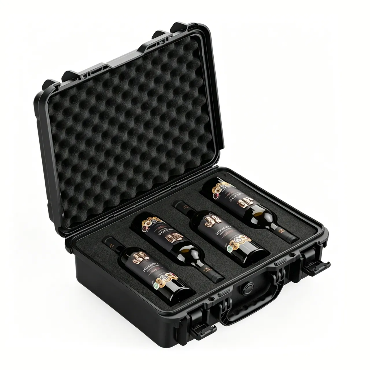
A die is a long-lead purchase, and many customers hold only one spare during commissioning. To cut rework risk, place a temperature-humidity card and an impact label inside the case and put the opening inspection flow into the shipping documents. Precision die faces of the same family are protected in Aluminum Extrusion Die Cases, whose face support and location methods are a useful cross-reference.
Die transport protection checklist
| Item | Requirement | Common gap |
|---|---|---|
| --- | --- | --- |
| Manifold sealing | Dedicated plug plus clean stopper | Tape only |
| Lip wrapping | Clean PE or non-woven | Ordinary bubble film |
| Cavity forming | Contoured EVA/PE, plus/minus 1 mm | Generic square slot |
| Axial support | At least 3 points, spacing up to 400 mm | One at each end |
| Protrusion relief | Dedicated pockets | Pressed into the liner |
| Recording device | Humidity card plus impact label | None |
Dryer Nozzles: Flatness Retention and Blockage Prevention
Dryer nozzles run across the full web width, with discharge slots typically between 0.5 and 2 millimetres. Face straightness and slot uniformity set the cross-web drying profile. Nozzles are usually welded or precision-formed parts up to one or two metres long with limited stiffness, which makes them the most likely component to suffer hidden deformation in transit.
Nozzle failure is progressive. A slight bow shows nothing at first, but it shifts the air volume distribution and produces local over-drying, edge curl or residual solvent. Such problems are extremely hard to trace during commissioning and are often found only when web inspection reports an abnormal thickness curve. The priority is therefore not impact resistance but bow resistance.
In the design, the nozzle should be carried along its length on rigid support plates that are themselves rigidly connected to the case base, forming simple or continuous support so no section is left spanning freely. The discharge lip should face upward or sideways and must never rest downward under load. If the nozzle carries flanges or mounting holes, locate it with pins so it cannot move fore and aft during transport.
Blockage prevention is the second priority. Nozzle channels are long and narrow, so packaging debris, foam granules or dust entering during transit will reduce local air volume after assembly. Seal the discharge slot with a clean strip or a dedicated shroud before dispatch and bag the whole part. For models with an adjustable damper, set the damper fully open and lock it so vibration cannot shift the mechanism.
Burner nozzles and valve trains belong to the same slender-precision family. Burner & Nozzle Cases place similar emphasis on sealing and cleaning narrow channels, and their plugging approach transfers well.
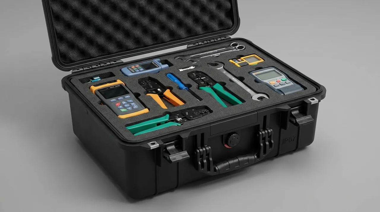
Recommended nozzle flatness protection parameters
| Parameter | Recommended value | Note |
|---|---|---|
| --- | --- | --- |
| Support spacing | Up to 400 mm | Prevents self-weight sag |
| Lip orientation | Upward or sideways | Never face down under load |
| Slot sealing | Clean strip or shroud | Keeps particles out |
| Individual wrapping | Clean bag | Dust and scratch barrier |
| Axial location | Pin or stop block | Prevents creep |
| Damper state | Fully open and locked | Prevents mechanism shift |
Tension Rollers: Preserving Surface Roughness and the Roll Face
The surface roughness of tension rollers and idler rollers is an invisible variable in coating thickness consistency. Roll faces are grit-blasted, chrome-plated or ceramic-coated to roughness values usually between Ra 0.1 and Ra 0.8 microns, which stabilises foil tension and provides controlled friction. Once a roll face is scratched, torn or contaminated, it leaves periodic marks on the web and can push thickness out of tolerance.
The most common damage to rollers in transit is not impact but relative sliding. If a roller is not locked both axially and radially inside its liner, vibration makes the roll face rub repeatedly against the liner and produces fine scratches. The core of the design is therefore all-direction constraint: a V-shaped or semi-circular formed slot supports the roll face radially, a stop block or end face limits it axially, and a clean dust-free cloth or PE film isolates the face from the liner.
For rollers with softer plated layers, bag the whole part in a clean anti-static bag and keep it out of the same cavity as other metal parts. When several rollers share one case, use a tiered rack so each roller is supported independently, and never stack them in contact. Bearing housings, end caps and couplings are protrusions that need relief so the end faces do not carry load.
Roll face roughness is a dispatch specification, and post-shipment re-measurement often shows a slight drop, so an appearance and roughness spot check belongs in the acceptance flow. Roller protection follows the same logic as Conveyor Roller & Parts Cases, where formed slots and axial locking are the core measures.

Roller component protection points
| Area | Risk | Measure |
|---|---|---|
| --- | --- | --- |
| Roll face | Scratching, tearing | Formed slot plus dust-free cloth |
| Bearing housing | End face load | Dedicated relief pocket |
| Coupling | Vibration loosening | Separate packaging |
| Axial direction | Creep and rubbing | Stop block location |
| Plated layer | Galvanic corrosion | Anti-static clean bag |
| Multiple rollers | Mutual impact | Tiered rack |
Web Guiding Components and Sensor Protection
Web coating depends on edge position control, whose actuators, servo motors, encoders and edge sensors are distributed along both sides of the machine. These parts are small, precise and contain electronics, so the protection logic differs from purely mechanical parts: mechanical parts fear deformation, electronics fear static, moisture and vibration that loosens connectors.
If a guiding actuator screw or linear rail takes a lateral shock in transit, ball indentation can occur and increase backlash. Lock the actuator in its retracted or mechanically locked position and brace the moving end with a support block so inertia cannot strike the limit. Protect motor shaft extensions with sleeves, and place encoders and sensors in separate anti-static bagged cavities.
Edge sensors, whether infrared or CCD based, have optical windows. A scratched or smeared window shifts calibration. Cover the window with anti-static film and control relative humidity with desiccant inside the case. Cap all connectors so dust cannot enter the contacts. Where sensors contain batteries, declare them separately under transport regulations and insulate them properly.
Electronic components are static sensitive, so a conductive liner and an earth terminal are recommended for the whole case. Combined with the precision fit practices in Bearing & Gearbox Cases, this covers mechanical accuracy and electrical safety together: constrain the mechanical axis and drain the charge at the same time, then verify both at acceptance.
Guiding and sensor protection matrix
| Component | Main risk | Protection |
|---|---|---|
| --- | --- | --- |
| Actuator screw | Ball indentation | Mechanical lock plus support block |
| Servo motor | Shaft end impact | Shaft sleeve plus isolated cavity |
| Encoder | Vibration loosening | Anti-static bag plus cushion |
| Edge sensor | Window scratching | Anti-static film plus desiccant |
| Connector | Dust in contacts | Protective cap |
| Cable | Bending damage | Coil at large bend radius |
Cleanliness Class and Particle Contamination Control
Coating cleanliness requirements far exceed ordinary machining. A microscopic particle on the web can pierce the separator and create an internal short-circuit risk, so coating areas are usually controlled to ISO 14644-1 Class 7 to Class 8, equivalent to the older US Federal 209E ten-thousand to hundred-thousand range, with tighter targets at critical stations on leading lines.
The interior cleanliness of a transport case must serve the final assembly requirement, which means the liner itself cannot be a particle source. Ordinary EPS foam, wooden pallets and corrugated paper debris are classic dust generators and should never contact the parts. Use cleanroom-grade PE, EVA, IXPE or clean foam, and wipe the cavity before loading.
Double packaging is an effective way to control particle contamination: bag the component first, place it in the formed cavity, then line the whole case with a cleanroom layer. Loading and unloading should happen in a cleanroom or a temporary clean booth so the box is not contaminated the moment it opens. For high-cleanliness dies and nozzles, include a cleanliness test patch and evaluate the interior level after arrival.
Cleanroom equipment shares this logic. Cleanroom Equipment & Filter Cases offers reusable packaging and verification methods for filters and instruments that can be adapted directly to coating components.
Cleanliness control measures
| Stage | Measure | Objective |
|---|---|---|
| --- | --- | --- |
| Liner material | Clean PE/EVA/IXPE | Low particle shedding |
| Component wrap | Double clean bag | Particle isolation |
| Cavity cleaning | Wipe before loading | Remove residue |
| Loading environment | Cleanroom or booth | Avoid recontamination |
| Process monitoring | Cleanliness patch | Quantifiable assessment |
| Banned materials | Wood debris, EPS, paper | Eliminate sources |
Case Materials and Structural Design
Case material for electrode coating components must balance stiffness, weight, weather resistance and cleanliness. Common options include high-density rotationally moulded PE, injection-moulded PP, magnesium-aluminium frame cases and stainless steel bodies, and the choice depends on part weight, transport mode and cleanliness class.
Rotomoulded PE offers uniform wall thickness, good impact resistance and waterproofing, suiting medium parts handled frequently. Injection-moulded PP gives tight dimensional accuracy and a clean interior, suiting standardised volume parts. Magnesium-aluminium frames have an excellent strength-to-weight ratio for long dies and nozzles. Stainless steel resists corrosion and cleans easily, suiting high-cleanliness or frequently sanitised items. For parts above 150 kilograms, prefer a frame case shipped palletised.
Structurally, the case should divide the work between an outer frame that carries load and a liner that locates: the frame resists stacking and forklift impact, while the liner constrains and cushions the component in six directions. The base needs forklift slots or feet, and the lid needs ribs to prevent stack collapse. For very long parts, a clamshell or drawer design makes lifting and assembly easier.
Case material selection matrix
| Option | Strength/weight | Waterproofing | Cleanliness | Suitable parts |
|---|---|---|---|---|
| --- | --- | --- | --- | --- |
| Rotomoulded PE | Medium/medium | Excellent | Good | Medium dies, sensors |
| Injection PP | Medium/light | Good | Excellent | Small precision parts |
| Mg-Al frame | High/light | Good | Excellent | Long dies, nozzles |
| Stainless steel | High/heavy | Excellent | Excellent | High-cleanliness parts |
| Composite panel | Medium/medium | Fair | Fair | Returnable short haul |
Sealing Design: IP65/IP67 and Pressure Equalisation
Many coating components travel by sea or air, so sealing decides whether the interior gets damp or suffers condensation corrosion. Ingress protection is judged under IEC 60529 or the national standard GB/T 4208. IP65 means dust-tight and resistant to water jets, while IP67 means dust-tight and unaffected by short immersion under specified conditions. For sea freight or open-yard transfer, IP65 should be the floor and IP67 is advisable for long, humid journeys.
Sealing relies on three lines of defence: the gasket on the mating faces, even clamping force from the latches, and seals at cable or air-line entries. Use weather-resistant silicone or EPDM gaskets with sufficient contact width and compression. Latch count and spacing must keep pressure even around the whole perimeter, otherwise a local warp becomes a water path.
Pressure equalisation is the other sea and air freight issue. A sealed case develops an internal-external pressure differential with temperature or altitude change; forced opening can draw in moisture, and negative pressure can deform the gasket. A waterproof breather valve lets air pass while blocking liquid water, so internal pressure tracks the environment and the moisture-inrush effect at opening is avoided. For long-haul dies and nozzles, fit a breather valve as standard and leak-test the assembled case.
Protection rating and scenario matching
| Rating | Capability | Typical transport | Suggested parts |
|---|---|---|---|
| --- | --- | --- | --- |
| IP54 | Dust and splash | Short road haul | Standard structural parts |
| IP65 | Dust and water jets | Long road or rail | Dies, rollers |
| IP67 | Dust and short immersion | Sea freight, open yard | Nozzles, sensors |
| IP68 | Dust and continuous immersion | Special duty | Special-requirement parts |
Cushioning Liners: EPE, EVA, PE and IXPE Selection
The cushioning liner decides the acceleration peak a component sees under vibration and shock. EPE, EVA, PE foam and IXPE are the four common materials, with clear performance differences, and selection should combine part weight, sensitive faces and cleanliness requirements.
EPE has low density, good resilience and low cost, suiting large-area pads and void fill, but its surface is soft and shear resistance is moderate, so it should not carry heavy parts directly. EVA offers adjustable hardness and density, excellent formability and a fine surface, suiting contoured cavities and precision support, and it is a common choice for die and nozzle liners. PE foam is harder, closed-cell and water resistant, suiting load bearing and moisture protection. IXPE has fine, uniform cells, a flat surface and very low shedding, combining cushioning with cleanliness for high-cleanliness parts.
Liner design should follow a soft-hard layering principle: the layer touching the component is soft and low-shedding, the load-bearing layer is harder, and an energy-absorbing pad can sit between the liner and the shell. For parts above 50 kilograms, run a drop or impact simulation and confirm the liner keeps acceleration within the component limit.
Cushioning material comparison
| Material | Density | Resilience | Formability | Shedding | Typical use |
|---|---|---|---|---|---|
| --- | --- | --- | --- | --- | --- |
| EPE | Low | Excellent | Good | Medium | Fill, large-area cushion |
| EVA | Medium | Good | Excellent | Low | Contoured cavities |
| PE foam | Medium-high | Fair | Fair | Low | Load bearing, moisture |
| IXPE | Medium | Good | Excellent | Very low | High-cleanliness parts |
| Composite | Adjustable | Good | Excellent | Low | Large cavities |
Anti-Static and Cleanroom Liners
Static is an underrated threat to coating components. In dry air, foam rubbing against plastics generates thousands of volts, which attracts airborne particles and holds them firmly on a die lip or sensor window. For guiding sensors with electronics, electrostatic discharge can damage circuits directly. The liner must therefore be clean and static-dissipative at the same time.
Anti-static liners usually use conductive foam or anti-static PE/IXPE with a surface resistance between 10^6 and 10^9 ohms, combined with an earth terminal to drain charge. A metal frame can serve as the earth path directly; a plastic case needs a conductive layer embedded in the liner with an earth tab brought out. Bag the component in an anti-static bag first, then place it in the anti-static cavity.
Cleanliness and static control are often required together, so choose materials that are both low-shedding and anti-static, and avoid ordinary black conductive foam that crumbs. Loading staff should wear clean gloves and a wrist strap to limit human static and skin flakes.
Anti-static liner technical requirements
| Parameter | Recommended range | Note |
|---|---|---|
| --- | --- | --- |
| Surface resistance | 10^6 to 10^9 ohms | Dissipative range |
| Earth path | Continuous layer plus tab | Charge drainage |
| Shedding | Low | Protects optical faces |
| Wrapping | Anti-static inner bag | Double isolation |
| Operator practice | Wrist strap and gloves | Controls body charge |
| Verification | Surface resistance test | Pre-delivery sampling |
Latches, Hinges and Stacking Load
Latches and hinges are the weak points of a protective case and a frequent source of transport incidents. Latches must supply enough clamping force to deform the gasket evenly while resisting vibration self-release over long journeys. Hinges must carry repeated opening and lid self-weight, with anti-detach pins.
For heavy component cases, use multi-point latches or draw latches with take-up travel, arranged symmetrically across the case diagonals. Latch bodies can be stainless or zinc-plated steel with anti-corrosion treatment. Prefer concealed or reinforced hinges so exposed hardware cannot be deformed by forklift contact.
Stacking load is a hard requirement in containers and warehouses. Mark the stacking layers and maximum load, and design lid ribs and corner posts to pass the upper load into the walls rather than onto the components. For heavy cases stacked several high, use pallets and stretch film and run a stacking compression simulation to confirm neither case nor liner takes a permanent set.
Latch and stacking design points
| Item | Requirement | Risk |
|---|---|---|
| --- | --- | --- |
| Latch count | At least 4, symmetric | Uneven sealing |
| Self-locking | Vibration resistant | Popping open in transit |
| Hinge design | Concealed or reinforced | Impact deformation |
| Corner posts | Load path | Stack collapse |
| Marking | Layers and load | Overload crushing |
| Pallet interface | Strap fixing | Case displacement |
Temperature, Humidity, Salt Spray and Transport Testing
Environmental stress is the slow killer in coating component transport. A sea container can swing more than 20 degrees Celsius between day and night with relative humidity persistently above 85 percent, and if the case is not sealed well the parts condense moisture and oxidise faster. On stainless dies, condensation combined with a coastal salt load promotes pitting; on aluminium nozzles, chloride ions break down the oxide film.
The usual humidity control is desiccant sized to the journey length and case volume. Use indicating desiccant so its state can be judged on arrival. A temperature-humidity recording card can log the whole journey and serve as acceptance evidence.
Salt spray testing evaluates the corrosion resistance of hardware and surface finishes, commonly to GB/T 10125 or ISO 9227. Vibration and shock testing can reference the ISTA series, GB/T 4857 or ASTM D4169, simulating combined road, rail, sea and air stresses to verify the case and liner. The specific levels and items should be agreed between buyer and supplier according to the actual route; a standard by itself does not impose a mandatory requirement on any single product.
Reference transport test items
| Test | Common standard | Purpose |
|---|---|---|
| --- | --- | --- |
| Vibration | GB/T 4857 / ASTM D4169 | Transport fatigue |
| Drop and shock | ISTA series | Cushion design check |
| Stacking compression | GB/T 4857 | Load capacity |
| Salt spray | GB/T 10125 / ISO 9227 | Hardware corrosion |
| Airtight and immersion | IEC 60529 / GB/T 4208 | Ingress rating |
| Temperature and humidity | Agreed by both parties | Sealing and desiccant |
Customisation, OEM/ODM and Acceptance Criteria
Coating components vary widely in size and change quickly, so a standard case rarely fits and customisation is decisive. A typical flow starts with a 3D model or physical survey, then defines the protection rating and cleanliness requirement, designs the compartments and liner, builds a sample case and runs a simulated transport test, and finally moves to volume production. For platforms still under development, a modular liner lets a component change be absorbed by adjusting one block rather than re-tooling the whole case.
JUNZHIJIA provides complete customisation from structural design and tooling to liner forming, supports OEM/ODM cooperation and can produce to a customer's brand and drawings. Shipping documentation can include a packing list, liner drawings, desiccant quantity notes, an opening inspection flow and transport test reports. The manufacturer, Kexin New Materials (Guangdong) Co., Ltd., controls materials and processes so liner density, hardness and cleanliness stay consistent batch to batch.
Acceptance criteria should be quantified item by item rather than judged by eye. Appearance, sealing rating, liner dimensional tolerance, component constraint, cleanliness and static values, desiccant state and document completeness should all be mandatory checks, with sampling records retained.
Acceptance criteria list
| Criterion | Pass standard | Method |
|---|---|---|
| --- | --- | --- |
| Case appearance | No cracks or deformation | Visual |
| Sealing rating | Meets agreed IP rating | Leak or immersion test |
| Liner dimensions | Within drawing tolerance | Calliper measurement |
| Component constraint | No movement in six directions | Manual push-pull |
| Cleanliness and static | Meets agreed values | Patch and resistance test |
| Desiccant | Indicator not spent | Visual |
| Documents | Complete set | Item-by-item check |
Frequently Asked Questions FAQ
Q: Why can't a coating die be shipped in an ordinary wooden crate with bubble film?
A: Wooden crates are not always too weak; the problem is particle shedding and hard contact. Timber and corrugated board keep shedding debris under vibration, and once that debris enters the die manifold or settles on the lip it forms defects on the web after assembly, defects that are extremely hard to trace during commissioning. Bubble film offers only limited local cushioning and cannot constrain axial or radial movement, so vibration makes the die creep inside its packaging and the lip can strike the case wall or a neighbouring part, producing irreversible scratches or micro-deformation. More importantly, a wooden crate has almost no controlled sealing or humidity management, so day-night temperature swings at sea cause internal condensation, stainless surfaces pit, and residual slurry inside the manifold absorbs moisture and cakes. The correct approach is a dedicated case with a rigid outer frame, a cleanroom formed liner, an isolated lip cavity, IP65 or better sealing and desiccant management, plus a lip appearance re-check at acceptance, which is what turns ready-to-install into a repeatable result.
Q: What usually causes uneven drying after a dryer nozzle has been shipped?
A: Uneven drying is rarely the nozzle being broken; it is more often hidden deformation or local blockage caused by transport. A nozzle is a slender welded or formed part with limited stiffness, and if support spacing inside the case is too large, self-weight and vibration bow it along its length. The discharge slot width is then no longer uniform, the hot air volume distribution shifts across the web, and the coating shows local over-drying, edge curl or residual solvent. The other cause is blockage: nozzle channels are long and narrow, so packaging debris, foam granules or dust can enter during transit and reduce local air volume after assembly, producing the same symptom. Diagnosis should start with re-measuring nozzle straightness and slot uniformity, then inspecting the channel for foreign objects. For prevention, keep support spacing at 400 millimetres or less, orient the lip upward or sideways, seal the discharge slot with a clean strip or shroud, bag the whole part, lock the damper fully open, and measure straightness before mounting.
Q: Why do tension rollers still need axial restraint inside a protective case?
A: Because the most common roller damage is not impact but scratching and tearing caused by relative sliding. If a roller has radial support but no axial restraint, transport vibration produces repeated small displacement between the roll face and the liner. The plated layer or the blasted texture is gradually worn down, roughness drops, and fine visible scratches can appear. A tension roller stabilises foil tension and provides controlled friction, so once roughness departs from the design value, tension fluctuation propagates into coating thickness and creates periodic thickness deviation. Axial restraint can be provided by end-face stop blocks, locating pins or shouldered formed slots, combined with V-shaped or semi-circular radial support to create all-direction constraint. In addition, place a clean dust-free cloth or PE film between the roll face and the liner to avoid direct rubbing, and use a tiered rack whenever several rollers share one case, never let them touch. At acceptance, spot-check roll face roughness beyond appearance to confirm transport caused no degradation.
Q: What ingress protection rating should a coating component case achieve?
A: The rating depends on the route and the exposure environment, so there is no single answer. Judged under IEC 60529 or GB/T 4208, components on short covered road journeys are usually fine with IP54 for dust and splash protection. For long road or rail journeys where loading may meet driving rain, IP65 or better is advisable, meaning dust-tight and resistant to water jets. For sea freight, open-yard transfer or long waits at a terminal, raise it to IP67, meaning dust-tight and unaffected by short immersion under specified conditions. Note that an IP rating only describes dust and water resistance and does not cover condensation. A sealed case develops a pressure differential with temperature and altitude change and can draw in moisture when opened, so long-haul cases should have a waterproof breather valve for pressure equalisation along with desiccant and a temperature-humidity recording card. The final rating and test conditions should be agreed between buyer and supplier in the technical agreement according to the actual route.
Q: Why must a cushioning liner be both clean and anti-static?
A: Because both requirements serve one goal, which is to keep the component surface identical to its dispatch condition. Cleanliness addresses particles; electrode coating is extremely particle sensitive, and a microscopic particle on the web can pierce the separator and create an internal short-circuit risk, so the liner material itself must not shed. Ordinary EPS, wood debris and paper debris should all be avoided. Anti-static control addresses attraction and discharge. In dry air, foam rubbing against plastics generates thousands of volts, and that charge holds airborne particles firmly on the die lip or the sensor window, where ordinary wiping cannot fully remove them. For guiding sensors with electronics, electrostatic discharge can also break down circuits. The liner should therefore use an anti-static low-shedding material with surface resistance between 10^6 and 10^9 ohms and an earth terminal to drain charge. Bag the component in an anti-static bag before placing it in the cavity, and have operators wear wrist straps and clean gloves to reduce human static and skin flakes, with surface resistance sampling before delivery.
Q: How should humidity be controlled when shipping dies and nozzles by sea?
A: Humidity control needs sealing, desiccant and monitoring done together, and none of the three can be skipped. Sealing is the foundation: the case should reach the agreed IP rating, the gasket should be weather-resistant silicone or EPDM with enough compression at the mating faces, and latches should be arranged symmetrically so perimeter pressure is even. Long-haul cases should also have a waterproof breather valve to equalise internal and external pressure and avoid the moisture-inrush effect at opening. Desiccant is the core: size the quantity from journey length, case volume and expected ambient humidity, use indicating product so its state can be judged on arrival, and distribute it evenly rather than in one pile. Monitoring is the proof: place a temperature-humidity recording card or logger inside and log the full journey curve as acceptance and liability evidence. On arrival, check the desiccant indicator and the recorded curve first, then open the case and look for condensation marks or rust spots on the component surfaces. For stainless dies, pay particular attention to the combined effect of a coastal high-salt environment, and use salt spray testing to evaluate hardware and surface finishes.
Q: How is a coating component case customised, and what does a modular liner offer?
A: Customisation usually starts with data capture. The customer supplies a 3D model or the physical component, the protection provider surveys it and defines the rating, cleanliness requirement and transport mode, then designs the case structure and compartmented liner, builds a sample case for simulated transport validation, and moves to volume production once approved. During measurement, pay close attention to sensitive faces such as the die lip, nozzle discharge slot, roll face and sensor window, and to relief for protrusions such as handwheels, terminals and flanges. The value of a modular liner lies in handling equipment iteration. Coating machine models update quickly and component dimensions often change slightly, so if the liner is built as replaceable blocks, a component change only requires re-making the affected block instead of re-tooling the whole case, saving cost and shortening lead time. For customers shipping several component types, modular design also allows one case to serve multiple duties by recombining blocks. JUNZHIJIA supports complete customisation from structural design and tooling to liner forming, along with OEM/ODM cooperation and shipping documentation that customers can fold into their own equipment delivery flow.
Q: What should be checked at acceptance to confirm a protective case is compliant?
A: Acceptance must be quantified item by item rather than a visual pass, and at least seven categories should be covered. Appearance must show no cracks or deformation. The sealing rating must meet the agreed IP value, verified by a leak or immersion test. Liner dimensions must sit within drawing tolerance. The component must be constrained in six directions with no rattle. Cleanliness and static values must meet the agreement, sampled with a patch and a surface resistance test. The desiccant indicator must not be spent, and the recording card must show the journey stayed within the agreed range. Documents must be complete, including the packing list, liner drawings, desiccant notes and the opening inspection flow. If any item fails, judge whether precision and cleanliness are affected, then decide between rework, liner replacement or return.
Conclusion and Related Reading
Locking precision and cleanliness through the whole journey, with records that prove it, is the purpose of a coating component case. JUNZHIJIA builds compartmented interiors, clean anti-static liners and IP65/IP67 sealing to order, including tooling and OEM/ODM.
Related Reading