

The EV battery tray and its structural components are among the largest, tightest-tolerance and most distortion-sensitive parts on a new energy vehicle. A battery tray is often 1.2 to 2.2 metres long, held to flatness in the 0.5 to 1.5 mm band, and carries dozens of mounting holes, hundreds of weld joints and several sealing faces. The conclusion up front: the job of an EV battery tray and mold case is to control distortion, protect surfaces, prevent impact damage and preserve traceability. The tray must sit on uniform multi-point support and must never be supported at the two ends with an unsupported middle. Weld joints, sealing faces and mounting holes need independent relief. Specify at least IP65 for the shell, go to IP67 with a pressure equalization valve for ocean export and humid regions to control condensation, and treat the tray molds, meaning extrusion dies, die-casting dies and stamping dies, as precision tooling requiring profile location and cavity protection. Fix the process in the language of IATF 16949 tooling management, verify with ISTA, ASTM D4169 and GB/T 4857, and control acceptance with AQL sampling.
What troubles process and quality teams most is distortion you cannot see on arrival. If a tray picks up 0.3 mm of residual bow in transit, the effects at pack assembly can include uneven compression of the thermal interface material because the module mounting face is not flat, a failed leak test because the sealing face does not seat, and reduced fatigue life because stress concentrates at the body attachment points. Investigating these problems is expensive because they often only surface at end-of-line pack testing or even at vehicle road test. Packaging for tray-class parts must therefore be treated as a structural distortion control problem, not a logistics problem of fitting and wrapping. This article works backwards from failure modes and gives usable guidance on case selection, insert support design, surface protection, transport verification and acceptance checklists for vehicle makers, battery companies, tray and structural component suppliers, mold shops, and procurement and logistics teams.
Table of Contents
- 1. Why EV Battery Trays and Structural Components Need Dedicated Cases
- 2. Where Trays Fail: Flatness, Weld Joints and Mounting Holes
- 3. Protecting Tray Molds: Extrusion, Die-Casting and Stamping Dies
- 4. Flatness and Distortion Control: Support Layout and Residual Stress
- 5. IATF 16949 and PPAP: What Tooling Management Actually Requires
- 6. Aluminium Structural Parts: Finishes, Scoring and Galvanic Corrosion
- 7. Shell Selection: IP65/IP67, IEC 60529 and GB/T 4208
- 8. Insert Design: Multi-Point Support, Profile Fit and Load Paths
- 9. Vibration and Transport Verification: ISTA, GB/T 4857 and ASTM D4169
- 10. Temperature, Humidity and Ocean Freight: Container Condensation
- 11. Lifting, Handling and Stacking Safety
- 12. Incoming Inspection, Traceability and AQL Sampling
- 13. Custom Insert Workflow and Selection Decision Tables
- Frequently Asked Questions
- Conclusion & Related Reading
1. Why EV Battery Trays and Structural Components Need Dedicated Cases
To see why a dedicated case is necessary, start with what the tray does inside a battery pack. The tray, or lower housing, performs four functions at once: it carries the weight of the cell modules, provides cooling channels and the thermal interface, forms the sealing boundary of the housing, and acts as the load-bearing structure connecting to the vehicle body. All four depend directly on geometric accuracy.
- The load-bearing function requires a flat module mounting face. A face that is not flat leaves local gaps between module and thermal pad, so heat is not removed evenly.
- The cooling function requires undistorted channel cavities. A change in channel cross-section alters flow distribution and creates local temperature differences.
- The sealing function requires flange flatness within tolerance. Once the flange distorts, the leak test fails.
- The structural connection function requires stable hole positions and base flatness. Shifted holes create assembly stress and reduce fatigue life.
Now consider how these parts move.
- Tray plant to battery plant. Volume supply of large parts, usually on dedicated racks or in packaging cases, with frequent handling.
- Structural component plant to tray plant or vehicle plant. Cross members, side members, end plates and base plates come in many sizes and high volumes.
- Mold transfers between the mold shop, the tray plant and the trial location. Extrusion, die-casting and stamping dies are high-value items whose tuned state must be preserved.
- Prototype and sample phases. Small batches, high frequency, production-level accuracy requirements, and packaging that is often immature.
- Export and overseas plant programs. Molds and tooling travel with the program, and cross-climate shipping brings condensation and salt air.
These five situations impose different requirements, but they share one conclusion. The problem with generic racks and wooden crates is not insufficient strength. It is uncontrollable load distribution. A tray resting on two cross beams with an unsupported middle takes on residual bow under transport vibration. Structural parts stacked loosely knock their edges and formed surfaces against each other. A mold cavity with no relief takes a local point load. All of these share one trait: invisible at design time, measurable on arrival.
One economic calculation is routinely missed. An EV battery tray is typically worth several thousand to tens of thousands, but a single tray distortion that causes a pack leak-test failure triggers disassembly, re-sealing, re-testing and waiting at the customer. During production ramp, the loss is multiplied. Investment in dedicated tray packaging is essentially buying insurance for volume production stability.
The usual JUNZHJIA delivery format in new energy components is a combination of uniform multi-point support, a profile-cut cradle and adjustable compression. Cases can be built as heavy-duty stackable engineering plastic boxes or as transfer pallet boxes with forklift pockets, with structural parameters and inspection documents supplied on request.
2. Where Trays Fail: Flatness, Weld Joints and Mounting Holes
Listing the vulnerable points defines the insert design task.
| Location | Structural feature | Typical transport failure | Protection point |
|---|---|---|---|
| --- | --- | --- | --- |
| Base flatness | Large thin-wall structure, limited bending stiffness | Residual bow, twist, local dishing | Uniform multi-point support; never support only at the two ends |
| Flange sealing face | Machined plane, sensitive to seating accuracy | Scoring, impression, impact leading to leak-test failure | Independent relief, no contact with other parts, protective cover where needed |
| Weld joints (friction stir, laser) | Weld strength tied to sealing | Impact cracking or pore growth in the weld | Weld zone carries no load and takes no direct impact |
| Mounting holes and inserts | Hole position accuracy and thread quality | Damaged thread, distorted hole mouth, loose insert | Thread protection plugs, relief shoulder at the hole mouth |
| Cooling channels and ports | Internal passages and external fittings | Broken fitting, distorted channel | Dedicated relief pocket for fittings, no load over channels |
| Formed and visible surfaces | Painted or visible surfaces | Scoring, impressions, coating breakthrough | Lint-free isolation, no mutual friction |
| Tray mold cavity and parting face | Precision mating and polished faces | Impression, chipping, corrosion | Profile cradle, relief, dry sealed environment |
| Gauge datum blocks and measuring faces | Accuracy datum | Impact causing loss of datum | Datum unloading plus independent relief |
The core rule: a tray must be face-supported, multi-point, uniform and never unsupported.
Take a tray 1.8 metres long. Supported only at the two ends, the mid-span deflection under transport vibration over a one-metre span can easily exceed the flatness tolerance. A workable engineering approach is to place four to six support points along the tray length, located on the tray's own reinforcing ribs, longitudinal members or highest-stiffness features rather than randomly on flat panel areas. Beneath each support point there must be a stiff frame that transfers load into the case floor. Piling a few soft foam pads under the tray is not a support design.
On stacking. The most common shop-floor practice for tray-class parts is to stack several trays. The risk is that the upper tray's weight presses on the lower tray's sealing face or formed surface, and that the combined stiffness, centre of gravity and vibration response become much harder to predict. If stacking is unavoidable, use dedicated interlayer spacers so load passes through structural features rather than sealing faces, limit the number of layers, and avoid mixing trays of very different stiffness.
On zoning structural parts. Cross members, side members, end plates and base plates have very different forms. Zone them on the principle of long parts lengthwise, plate parts in layers and small parts in compartments, so large parts do not press on small ones and long parts do not press on plates. This zoning logic matches the load path and multi-point support analysis in the cushion liner design guide.
3. Protecting Tray Molds: Extrusion, Die-Casting and Stamping Dies
The forming process determines the mold type, and the protection logic differs substantially between them.
Extrusion dies, used mainly for aluminium profile tray frames.
An extrusion die is modest in size but has complex internal flow channels, runs at high temperature, and its bearing surfaces are polished or nitrided.
- Bearing surface protection comes first. The roughness of the bearing land directly sets the surface quality of the extruded profile, and once scored the die must be re-polished or replaced.
- Extrusion dies run hot repeatedly, so thermal fatigue produces micro-cracks that transport impact can extend.
- Parting and mating faces must not take point loads.
- A profile cradle is the practical answer: the die sits on its base over a large area, the bearing openings face open space inside the case, and soft protective caps close both ends of the openings.
Die-casting dies, used mainly for aluminium integrated die-cast trays.
A die-casting die is a classic large precision tool with high unit value, complex cavities and a precise moving and fixed half fit.
- The parting face and cavity are the primary protected objects and must never take any local load.
- Guide pillars, bushes, slides and core pulls are precision motion pairs and need independent relief bores for location in transit.
- Cooling water fittings and cylinders are protrusions and need relief pockets.
- Die-casting dies are heavy, so lifting point verification and centre-of-gravity marking are especially important.
- A rigid frame carrying load plus a full profile cradle is the recommended combination, with weight taken at the mold feet.
Stamping dies, used mainly for steel trays and structural parts.
Stamping dies have large formed surfaces, precision cutting edges and often include stripper plates, guide plates and elastic elements.
- Cutting edge protection is the priority, since chipping means repair or replacement.
- Formed surfaces must not touch hard objects; face them upward and cover with a soft liner.
- Elastic elements such as springs and nitrogen cylinders must be handled as the supplier requires, and some nitrogen cylinders must be depressurized for transport. This must be stated in the packaging plan.
- Leave appropriate clearance and support between upper and lower halves, avoiding long-term closed compression.
Four protection actions common to all three mold types.
- Clean, dry and protect against rust. These three steps are not optional. Both tool steel and aluminium corrode in humid conditions.
- Let the mold feet or base plate carry the weight, keeping the parting face and cavity at zero load.
- Relieve every protrusion, including water fittings, cylinders, lifting eyes and terminal boxes.
- Record the packing orientation and lifting points and issue a packing drawing with the case.
For insert machining tolerance and layered structure on large precision tooling, the EVA foam insert custom process gives the full flow from density selection to CNC milling and can be used directly in a mold insert technical review.
4. Flatness and Distortion Control: Support Layout and Residual Stress
This section is the technical core of the article. Nine tenths of tray packaging design comes down to support point layout.
Four principles for support layout.
First, enough points. For trays longer than 1.2 metres, allow no fewer than four support points; above 1.8 metres, six or more. Support spacing that is too wide lets mid-span deflection exceed flatness tolerance.
Second, positions at high-stiffness features. Prefer longitudinal members, reinforcing ribs, side members or structural corners. These have high local stiffness and effectively restrict distortion. Placing support under a thin flat panel area causes local dishing.
Third, identical support heights. This is the most easily missed and most easily mishandled point. A 1 mm height difference between support points is equivalent to imposing an initial bend on the tray. The insert support faces must therefore be inspected for flatness and the result recorded. For high-precision situations, use adjustable support posts and trim each point individually.
Fourth, contact face hardness in the right range. A contact face that is too soft lets the tray sink in, so the effective support heights differ. A contact face that is too hard concentrates stress at the contact. Field practice is a load-bearing frame in high-density material or engineering plastic blocks, with a medium-density foam or rubber pad on the contact face.
On the superposition of residual stress and transport vibration.
Trays acquire residual stress from welding, die casting and machining. That stress may not cause immediate distortion, but it releases progressively during transport vibration, temperature cycling and assembly, producing the classic pattern of passing at the plant and failing at installation. Two implications follow for packaging design.
- Do not impose additional restraint stress in transit. Clamping a tray with rigid fixtures introduces a new stress state, and the tray may spring back when released.
- Avoid sustained local loading. Too few support points, or compression concentrated at a few points, causes local creep deformation, and this is more pronounced at higher temperature such as inside a container.
Controlling compression.
Correct compression satisfies two conditions: it removes degrees of freedom, so the tray cannot move inside the case, and it introduces no harmful stress, so compression cannot cause local dishing. In practice this means multi-point flexible compression, such as multiple foam pads or elastic compression strips, rather than a few rigid points. Compression force should have a defined experience-based range and be confirmed by a trial fit.
An extra consideration for aluminium trays. The elastic modulus of aluminium is roughly one third that of steel, so for the same section it is less stiff and distorts more readily, while recovering better as long as yield is not exceeded. This means an aluminium tray tolerates short-term high loads reasonably well but is more sensitive to sustained local loading. Support design for long-term storage is therefore often more demanding than for transport.

5. IATF 16949 and PPAP: What Tooling Management Actually Requires
For the new energy supply chain, tray and structural component tooling management is already inside the mainstream automotive quality framework.
The basic position of IATF 16949 is that the design, manufacture, acceptance, use, maintenance and storage of tooling and gauges must all be controlled. Storage here includes packaging, handling and warehousing. Typical audit questions include: is there a defined storage method for molds, is there a documented packaging plan, is there a handling work instruction, and is there a record for abnormal damage? An organization that can answer these questions usually has a packaging plan ready.
PPAP ties tooling status to part approval. A PPAP submission package normally states the current tooling status, identification and traceability. If tooling is damaged in transit and then repaired, dimensional capability may need re-verification, which can affect the PPAP conclusion. For safety-relevant parts such as battery trays, changes in tooling status generally require more rigorous re-confirmation.
Expressed in system language, packaging management for trays and structural components should include at least the following records.
| Record | Content | Purpose |
|---|---|---|
| --- | --- | --- |
| Tooling and packaging mapping | Tray model, mold number, corresponding case and insert number | Mis-load prevention and traceability |
| Packaging plan drawing | Case model, support positions, packing orientation, compression method, lifting points | Shop-floor work instruction |
| Support face flatness record | Measured heights at each support point | Key evidence for distortion control |
| Packing checklist | Cleaning, rust prevention, support in place, even compression, sealing, desiccant | Pre-shipment confirmation |
| Transport test report | ISTA, ASTM D4169 or GB/T 4857 records | Customer audit evidence |
| Unpacking checklist | Flatness re-measurement, appearance, welds, threads, damage photos | Responsibility allocation and claims |
| Storage record | Location, support method, stack layers, temperature and humidity, duration | Long-term storage compliance |
A very practical recommendation: put flatness re-measurement on the unpacking checklist. Tray damage is concealed, and good appearance does not mean the flatness is acceptable. Confirming flatness with a portable measurement during unpacking catches the problem before production. The investment is usually one measurement, and the return is avoiding a whole pack rework.
Note that IATF 16949 and PPAP are system and process requirements and do not specify packaging technical parameters. IP rating, support point count and insert density must still be determined from IEC 60529, GB/T 4208, the ISTA series and the GB/T 4857 series.
6. Aluminium Structural Parts: Finishes, Scoring and Galvanic Corrosion
Battery trays and structural parts use large amounts of aluminium, such as 6061, 6082, 3003 and die-casting alloys, which brings three specific protection requirements.
First, low surface hardness and easy scoring. Aluminium is far softer than steel and is easily scratched or dented by hard objects, especially on machined sealing and mounting faces. Therefore:
- Contact areas in the insert should avoid hard sharp edges and rough surfaces.
- Aluminium parts must not be pressed together and then allowed relative motion.
- Formed and visible surfaces should use a lint-free isolation layer.
Second, a relatively brittle anodic oxide layer. An anodic film is hard but brittle, and concentrated local loading causes micro-cracking or even spalling. A spalled area not only spoils appearance but can become a corrosion initiation site. Support points and compression points should therefore avoid the edge regions of anodized faces, and contact stress should be spread.
Third, galvanic corrosion risk. Aluminium in direct contact with copper, stainless steel or carbon steel forms a galvanic couple in humid conditions, and aluminium corrodes preferentially as the anode. Real risks in packaging include:
- Steel fasteners, steel label clips or steel frames in direct contact with aluminium parts.
- Aluminium parts shipped in the same case as copper busbars or braid and touching them directly.
- Packaging aids containing chlorides that accelerate aluminium corrosion in humid conditions.
The countermeasure is an insulating separator such as PE film, non-woven fabric or an insulating pad between dissimilar metals, plus a low-humidity case interior.
On cleanliness and residue. Cutting fluid left on aluminium after machining, particularly chloride-bearing fluid, is a major corrosion trigger. Parts must be cleaned and fully dried before packing. Aluminium should not be cleaned with strong alkaline agents and should not be exposed to chlorinated solvents long term. Cleanliness can be quantified using the ISO 4406 particle class approach, with the acceptance method written into the technical agreement.
On the battery-related compliance boundary. Trays and structural components are metal structures and are not dangerous goods. However, if a case also contains live battery modules, battery packs or other lithium-battery-containing items, the packaging and marking requirements must be re-evaluated under dangerous goods transport rules, along the lines described in hazmat transport case compliance. Confirm this at the concept review stage so that a structural-part packaging solution is not mistakenly applied to live components.
7. Shell Selection: IP65/IP67, IEC 60529 and GB/T 4208
The shell does two jobs for tray-class parts: isolating the external environment of moisture, dust and rain, and providing a stable, reusable support base.
IP ratings are defined by IEC 60529 and GB/T 4208, which share classification methods and acceptance criteria.
| Rating | Dust | Water | Practical meaning for a tray case | Typical use |
|---|---|---|---|---|
| --- | --- | --- | --- | --- |
| IP54 | Dust protected | Splash resistant | Basic dust protection, workable for short transfers | In-plant transfers, dry shops |
| IP65 | Dust tight | Water jets | Resists rain and washdown, strong value | Domestic road supply, normal warehousing |
| IP66 | Dust tight | Powerful water jets | Withstands heavy streams, suits frequent cleaning | Open transfer yards, frequent washing |
| IP67 | Dust tight | Temporary immersion, typically 1 m for 30 min | Tolerates short immersion and standing water | Ocean export, humid and rainy regions, long storage |
Two misreadings must be corrected. First, IP67 does not mean long-term submersion; the standard defines temporary immersion. Second, an IP rating describes only resistance to solid foreign objects and water, not impact, crush or load capacity. The load capacity of a tray case must be determined separately by structural design and cannot be inferred from the IP class.
Material and structure options.
- Heavy-duty engineering plastic cases. They do not rust, resist chemicals, can be cleaned and insulate well, and suit most tray and structural component situations.
- Plastic case on a steel base pallet. Balances load capacity and corrosion resistance, suitable for very heavy trays and large die-casting dies.
- Transfer cases with forklift pockets. Tray parts are handled frequently, and base forklift pockets are the safest and most efficient interface.
- Stackable structural cases. Where stacking is required, the case itself should have stacking location features, and the number of layers must be verified against the contents weight.
On case size and transport efficiency. Trays are large, and cases often approach or exceed standard pallet dimensions, which affects loading rates and container utilization. Design should balance case external dimensions, the container loading plan and handling convenience together. For export programs, a common approach is to size the case so two can sit side by side in a standard container with room left for stacking and lashing.
For the acceptance methods and common misconceptions around different IP grades, waterproof case IP rating explained and IP67 protective case design and verification expand on this and can be cited directly in a selection review.
Hardware and maintainability. Hinges, latches and gaskets are the life-limiting parts of any case. Tray cases are large and may open infrequently, but each event involves high force, so hinge load capacity and latch locking reliability deserve particular attention. Selection points are in toolbox hinge latch and seal structure.
8. Insert Design: Multi-Point Support, Profile Fit and Load Paths
The insert is the body of the protection system. For tray-class parts, the insert's first function is defining the support positions. Cushioning is second.
Step one: design the load path. Load must travel from the tray's high-stiffness features into the insert support faces, through the support frame, into the case floor and out through the forklift pockets or lifting points. Insufficient stiffness anywhere on that path produces distortion.
Step two: define the support scheme. Determine the number and positions of support points from the tray length, stiffness distribution and allowable deflection, and issue a support layout drawing. A simple beam model or finite element estimate of deflection provides a rational basis for the point count.
Step three: design profile fit and lateral restraint. Support handles vertical deflection; restraint handles horizontal movement. Lateral restrainers or matching cavities limit the tray's horizontal freedom so it cannot strike the case wall in transit.
Step four: design compression. Correct compression is multi-point flexible compression, typically elastic pads placed at the tray's reinforcing ribs, ideally aligned with the support points so the load path closes.
Step five: accommodate handling. Because trays are large, the handling method, whether lifting, forklift or rotation, must be settled at the design stage, with clearance and sling passages designed accordingly.
Common insert structures and their applications.
| Insert structure | How it is built | Advantages | Typical use |
|---|---|---|---|
| --- | --- | --- | --- |
| Multi-point support frame with pads | Engineering plastic or composite frame forms support posts, pads on contact faces | Controllable support positions, high load capacity | Large trays, frame-type structural parts |
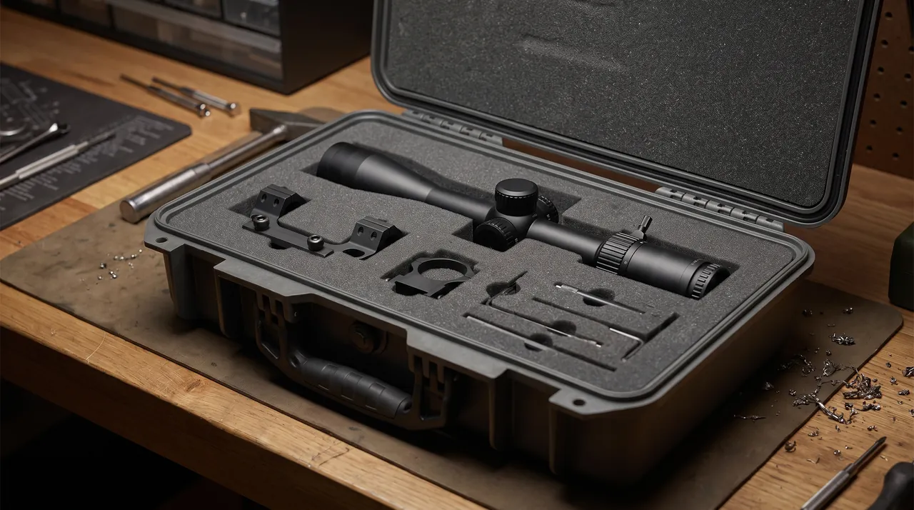
| Full profile cradle | CNC-milled EVA or PU matching the part outline | Large contact area, high locating accuracy | Precision molds, irregular structural parts |
| Layered build | Load-bearing bottom, profile middle, compression top | Balances load and protection | Mixed loads, multi-layer structural parts |
| Compartmented layout | Independent pocket per part | Prevents mutual impact, easy counting | Cross members, end plates, small structural parts |
| Adjustable dividers | Divider positions movable or removable | Low changeover cost | Mixed sizes, frequent batch changes |
For adjustable dividers in mixed multi-size scenarios, see the removable divider system, and for heavy-part handling interfaces, portable transport box structure covers forklift pockets, lifting points and stacking structures.
Two details that are easily missed.
First, the support face flatness must be inspected. This is the single biggest difference between a tray case and an ordinary toolbox. Record the measured support point heights in the inspection file as part of the shipped documentation.
Second, the insert must hold its dimensions through repeated handling. Tray parts are heavy, and every load cycle presses on the support faces, so material selection should favour types with low compression set.
9. Vibration and Transport Verification: ISTA, GB/T 4857 and ASTM D4169
A completed design is not a proven design. Tray-class parts place specific demands on testing.
Three main standard families.
- The ISTA series covers performance test procedures for transport packaging. Tray cases are heavy, large-format packaging, usually organized along the lines of ISTA 3E for unitized loads and ISTA 3B. Procedure selection is covered in the ISTA transport testing procedure.
- The GB/T 4857 series is the Chinese family of basic transport package test methods covering vibration, impact, drop, stacking and compression, and is the usual basis for domestic supply programs. See GB/T 4857 transport packaging verification.
- ASTM D4169 uses a distribution cycle framework, combining sequences by transport stage and risk level, suited to multimodal export programs. See the ASTM D4169 distribution cycle case.
Trimmed test set for a tray case.
| Test | Purpose | Key observation |
|---|---|---|
| --- | --- | --- |
| Random vibration | Simulates sustained road and rail vibration | Support migration, residual tray bow, compression loss |
| Drop and impact | Simulates handling impacts | Case cracking, base pallet distortion, part migration |
| Stacking and compression | Simulates warehouse and container stacking | Case distortion, support system compression, local tray dishing |
| Concentrated impact | Simulates forklift or foreign-object strikes | Local puncture and crush resistance |
| Temperature and humidity cycling | Simulates cross-climate and container conditions | Condensation, corrosion, insert dimensional stability, aluminium surface condition |
Three special requirements for tray-class testing.
First, measure flatness before and after the test. For a tray, good appearance with out-of-tolerance flatness is the classic hidden failure. Measure before the test, at intermediate points such as the end of each vibration segment, and after the test, producing a distortion-versus-vibration-duration curve, which is far more persuasive than a simple pass or fail statement.
Second, use real parts or stiffness-equivalent dummies. Trays are stiffness-sensitive, and substituting a rigid mass completely changes the failure mode, because a rigid mass does not flex. If a dummy is unavoidable, the report must state the relationship between its stiffness, mass and mass distribution and those of the real part.
Third, run stacking at the actual layer count and duration. Creep deformation in tray-class parts accumulates under long-term stacking and may not appear in a short test. For export programs, design the test duration around the actual stacking condition and voyage duration in the container.
On pass criteria. Define acceptance criteria in the test plan, for example a limit on flatness change after test, no visible cracks or weld damage, and no distortion of threads or hole mouths. With quantified criteria, the test result can actually be used for design confirmation.
10. Temperature, Humidity and Ocean Freight: Container Condensation
Cross-climate shipping is the biggest hidden risk in tray export programs. Aluminium parts corrode in humid environments, particularly with cutting fluid residue or dissimilar metal contact present, and sustained local loading at higher temperatures accelerates creep deformation.
Actual conditions inside a container.
- Large daily temperature swing. Under direct sun, the interior can be substantially hotter than ambient, then falls rapidly at night, producing repeated cycles.
- High relative humidity sustained over time. Interior humidity stays at high levels for extended periods, creating the conditions for condensation.
- Uncontrolled condensation location. Moisture condenses on the coolest surfaces, usually metal part surfaces or the case interior wall, exactly where the tray most needs protection.
- Long voyage duration. Ocean legs can run for weeks, and accumulated corrosion and creep time is not negligible.
A usable test method basis. MIL-STD-810H is often used as the methodological basis for environmental testing, defining procedures and tailoring methods for temperature, humidity, vibration, shock and salt fog. The correct use is to select appropriate methods and procedures, tailor them to the real transport environment and produce a program-specific profile. It must be stated clearly that MIL-STD-810H is an environmental test method standard, and using it does not mean a product has obtained any military certification. No such implication should appear in customer communication or product literature.
Four low-cost measures for tray cases.
- Desiccant plus humidity indicator card. Estimate quantity from free space and voyage duration: normally 1 to 2 kg of high-efficiency desiccant per cubic metre of free space, doubled for long ocean voyages. Place the indicator card where it is visible on opening, so it becomes quantitative acceptance evidence.
- Pressure equalization valve. A fully sealed case develops a differential as temperature changes, which shortens gasket life and makes opening difficult. A valve balances the differential while maintaining the IP rating, as explained in case pressure equalization valve.
- Aluminium surface treatment and isolation. Clean and dry thoroughly after machining, apply suitable surface protection, and add insulating separators between dissimilar metals.
- Inspect on arrival. Re-measure flatness and look for corrosion, so problems do not first appear at assembly.
On gasket and rust-preventive compatibility. The case gasket must not swell or harden because of rust-preventive or cleaner vapours; see seal material and case compatibility.
11. Lifting, Handling and Stacking Safety
Tray cases are large and heavy, so handling risk far exceeds that of ordinary packaging.
Lifting and handling points.
- The case must carry clear centre-of-gravity and lifting point markings, and lifting points must be structurally verified. Control the sling angle within a reasonable range to avoid overloading the points.
- Prefer forklift pockets. For heavy tray cases, base forklift pockets are the safest handling interface and greatly reduce sling slip and tip-over risk.
- Never lift by a protrusion. Cooling ports, fittings and lifting eyes on the tray are not lifting points, and slinging over them for convenience is the most common accident cause.
- Define and mark the permitted stack layers on both the case and the documents. State explicitly whether additional cargo may be placed on the lid.
- Constrain handling ground conditions. Forklift operation must consider floor flatness, slope and load capacity, avoiding soft ground and ramps.
- Standardize the opening sequence. Confirm the case is stable before releasing latches. Large lids should be opened with a support strut or by two people to avoid rebound or sudden drop.
On rotation and attitude control. Some trays and large structural parts are rotated during assembly. The packaging plan should state whether rotation is permitted and in which direction, and the insert should provide passages for rotation tooling. If rotation is not permitted, mark the case with a no-rotation symbol.
On re-confirming internal restraints. Compression in tray cases can relax over long distances. Including "restraints still in place and still preloaded" as an unpacking check item is worthwhile, and for long ocean voyages the plan should state whether mid-voyage re-tightening is needed.
12. Incoming Inspection, Traceability and AQL Sampling
Both the case and the packaging plan require acceptance, and acceptance covers the packed state as a whole.
Three-layer acceptance structure.
Layer one, case appearance and structure. No cracks or abnormal distortion. Hinges and latches operate freely and lock reliably. The gasket shows no gaps or compression set. Forklift pockets and base pallet are intact. Stacking location features work. Marking is legible.
Layer two, function and performance. Sealing is sampled against the declared IP rating using IEC 60529 and GB/T 4208 methods. Insert support face flatness is inspected, with support point height variation within the technical agreement limit. Insert dimensions match the drawing. Loading is smooth without jamming.
Layer three, packed state and documents. Quantities and sizes match the packing list. Support positions match the packing drawing. Compression is in place and even. Thread plugs and flange covers are fitted. Desiccant and humidity indicator card are in place. Documents are complete: case specification, insert drawing revision, flatness record, packing drawing and inspection records.
AQL sampling follows the established framework: determine sample size from batch quantity and judge by defect class. For tray cases, the following classification is practical.
| Defect class | Typical items | Judgement |
|---|---|---|
| --- | --- | --- |
| Critical | Wrong support positions, support face flatness out of tolerance, sealing failure, flange or thread damage | Not permitted |
| Major | Insufficient compression, insert migration, hinge or latch failure, signs of corrosion | Judged against limits with batch traceability |
| Minor | Cosmetic scratches, unclear marking, local insert burrs, poorly placed aids | Permitted within limits |
The full classification and sampling method is in custom case acceptance and AQL.
Marking and traceability should include at least the following.
| Marking | Suggested content | Form |
|---|---|---|
| --- | --- | --- |
| Part and tooling number | Tray model, mold number, insert revision | Durable label |
| Name and specification | Name, external dimensions, weight | Label |
| Support and packing | Support layout, packing orientation, lifting points, permitted rotation | Screen print graphic |
| Stacking limits | Permitted layers, whether top loading is allowed | Screen print graphic |
| Protection data | IP rating, desiccant replacement date | Label |
| QR code | Link to packing drawing, flatness record and inspection file | Weather-resistant label |
On one file per case. For safety-relevant tray parts, build an electronic file per case recording the support scheme, flatness data, packing photos and transfer history. When a leak or dimensional issue appears at the customer, this makes it possible to quickly determine whether the cause lies in packaging or in manufacturing.
13. Custom Insert Workflow and Selection Decision Tables
A standard workflow that can serve as a supplier technical requirement.
- Information review. Provide a 3D model in STEP or IGES or complete 2D drawings, weight and centre of gravity, stiffness distribution or rib positions, a list of critical accuracy faces, allowable deflection, lifting and handling method, and whether stacking is required.
- Concept design. Determine case size, support point count and positions, profile fit and lateral restraint, and compression method, then issue the support layout and packing orientation drawings.
- Trial fit and flatness verification. Build the first insert, measure support face flatness, and confirm support point seating and even compression.
- Adjust and freeze. Fine-tune support heights and cavity dimensions from the trial and measurement results, then freeze the drawing revision.
- Production and factory inspection. Inspect support face flatness on every unit and record it, supplying inspection documents with each case.
- Change management. When a tray or mold is revised, revise the insert drawing in step and withdraw the old revision.
For the collaboration boundary from requirement to volume production and the dimensions of supplier evaluation, including mold capability, insert machining accuracy, inspection equipment and document completeness, see how to choose a case OEM factory. JUNZHJIA provides an integrated service from 3D model interpretation and support scheme design through volume supply and OEM or ODM branding, with support face flatness records and structural parameter documents available on request. For the comparison of front-end investment and lifecycle cost, the custom case mold cost analysis offers a usable calculation approach.
Selection decision table.
| Situation | Recommended shell | Recommended insert | Priority verification |
|---|---|---|---|
| --- | --- | --- | --- |
| Short in-plant transfers | IP54 to IP65 transfer case | Multi-point support frame with pads | Support seating, handling efficiency |
| Domestic volume supply by road | IP65 heavy-duty case with forklift pockets | Multi-point support, lateral restraint, flexible compression | Random vibration, flatness re-measurement |
| Long distance and multimodal | IP65 to IP67 sealed case | Multi-point support with rigid frame | Random vibration, stacking, temperature and humidity cycling |
| Ocean export across climate zones | IP67 with pressure equalization valve | Multi-point support, desiccant, corrosion isolation | Temperature and humidity cycling, stacking, salt fog |
| Large die-casting tray molds | Steel base with plastic hood | Full profile cradle on rigid frame | Drop, concentrated impact, cavity inspection |
| Extrusion and stamping dies | IP65 standard case | Profile cradle with bearing and edge covers | Random vibration, bearing and edge inspection |
| Mixed structural components in many sizes | IP65 standard case | Adjustable dividers with compartment location | Mis-load risk, counting convenience |
Common misconceptions.
- Misconception one: a tray is stiff, so a few pads will do. A tray is exactly the large thin-wall part with the least stiffness, and support layout is the core issue.
- Misconception two: good appearance means no damage. Tray damage is mainly residual bow and must be measured.
- Misconception three: rigid clamping is the safest. Rigid clamping introduces restraint stress, and the part may spring back on release.
- Misconception four: softer support faces are safer. Too soft makes support heights inconsistent and worsens distortion.
- Misconception five: IP67 means long-term submersion. The definition is temporary immersion and cannot be extrapolated.
- Misconception six: one test result stays valid. Part revisions, route changes and case ageing all invalidate it.
Frequently Asked Questions
Q: What is the most typical damage in battery tray transport, and why is it more dangerous than impact damage? A: The most typical damage is residual bow, meaning a tray arrives with an unrecoverable flatness deviation. Its danger comes from three properties. The first is concealment: the tray often looks completely normal and only a measurement reveals the problem, so it flows into assembly easily. The second is amplification: a form deviation at the 0.3 mm level becomes several functional problems at once, including uneven thermal pad compression because the module mounting face is not flat, a failed leak test because the flange does not seat, and reduced fatigue life because stress concentrates at the body attachment points. One small deviation turns into multiple functional issues. The third is attribution difficulty: because it was not detected on arrival, the problem typically appears at end-of-line pack test or vehicle road test, by which point it is hard to separate manufacturing deviation, transport distortion and assembly stress, and responsibility becomes unclear. Prevention rests on three actions: place enough support points at consistent heights according to the stiffness distribution, avoid rigid clamping that introduces restraint stress, and add flatness re-measurement to the unpacking checklist so the problem is intercepted before production.
Q: How should support points for a tray be laid out, and how many are enough? A: Support layout follows four principles. First, use enough points: for trays longer than 1.2 metres allow no fewer than four, and above 1.8 metres six or more, since wide spacing lets mid-span deflection exceed flatness tolerance. Second, place points at high-stiffness features, preferring longitudinal members, reinforcing ribs, side members or structural corners, because these have high local stiffness and restrict distortion; placing support under a thin flat panel causes local dishing. Third, keep heights identical, which is the most easily missed point, since a 1 mm height difference is equivalent to imposing an initial bend, so insert support faces must be inspected for flatness and recorded. Fourth, choose contact face hardness in the right range, because a face that is too soft lets the tray sink and makes the effective heights inconsistent, while a face that is too hard concentrates stress; a high-density load-bearing frame with a medium-density contact pad is the common engineering solution. The final count should follow tray length, stiffness distribution and allowable deflection, and a simple beam model or finite element estimate at the concept stage gives a rational basis for choosing the points.
Q: If trays must be stacked for transport, how should that be handled? A: Stacking is not absolutely prohibited, but three problems must be solved. The first is the load path: the upper tray must not transfer load through the lower tray's sealing face, formed surface or thin wall, so dedicated interlayer spacers are required and load must pass through structural features such as longitudinal members, ribs and corner posts. The second is stiffness matching: stacking trays of very different stiffness makes the less stiff one take additional deformation, so mixed stacking should be avoided, and if it is unavoidable the less stiff tray should go on top with fewer layers above it. The third is stability and stack height: stacking raises the centre of gravity and reduces tip-over resistance, so lashing and restraint must be verified and the permitted layer count must be marked on both the case and the documents. Long-term stacking also causes creep deformation, which is more pronounced inside a warm container, so the combination of layer count and stacking duration needs separate evaluation. Where possible, the more robust approach is a dedicated rack or case with interlayer support features, turning stacking into structured stacking.
Q: What special packaging requirements apply to aluminium trays? A: Aluminium brings three specific requirements. First, low surface hardness makes it easy to scratch: aluminium is much softer than steel and is readily scored or dented by hard objects, especially on machined sealing and mounting faces, so insert contact areas must avoid hard sharp edges and rough surfaces, and aluminium parts must never be pressed together and then allowed relative motion. Second, the anodic oxide layer is relatively brittle: the film is hard but brittle, and concentrated local loading produces micro-cracks or spalling, which then becomes a corrosion initiation site, so support and compression points should avoid edge regions of anodized faces and spread contact stress. Third, there is galvanic corrosion risk: aluminium in direct contact with copper, stainless steel or carbon steel forms a galvanic couple in humid conditions and corrodes preferentially as the anode, so steel fasteners, steel label clips and steel frames must not touch aluminium directly, and particular care is needed when aluminium shares a case with copper busbars. Cutting fluid residue after machining, especially chloride-bearing fluid, is a major corrosion trigger, so parts must be cleaned and fully dried before packing, and an insulating separator such as PE film or non-woven fabric should be placed between dissimilar metals while keeping the case interior dry.
Q: What transport testing does a battery tray case need, and how should pass criteria be set? A: The usual method basis is the ISTA series, the GB/T 4857 series and ASTM D4169, covering random vibration, drop and impact, stacking and compression, concentrated impact, and temperature and humidity cycling. Tray-class parts add three special requirements. First, flatness must be measured before and after testing, because the classic hidden failure of a tray is good appearance with out-of-tolerance flatness; measure before the test, at intermediate points such as the end of each vibration segment, and after the test, producing a distortion-versus-duration curve, which is far more valuable than a simple pass or fail result. Second, the test item should be a real part or a stiffness-equivalent dummy, because trays are stiffness-sensitive and a rigid mass changes the failure mode entirely since it does not flex; if a dummy is used, the report must state the relationship between its stiffness, mass and mass distribution and those of the real part. Third, stacking should run at the actual layer count and duration, because creep accumulates under long-term stacking and a short test may not reveal it. Pass criteria should be quantified in the test plan, for example a limit on flatness change, no visible cracks or weld damage, and no distortion of threads or hole mouths, so that the result can be used for design confirmation.
Q: How should IP65 and IP67 be chosen, and why does an ocean freight program also need a pressure equalization valve? A: IP65 means dust tight and resistant to water jets, while IP67 means dust tight and able to withstand temporary immersion, typically 1 metre for 30 minutes. Match the rating to the situation: for in-plant transfers and dry environments, IP54 to IP65 is sufficient; for domestic road supply, IP65 usually offers the best value; for ocean export, humid and rainy regions, long-term storage and yards exposed to standing water, IP67 is recommended. Remember that an IP rating describes only resistance to solid foreign objects and water, not load capacity or impact resistance. A pressure equalization valve is necessary because of physics: in a fully sealed case, temperature changes alter the internal gas volume and create a differential across the shell, with three consequences. The gasket is repeatedly compressed or deformed, leading to long-term sealing failure. The case becomes hard to open, so crews may pry with tools and damage latches. In extreme cases the gasket is forced open and the interior exchanges air with the humid outside. A valve lets gas pass slowly once the differential exceeds a threshold while a hydrophobic membrane maintains the IP rating, which is why in cross-climate shipping it is often more effective than simply raising the IP class.
Q: Where does the difficulty lie in accepting a tray packaging case? A: The difficulty is that the packed state as a whole is harder to accept than the case itself. Case appearance, hinges, latches and gaskets all have mature acceptance methods, but three hidden indicators decide whether tray packaging works. First, whether the support positions match the packing drawing, because once the shop floor adjusts support positions by judgement, the designed deflection control is lost. Second, whether support face flatness meets the requirement, because support height variation translates directly into an initial bend of the tray, so it must be measured and recorded for every unit, and this is the core inspection item that separates a tray case from an ordinary toolbox. Third, whether compression is both sufficient and not excessive, since insufficient compression allows movement in transit and excessive compression introduces restraint stress. A three-layer acceptance structure therefore works best: case appearance and structure; function and performance including support face flatness and sealing; and packed state and documents including support positions, compression, protective fittings, desiccant and accompanying documents. Sampling frequency and limits should be agreed within an AQL framework, with wrong support positions, support face flatness out of tolerance, sealing failure and flange or thread damage classed as critical defects that are never permitted.
Q: What is the workflow for a custom battery tray case insert, and what information is required? A: The standard workflow has six steps: information review, concept design, trial fit with flatness verification, adjustment and freeze, volume production with factory inspection, and change management. The core information includes a 3D model of the part in STEP or IGES format, which is easiest for reading the outline, or complete 2D drawings; weight and centre of gravity; stiffness distribution information such as the position and direction of longitudinal members and reinforcing ribs, which is the key input for support point decisions; a list of critical accuracy faces including sealing flanges, mounting faces and datum faces; allowable deflection or flatness acceptance limits; the lifting and handling method, whether by sling, forklift or rotation tooling, and whether rotation is permitted; whether stacking is required and the permitted layer count; and the intended transport mode and distance, including whether ocean freight is involved. The more complete the input, the higher the chance the concept passes first time. The trial fit and flatness verification step is the most critical, because it exposes problems invisible at the design stage, such as support points landing on insufficiently stiff regions, uneven compression distribution, or inadequate relief for a fitting. Once the trial and measurements pass, freeze the drawing and move to volume production; if the tray or mold is later revised, the insert drawing must be revised in step and the old revision withdrawn.
Conclusion & Related Reading
Packaging EV battery trays and structural components is fundamentally a structural distortion control problem, not a loading and securing problem. Four statements summarize the article. First, the vulnerable points are flatness, weld joints, sealing faces, mounting holes and cooling ports, and flatness failure is the most concealed and most consequential, so it must be accepted by measurement rather than visual judgement. Second, support point design is the core of the packaging design: enough points, positions at high-stiffness features, strictly identical heights and contact faces of appropriate hardness, while avoiding rigid clamping that introduces restraint stress. Third, shell sealing is matched to the situation, starting at IP65 and moving to IP67 with a pressure equalization valve for ocean export, together with desiccant and a humidity indicator card to control condensation. Fourth, tray molds are protected to precision tooling standards: weight carried at the mold feet, zero load on parting faces and cavities, and relief for every protrusion.
Written down, these actions become an executable packaging plan: case specification and IP rating, support layout drawing and flatness records, profile fit and lateral restraint, compression method and points, corrosion protection configuration, desiccant quantity, verification test items with quantified criteria, marking and traceability content, and the unpacking checklist including flatness re-measurement. JUNZHJIA can provide multi-point support insert customization based on the actual tray and mold outlines, heavy-duty case OEM and ODM supply, and support face flatness records and structural parameter documents, helping new energy supply chain organizations turn packaging into a controlled process.
Related Reading