


In burner and combustion-equipment spare-parts logistics, the leading cause of failure for nozzles and valve trains is not impact damage but contamination, moisture and movement. Atomising holes become blocked by metal chips or fibres, valve spools seize because of corrosion from moisture, and pre-set regulating springs drift under prolonged vibration. The design direction for a burner parts case should therefore be cleanliness control, precision location and moisture plus static protection, not simply a thicker cushioning layer. The conclusion: nozzles and valve trains should travel as one item per cavity, in clean packaging, individually sealed and traceably identified, with performance verified against the GB/T 4857 and ISTA test series. JUNZHJIA supplies this class of case with custom inserts, OEM/ODM programmes and volume production to burner manufacturers, boiler suppliers and combustion-equipment traders.
A second characteristic of this component family is that it is numerous, dense in value and non-substitutable. The valve train of an industrial burner may contain a dozen solenoid valves and fittings of near-identical appearance, and there may be three to five nozzle spare sets with different flow ratings. Shipped loose, it is extremely difficult on site to tell which item belongs to which position. Fit the wrong one and unstable combustion at commissioning is misdiagnosed as a control-system problem, making fault-finding very expensive. This article gives cleanliness grades, insert solutions, sealing strategy and an acceptance method by component category, with comparison tables and a FAQ section for burner engineers and procurement staff.
Table of Contents
- 1. Nozzles and Valve Trains: Why Cleanliness Matters More Than Impact Resistance
- 2. Component Categories and Cleanliness Grades
- 3. Nozzle Cases: Atomising Nozzles, Lances and Swirlers
- 4. Valve Train Cases: Solenoid, Regulating and Ball Valves
- 5. Filters and Flow Meters
- 6. Ignition Electrodes and Flame Detectors
- 7. Servo Actuators and Linkage Mechanisms
- 8. Cleanliness Control: The Process Chain from Cleaning to Packing
- 9. Static Control and Protection of Electrical Components
- 10. Cleanliness-Grade Insert Materials Compared
- 11. Sealing, IP Ratings and Desiccant Strategy
- 12. Test References and Traceability
- 13. Arrival Inspection and AQL Sampling
1. Nozzles and Valve Trains: Why Cleanliness Matters More Than Impact Resistance
Start with an engineering fact: atomisation quality is determined by orifice diameter, orifice roundness and internal passage roughness, and all three are extremely sensitive to contamination. Pressure-atomising nozzles used on industrial burners commonly have orifices of 0.3 to 2.0 mm, and the gas ports of twin-fluid nozzles are smaller still. A single metal chip, a fibre, or a flake of cured sealant is enough to cause off-axis flow, an abnormal spray cone angle or a flow deviation. None of this is visible at assembly; it only appears at ignition and commissioning.
Valve trains concentrate their problems at the moving interfaces. Between a solenoid spool and its guide sleeve, between a regulating valve disc and its seat, and between a ball and its seat ring, the fits are tight. If dust enters in transit, the result ranges from increased actuation resistance to seizure. If moisture enters and remains, the result is corrosion and pitting, especially on metal sealing faces.
The third problem is state drift. Regulating valves and flow-control valves are often set and marked at the factory. Prolonged random vibration changes spring preload and shifts the set value. Such drift leaves no external trace but directly affects combustion conditions.
The evaluation criteria for a nozzle and valve-train case should therefore be cleanliness retention, displacement control, humidity control and state traceability. Cushioning is of course required, but it is not the main contradiction. A thicker foam layer does not solve contamination; it may even introduce a new risk through debris shedding.
2. Component Categories and Cleanliness Grades
Grading by cleanliness requirement, moving-interface precision, electrical characteristics and weight is more meaningful than grading by weight alone.
| Protection grade | Typical components | Dominant failure mode | Cleanliness requirement | Insert and packaging strategy |
|---|---|---|---|---|
| --- | --- | --- | --- | --- |
| N1 High-cleanliness precision | Atomising nozzles, swirlers, lance tips, fine filter elements | Blockage, scratching, deformation | Highest; no debris, no silicone | One bag per item plus contoured cavity plus cap or plug |
| N2 Precision moving interface | Solenoid valves, regulating valves, ball valves, proportional valves | Seizure, corrosion, set-value drift | High; no dust | One cavity per item plus soft location plus lead seal |
| N3 Electrically sensitive | Ignition transformers, flame detectors, controller modules, servo drives | ESD damage, moisture, broken leads | Medium to high; anti-static needed | Anti-static bag plus anti-static insert plus fixed leads |
| N4 Structural | Lance tubes, connecting flanges, brackets, short pipe spools | Bending, coating damage | Moderate | Half-round cradle plus hard stops |
After grading, one important operating rule is that items of different cleanliness grades must not share a cavity. Mixing N1 with N4 is a common error: machining residue, coating flakes and packaging debris from a structural part will contaminate an N1 component. The correct approach is to give N1 its own case or its own cavities and to complete cleaning before packing.
For N1 components, one item per cavity is the baseline, and dual isolation of bag plus cavity is recommended: first seal each item in a clean, silicone-free, low-outgassing bag, then place it in a contoured EVA cavity. Cavity depth should be 1/2 to 2/3 of component height so nothing escapes when the case is inverted. Expel most of the air from the bag before packing to prevent the bag from rubbing back and forth in transit.
3. Nozzle Cases: Atomising Nozzles, Lances and Swirlers
The nozzle is the classic small, expensive item. Its relationship with a parts case splits into three groups: the nozzle tip body, the lance tube including its assembly, and the swirler and distribution disc.
The nozzle body is N1 grade. Protection points:
- The orifice must not contact any hard surface; leave a 5 to 10 mm void in the cavity at the orifice end.
- Fit a soft cap at the orifice end, either a silicone cap or a purpose-made plug, and the cap material must be silicone-free or low-outgassing so it cannot contaminate the passage.
- Bag each nozzle body individually; for a needle-valve or spill-return nozzle, keep the needle in an unloaded position and never bottom it out.
- Never wrap the orifice end directly in foam, because open-cell foam can retain foam crumbs.
The lance tube is N4 grade but carries an N1 end. A lance is a slender tube that bends easily in transit while its tip connection is high precision. Use end-focused protection plus multiple mid-point supports: soft sleeves or purpose-made caps at both ends and two half-round cradles at mid-length, evenly distributed. Straightness can be spot-checked at acceptance with a taut line.
Swirlers and distribution discs are thin-walled perforated parts whose main risks are compressive deformation and impact damage to the hole edges. The cavity should restrain the outer diameter and the end face together; the hole field must never carry load. Where several similar items travel together they must be separated by soft dividers to prevent mutual rubbing.
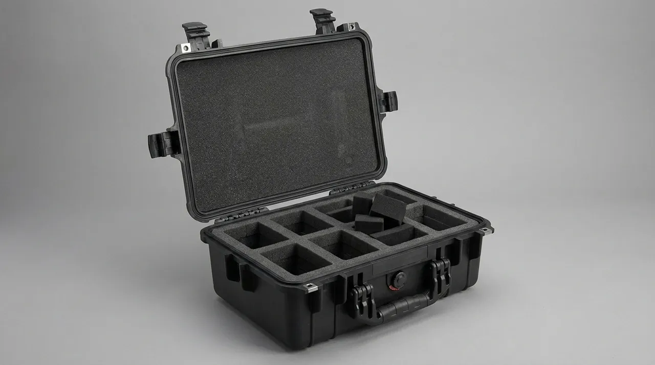
For nozzle spare sets of the same model at different flow ratings, compartmentalise by flow rating inside one case and label each compartment with rating and application. This has high on-site value: at commissioning the correct item can be taken directly from its compartment without measuring every piece. Where a load must be shipped as one case and picked compartment by compartment, use a removable divider system (removable divider system design).
For nozzles that have been flow-calibrated, attach a calibration label to each item and seal it; check the label before opening the seal at site. Include a humidity indicator card in the case so that moisture exposure can be judged.
4. Valve Train Cases: Solenoid, Regulating and Ball Valves
The valve train is the most standardised part of a burner spare-parts set and the part most often compromised by loose management.
Solenoid valves depend on the clearance between spool and guide sleeve and on spring force. Protection points:
- One cavity per item; bodies must not touch neighbouring items and must never be clamped by steel straps or rigid bars.
- Coil leads should be coiled and secured with a soft tie, never pulled in tension; where extra lead length exists, secure it in a dedicated channel.
- Fit plugs to the inlet and outlet ports to keep dust out of the passage.
- Keep the body orientation stable so the spool is not loaded sideways over long periods.
Regulating and proportional valves carry a set state and are state-sensitive items. Fit a lead seal or binding wire before packing and mark the case exterior as set-and-sealed; verify the seal before opening on arrival. Diaphragms and springs are temperature sensitive, so avoid prolonged high-temperature exposure.
Ball valve assemblies are relatively heavy but their ball-to-seat fit is precise. Stand them upright or lean them at an angle so the ball is not loaded on one side over time. Remove or secure the handle so that force cannot rotate the valve in transit.
For set integrity management of a valve train, group by circuit: the train for one combustion circuit, including solenoid, regulating valve, ball valve and fittings, is stored and identified as one group with a circuit number. This lets site teams assemble and commission circuit by circuit, avoiding wiring and piping errors caused by mixing. Compartment inserts can use colour-coded strips to distinguish circuits for fast identification.
For valve trains with electrical connectors, fit dust caps to the connectors. Where connector shells are metallic, isolate them from stainless parts to prevent galvanic corrosion.
5. Filters and Flow Meters
Filters and filter elements are N1 grade. The filter medium deforms under compression, folds and contaminates, and once crushed the filtration rating cannot be restored. Use a dedicated cylindrical cavity matched to element outer diameter, slightly deeper than element length, with soft end pads; no side loading is permitted. Bag each element individually so it cannot touch other items.
For metal screens, including sintered and woven types, bending is prohibited. The cavity must ensure the screen cannot touch a hard surface in any orientation.
Flow meters may be positive displacement, turbine or differential pressure types. Their common feature is internal moving parts or sensing elements, plus factory calibration. Protection points: one cavity per item, no inversion for designs where this matters, plugs on inlet and outlet, and avoidance of strong vibration. For calibrated meters, fit tamper-evident identification and verify at unpacking.
Combined filter-and-meter units are larger, so a split insert is recommended to allow staged removal on site.
For gas systems that require clean installation, the packing area for filters and valve trains must be separated from machining areas. This often matters more than the case itself: if the air in the packing area carries suspended metal dust, even a perfectly sealed case will be contaminated at the moment of packing.
6. Ignition Electrodes and Flame Detectors
Ignition electrodes are ceramic insulators, combining brittleness with precision. The ceramic body fears impact, local compression and thermal shock. Protection points:
- One cavity per item, matched to the ceramic outline, with soft padding at the contact face.
- The electrode rod is slender metal; leave voids at both ends so that the ceramic body never carries the rod bending moment in transit.
- Never squeeze the ceramic surface with foam; locate and support rather than clamp.
- The spark gap is set at the factory and must not shift in transit.
Flame detectors, whether ultraviolet, visible-light or ionisation type, contain an optical window and a photoelectric element. The window scratches and oils easily; the element is sensitive to static and moisture. Protection points: a removable transparent window cap, one anti-static bag per item, and anti-static insert material. For ionisation probes, fit a protective sleeve over the probe.
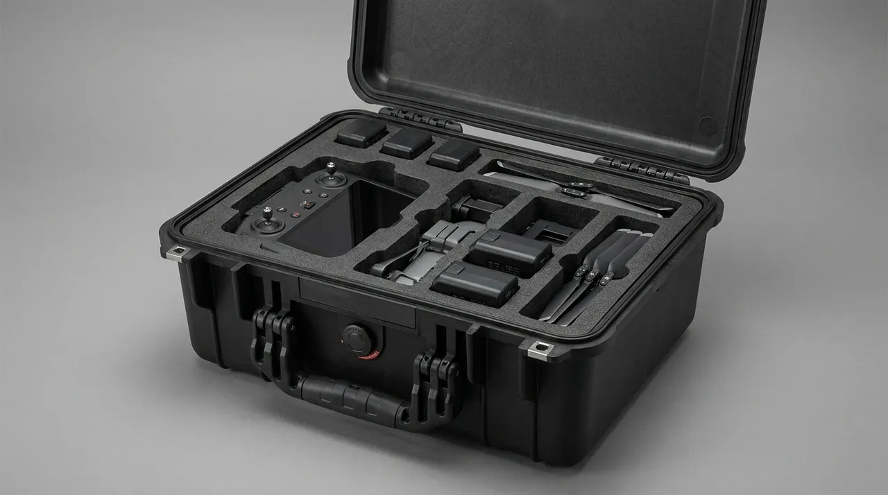
Controller modules and control boards are N3 grade. Their main risks are electrostatic discharge damage, moisture and broken leads. Use sealed anti-static bags, anti-static and flame-retardant insert material, and never let boards touch ordinary foam directly, since ordinary foam can carry static. Fit dust caps to terminals. Where components are especially static-sensitive, use a full anti-static insert solution (anti-static and flame-retardant insert solution).
Sealing level matters equally for these electrical components. For spares stored long-term in humid conditions, aim for IP65 or better with desiccant; for ocean freight, IP67. For the difference between levels and how they are verified, see waterproof cases and IP ratings.
7. Servo Actuators and Linkage Mechanisms
A servo actuator is the electromechanical element of a burner, typically comprising servo motor, gearbox, output shaft and linkage. It has three failure modes: bearing damage from side load on the output shaft, changed grease performance at temperature extremes, and shift of the set travel position.
Protection points:
- Zero side load on the output shaft is a hard requirement. The cavity must restrain the motor body and gearbox so the shaft is free; never use the shaft as a support point.
- If the shaft must be restrained, use a soft bushing matched to shaft diameter and do not compress it.
- For actuators whose travel has been set, record the travel value, mark it, and verify at unpacking.
- The linkage is a slender part; remove it and pack it separately rather than shipping it as a load path on the actuator.
- For actuators with encoders or potentiometers, avoid strong impact, because encoder discs are fragile.
On temperature, the grease and electronics inside a servo actuator have limits. On multi-climate routes the case interior can reach high temperatures; inside a container in direct sun, temperatures above 60 C are possible. Choose temperature-resistant insert materials and avoid materials that soften at high temperature. For related material and structural considerations see wide-temperature-range case solutions.
8. Cleanliness Control: The Process Chain from Cleaning to Packing
Cleanliness is not a matter of paying attention at packing time; it is a process chain. Establish a work instruction along these steps:
- Clean: purge or wash components before packing to remove machining residue, cutting fluid and grease. For nozzle passages, use clean compressed air or nitrogen.
- Dry: components must be fully dried after cleaning; residual liquid inside a sealed case becomes a corrosion initiation site.
- Inspect: examine passages and orifices with a borescope or magnifier and confirm no residue remains.
- Cap: fit plugs or caps to all ports, orifices and tube ends. Plug material must be silicone-free or low-outgassing.
- Bag: bag N1 components individually in clean bags and expel the air.
- Load: place into a clean insert whose cavities have been cleaned and checked for debris.
- Record: record the packing list, component numbers, cleanliness inspection result, packing date and operator.
Packing-area management is equally critical: keep it away from cutting, grinding and blasting stations; keep floors and benches easy to clean; require lint-free gloves and prohibit ordinary cotton gloves, which shed fibres.
Insert material choice directly determines whether cleanliness can be retained. Wood, felt, open-cell foam and pearl foam are unsuitable for direct contact with N1 components; closed-cell EVA or PE is recommended, optionally with a clean barrier film. For a detailed comparison see case foam material comparison.
The case itself must also be clean. Clean the interior walls, latches and gasket grooves before each use; when returning a case to service after long storage, check the gasket for ageing and the groove for accumulated dust. For cleaning methods see how to clean and maintain a protective case.
9. Static Control and Protection of Electrical Components
Among burner spares, ignition transformers, flame detectors, controllers and servo drives are static-sensitive devices. ESD damage is insidious because it does not always cause immediate failure; it shortens life or causes parameter drift, so it is easily overlooked.
Static control has three layers.
The first is anti-static packaging material. Use anti-static shielding bags, metallised type where appropriate, rather than ordinary plastic bags, which generate and retain static. For boards, use a shielding bag plus anti-static bubble wrap.
The second is anti-static case and insert. Insert material with a surface resistance in the 10^6 to 10^9 ohm range can bleed static slowly without causing a fast discharge that damages the device. Where the project requires it, use anti-static and flame-retardant inserts (see anti-static and flame-retardant insert solution).
The third is control of handling and transport. Operators wear anti-static wrist straps; packing-area floors are treated for static dissipation; and the case is not rubbed hard against synthetic textiles in transit. For multi-layer stacked shipments, friction between cases also deserves attention.
Note that anti-static and flame retardant are different properties. UL94 is a widely used standard for evaluating the burning behaviour of plastic materials, for example UL94 V-0. For transport packaging, where the project is in a location with explicit fire requirements or involves air freight, the insert material can be required to provide UL94 flame-retardant evidence. This should be agreed in the technical agreement in advance rather than tested afterwards.
10. Cleanliness-Grade Insert Materials Compared
The table below gives insert and packaging material guidance for burner and nozzle spares.
| Material or form | Cleanliness | Cushioning and support | Anti-static | Suitable components | Cautions |
|---|---|---|---|---|---|
| --- | --- | --- | --- | --- | --- |
| Closed-cell precision-milled EVA | High | Good support, moderate cushioning | Available in anti-static grade | N1 nozzles, N2 valve trains | Needs desiccant in humid conditions |
| Anti-static flame-retardant EVA or PE | High | Good support | Excellent | N3 control modules, detectors | Requires UL94 evidence |
| Nitrile or CR foam | Medium to high | Excellent cushioning | Fair | Oily parts, filter housings | Higher cost |
| Self-skinning PU foam | Moderate | Excellent conformity | Fair | Irregular valve bodies, saddles | Control density consistency |
| PE pearl foam | Low, sheds debris | Fair cushioning | Fair | N4 void fill and gap packing | Keep away from nozzles and passages |
| Felt or non-woven | Low, sheds fibres | Weak support | Fair | Surface barrier (N4 only) | Do not use for N1 or N3 |
| Anti-static shielding bag | High as packaging | None | Excellent | Boards, detectors, transformers | Seal and expel air |
| Clean silicone-free soft bag | High | None | Fair | N1 nozzle single-item packaging | Material must be silicone-free and low-outgassing |
Follow the principle of choosing material by cleanliness grade and cavity form by stiffness: first determine the cleanliness grade and exclude debris-shedding, moisture-retaining and silicone-bearing materials, then set the cavity structure and support method by stiffness and weight. For N1 and N3 components it is better to spend more on material than to accept contamination and static risk.
11. Sealing, IP Ratings and Desiccant Strategy
Case protection levels are defined by IEC 60529, and the identical Chinese standard is GB/T 4208. Burner spares cases typically involve two levels.
| Rating | Meaning | Typical scenario | Configuration |
|---|---|---|---|
| --- | --- | --- | --- |
| IP65 | Dust tight, protected against water jets | In-plant movement, indoor storage | Silicone gasket plus desiccant |
| IP67 | Dust tight, protected against temporary immersion | Ocean freight, open yards, rainy-season long haul | Reinforced seal plus pressure equalisation valve plus desiccant |
One misconception deserves attention: better sealing does not mean a drier interior. If the air sealed inside a case has high humidity, that moisture is locked in, and when the temperature falls the vapour condenses on cold surfaces, usually metal components. A sealed case therefore must have desiccant, plus a humidity indicator card to show its state.
Desiccant quantity is determined by free volume, sealing level, transit duration and destination climate. A practical value is 20 to 50 g of silica gel per 20 L of free volume, taking the upper end for ocean freight or humid destinations. For cases opened repeatedly, provide a quickly replaceable desiccant compartment.
A pressure equalisation valve is especially valuable on multi-climate routes: when a case undergoes sharp temperature change, the differential pressure can force the gasket into the case or bulge the shell; the valve allows gas to exchange slowly and equalise the pressure while blocking liquid water and dust. For principles and selection see pressure equalisation valve configuration.
Latches and hinges are the critical interfaces for maintaining a seal. For cases opened frequently, choose a design with replaceable gaskets so that an aged gasket does not scrap the whole case. See toolbox hinge and latch sealing structure.
12. Test References and Traceability
Verification of a burner spares case should rest on two kinds of evidence: transport packaging test evidence and evidence of the component state itself.
For transport packaging testing, three families are common: the GB/T 4857 series (vibration, impact, stacking, drop methods), the ISTA series (test sequences organised around the distribution environment), and ASTM D4169 (distribution cycle plus assurance level). For small, high-value cargo such as nozzles and valve trains, complete at least vibration, impact and stacking, and add a post-test cleanliness re-check: open the case and inspect for newly generated debris in the cavities and confirm that plugs remain intact. For methods see GB/T 4857 transport packaging testing and ISTA transport testing procedures.
Where an environmental test reference is required, MIL-STD-810H may be used as a reference for environmental test methods such as temperature and humidity, vibration, shock and salt fog. It is not a military certification and does not constitute product certification, and external documents must state this precisely to avoid any misreading as military grade. See MIL-STD-810H test reference notes.
For component state traceability, supply with the case: a packing list with component numbers and quantities, a cleanliness inspection record, lead-seal numbers for set-and-sealed items, a record of the initial humidity indicator card state, and test reports where applicable. For export projects involving gas or explosion-protected applications, the documents should show awareness of standards for electrical equipment in explosive atmospheres, such as the IEC 60079 series and the GB/T 3836 series. This must be stated precisely: those standards address the explosion protection performance and certification of the equipment itself and have nothing to do with the packaging case; the case cannot substitute for the equipment certification. The case's responsibility is to prevent mechanical and environmental contamination in transit.
Export projects should also consider phytosanitary requirements for wood packaging: where the destination country requires it, a rigid case removes the fumigation step and its waiting time.
13. Arrival Inspection and AQL Sampling
Acceptance should follow a three-check, one-compare flow.
Begin at the case exterior: look for rupture or distortion of the shell and, more importantly for this cargo, any water staining or oil staining that could signal contamination of the nozzle orifices and valve-train spools. Confirm that seals and lead seals are intact and match the packing record, and read the humidity indicator card; a change means the nozzle passages and valve bodies must be checked for oil film or moisture before commissioning.
Check cleanliness: on opening, first look for debris, fibres or dust in the cavities; confirm plugs are intact and none have fallen out; for N1 components inspect passages with a borescope where necessary.
Check the state: verify component numbers and quantities; verify lead-seal numbers on set items; verify calibration labels; inspect terminals and leads for damage or signs of breakage.
Compare dimensions and clearances: spot-check the spark gap on ignition electrodes, inspect nozzle orifice end faces for impact damage under magnification, and verify recorded travel values on actuators.
For volume orders, incoming inspection of cases and inserts can follow an AQL sampling plan (see custom case acceptance and AQL sampling): appearance defects at general inspection level II with AQL 2.5; defects affecting protective performance such as missing gasket, misaligned cavity, non-conforming anti-static performance or failed latch at AQL 0.65 or under tightened inspection. For high-cleanliness projects, add a debris sampling item for inserts, using a clean tape-lift method to check for residual particles.
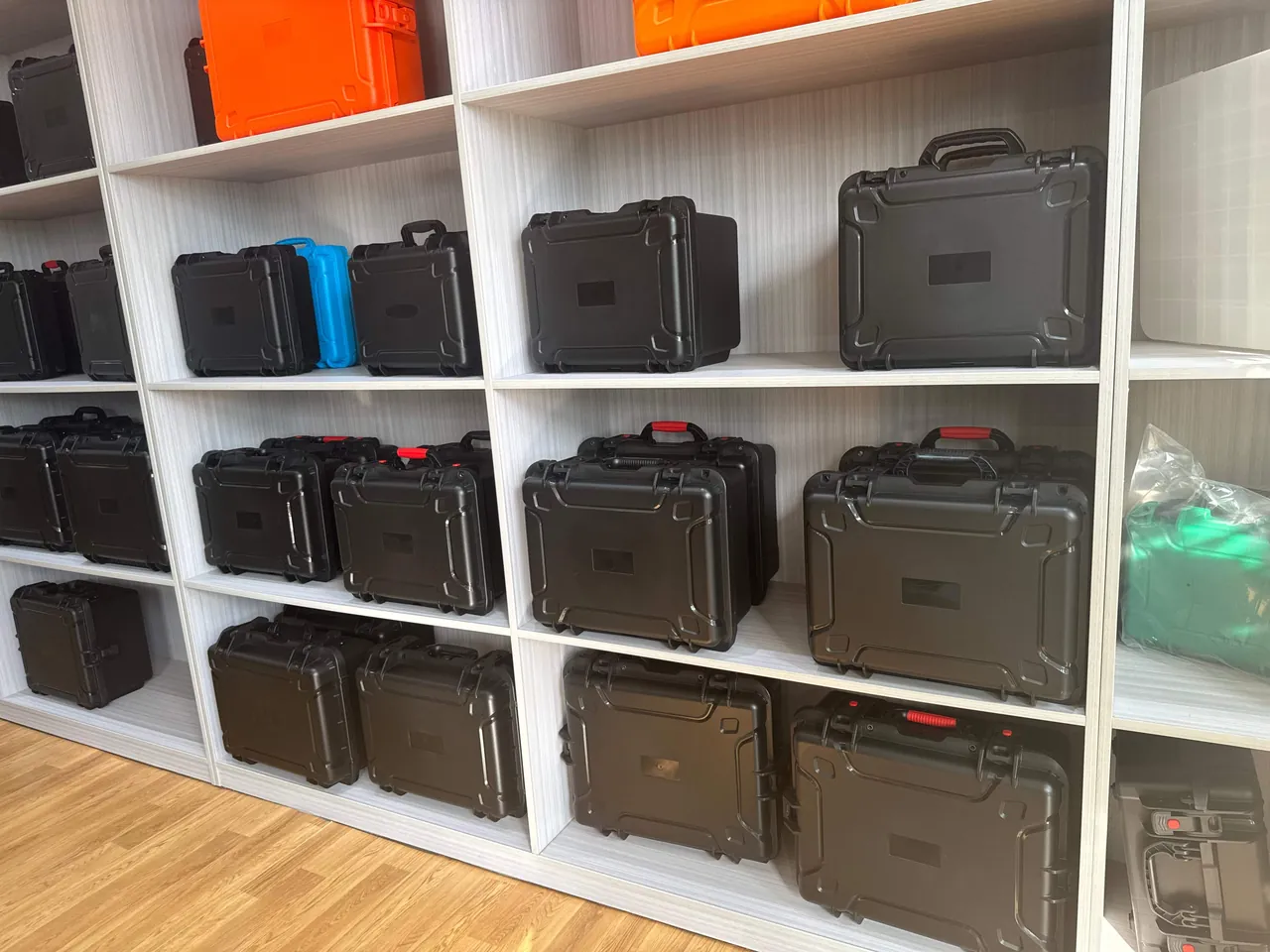
The OEM/ODM flow typically runs: requirement clarification (component list, cleanliness requirements, electrical characteristics, sensitivity, transport mode and destination), grading and compartment plan, insert design plus clean packaging concept, sample case trial fit with cleanliness confirmation, test verification, volume production, and delivery with identification. At sample stage it is worth confirming specifically whether the loading and unloading action itself generates debris, because that determines whether cleanliness can be retained long term. JUNZHJIA supports the sample stage with insert drawings, clean-packing work guidance and trial-fit feedback, supplies seals and hardware configured to each nozzle family, and returns trial-fit records plus clean-packing documents with debris-sampling results.
For cases intended for reuse across projects, use a standard shell plus changeable insert strategy: the shell and hardware are common while inserts are component-specific, which is especially economical for burner manufacturers with frequent repeat projects. Where tooling is involved, evaluate mould amortisation first (see protective case mould cost analysis). When selecting a supplier, also confirm the source and consistency of anti-static materials so that protective performance does not vary between batches (see identifying genuine versus counterfeit protective cases).
FAQ
Q: What damage do nozzles most commonly suffer in transit, and why is foam wrapping alone not enough?
A: The most common damage is not fracture but blockage and slight deformation: the orifice blocked by metal chips, fibres or flakes of cured sealant, the orifice edge burred by impact, or the needle valve bottomed out so that its mating face is damaged. None of this is visible at assembly and it only appears at ignition and commissioning as off-axis flow, an abnormal spray cone angle or a flow deviation, which is expensive to diagnose. Foam wrapping alone fails for two reasons. First, ordinary open-cell foam and pearl foam shed debris under vibration, and that debris goes straight into the very orifice that must be kept clean, effectively protecting a precision item with a contamination source. Second, wrapping merely buries the item in material without locating it, so it can still move and rub inside the packaging. The correct approach is a clean single-item bag plus a contoured EVA cavity for location, with a void at the orifice end and a soft cap, and a cavity depth of 1/2 to 2/3 of component height so that displacement is limited without any pressure on the orifice end.
Q: Why does a valve train need set integrity and circuit grouping?
A: Because the risk with a valve train is not only damage to individual items but also wrong fitting and loss. The valve train of an industrial burner often contains a dozen solenoid valves, regulating valves, ball valves and fittings of similar appearance, several of which look nearly identical and differ only in the tag or the port size. Shipped loose, the site team must verify each item individually, and one wrong position leads at commissioning to unstable combustion, ignition failure or abnormal load response. Those symptoms are easily misdiagnosed as control-system or fuel problems, lengthening fault-finding considerably. Grouping by circuit, storing the train for one circuit as a unit labelled with its circuit number, has two benefits: the site team can assemble and commission circuit by circuit, reducing mixing errors, and missing items are discovered immediately rather than halfway through assembly when work stops. Combined with compartment inserts and colour-coded strips, identification becomes much faster, which is valuable on projects with tight maintenance windows.
Q: What do IP65 and IP67 mean for burner spares?
A: IP65 is dust tight and protected against water jets, suitable for in-plant movement, indoor storage and covered road transport. IP67 is dust tight and protected against temporary immersion, typically 1 m for 30 minutes, suitable for ocean freight, open yards and rainy-season long-haul transport. For burner spares the key is not waterproofing but dust exclusion. What nozzles and valve trains fear most is dust contamination, so whichever level is chosen, the first objective is complete dust tightness, which is the first digit, 6. The difference between the two lies in liquid water scenarios: choose IP67 if the case may contact standing water or prolonged rain, and IP65 is sufficient and more economical for indoor circulation. Two cautions apply. First, the achieved level depends on gasket compression and condition, normally 20 to 30 percent compression, and gaskets need periodic inspection and replacement. Second, a sealed case must have desiccant and a humidity indicator card, otherwise the moisture present at sealing is locked inside and condenses on metal components when the temperature falls.
Q: How can you tell whether an insert material will cause debris contamination?
A: Judge on four points and write them into the technical agreement. First, material structure: open-cell foam, felt, non-woven and wood all shed debris or fibres and should not touch nozzles or passages; closed-cell EVA, PE and nitrile foam are better. Second, processing method: a precision-milled insert should have no burrs or loose chips at the edges, and no cutting dust left in the cavity floor. Third, verification method: use a clean tape-lift sampling method with tape of defined adhesion to check particle counts on the insert surface and cavity floor, and supplement this with a post-vibration unpacking check for newly generated debris. Fourth, behaviour in use: whether loading and unloading generates debris depends on the fit between cavity and component, since too much clearance allows sliding friction while too little causes scraping on removal. Complete the handling trial and debris sampling at sample stage rather than discovering the problem after volume delivery.
Q: Are anti-static inserts and flame-retardant inserts the same thing?
A: No, they solve completely different problems. Anti-static addresses electrostatic discharge damage: insert material with surface resistance controlled in the 10^6 to 10^9 ohm range bleeds charge slowly and prevents accumulation that could damage or drift static-sensitive devices such as controller modules, flame detectors and servo drives. Flame retardancy addresses burning behaviour: UL94 is a widely used evaluation standard, and for example UL94 V-0 indicates a high degree of self-extinguishing behaviour in the specified vertical burn test. A material can be anti-static but not flame retardant, flame retardant but not anti-static, or both. Determine the real project requirement first: if the components are static-sensitive, prioritise anti-static performance; if the location has explicit fire requirements or the shipment involves air freight, require flame-retardant evidence; if both are needed, select a material meeting both requirements and require the supplier to provide test evidence. Both attributes should be agreed in the technical agreement in advance rather than tested afterwards.
Q: How can set regulating valves and actuators be kept from drifting during transport?
A: Use three lines of defence. The first is structural protection: a regulating valve must have its own cavity with no rigid clamping, and its diaphragm and spring must not see side load; a servo actuator must have a free output shaft with zero side load, and the linkage should be removed and packed separately rather than acting as a load path on the body. The second is state locking and identification: fit a lead seal or binding wire before packing, record the set value and mark it, apply a set-and-sealed label to the case exterior, and verify the seal before opening on arrival. The third is transport condition control: minimise handling, shorten transit time, and avoid prolonged high-temperature exposure, since temperatures inside a container in direct sun affect spring and grease performance. It must be acknowledged that even with good protection a set value can still shift under severe impact, so re-verification on arrival per project procedure is recommended, especially for safety-related regulating components. Where re-verification is impossible, define the responsibility boundary and acceptance criteria in the technical agreement.
Q: What is the practical value of storing nozzle spares by flow rating?
A: The value lies in commissioning efficiency and wrong-fit risk. A burner may use nozzles of several flow ratings for different load conditions or fuels, and the spare case often contains three to five sets with different ratings that look very similar. They are hard to distinguish by eye and often can only be identified from the nameplate or by measuring the orifice. If the case is compartmentalised with rating, orifice size and application labelled, the commissioning technician can take the correct item directly and complete a change in a short time, which matters greatly when the maintenance window is tight. Compartmentalising also prevents items of different ratings from rubbing against each other and damaging the orifice, and it makes counting easy so that loss is detected. Where one case must be shipped and picked compartment by compartment, a removable divider system keeps the site team from having to empty the whole case. Keep the factory calibration label on each item under seal and check the label before breaking the seal for use.
Q: Which transport tests should a burner spares case undergo, and what must be checked afterwards?
A: Three families of reference are common: the GB/T 4857 series covering vibration, impact, stacking and drop methods; the ISTA series organising test sequences around the distribution environment for export orders; and ASTM D4169 using a distribution cycle plus assurance level approach for high-value cargo. For small high-value items such as nozzles and valve trains, complete at least vibration, impact and stacking, and add a functional state re-check for components with precision moving interfaces, for example manually confirming smooth spool action after unpacking and verifying lead seals are intact. Two further checks should follow testing. First, a cleanliness re-check to see whether vibration has generated new debris in the cavities and whether plugs have come loose. Second, a cavity-fit re-check to see whether the insert has taken a permanent set and lost its locating ability. Where MIL-STD-810H is cited as an environmental test method reference, for example for temperature and humidity, vibration, shock or salt fog, state in the document that it is not a military certification and does not constitute product certification.
Q: What else should be considered for export projects when choosing spares cases?
A: Beyond protective performance, three categories of issues arise. The first is phytosanitary requirements for wood packaging: many countries require fumigation or heat treatment of solid wood packaging, and if the case uses timber components or a timber pallet this adds processing steps and waiting time; a rigid plastic case with plastic-wood or fumigation-free pallets simplifies the flow. The second is documentation and identification: export projects usually require a packing list, component numbers and country-of-origin marking, and for gas or explosion-protected applications the equipment certification documents should be verified, for example certification related to the IEC 60079 series and the GB/T 3836 series, with a clear statement that the packaging case cannot substitute for equipment certification. The third is climate adaptability: cases for ocean freight and humid destinations should achieve IP67 with a pressure equalisation valve and sufficient desiccant, and the stability of insert materials at high temperature and humidity should be considered. Write these requirements into the technical agreement item by item and complete sampling before dispatch.
Conclusion & Related Reading
The design logic of a burner and nozzle spares case can be summarised in four lines: replace debris-shedding materials with clean materials, replace simple wrapping with contoured location, replace a feeling of dryness with sealing plus desiccant, and replace loose mixed packing with one item per cavity plus numbered identification. Add cleanliness sampling, state sealing and transport testing, and the arrival condition of nozzles and valve trains moves from luck to records.
Two boundaries should be stated. First, the parts case is outer transport packaging. It does not participate in the burner design and does not substitute for equipment explosion-protection certification; explosion protection performance of electrical equipment for explosive atmospheres must follow standards such as the IEC 60079 series and the GB/T 3836 series. Second, MIL-STD-810H serves only as an environmental test method reference and is not a military certification.
JUNZHJIA (Kexin New Materials (Guangdong) Co., Ltd.) supplies nozzle and valve-train component cases to burner manufacturers, boiler suppliers and combustion-equipment traders, with custom inserts, clean-packing concepts, anti-static inserts, OEM/ODM programmes and volume production, and can issue compartment plans, per-nozzle-family packing specifications with clean-packing drawings, seal lists and debris-sampling inspection records for nozzle and valve-train components.
Related Reading