

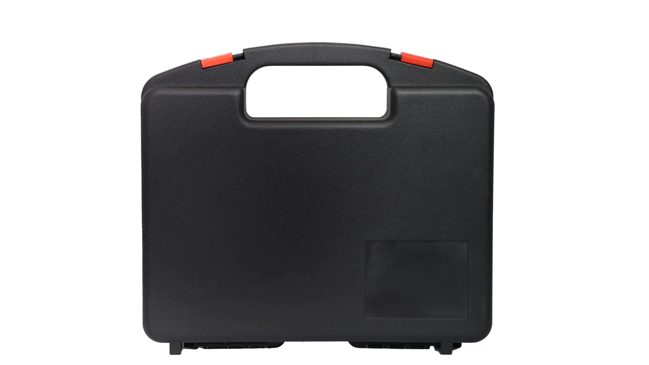
Graphite electrodes are the consumable heart of electric arc furnaces and submerged arc furnaces, yet the equipment that makes them is just as fragile. From the dies and material cylinders of an extrusion press to the fixtures and spacer blocks of a ring baking furnace, and on to the taper gauges and forming tools used on nipples, tolerances are measured in microns while the parts themselves are often brittle graphite. A single impact, one layer of conductive dust, or one rapid cooling cycle is enough to erode yield across an entire production line.
JUNZHIJIA's protection principle is simple: identify what each part fears before deciding how to pack it. Brittle graphite parts need peak-impact control, precision machined parts need micro-vibration and static control, and high-temperature returned parts need thermal-shock and residue control — three different failure mechanisms that must never share one liner logic. A protective case is not a container; it is the engineering interface that translates a transport profile into structural parameters.
Table of Contents
- Three Process Stages of Graphite Electrode Machining and What Must Be Protected
- Extrusion Forming Press: Protecting Dies, Material Cylinders and Rams
- Baking Furnace Fixtures and Spacer Parts: Heat Residue and Brittleness Risk
- Electrode Nipple Machining Parts: Taper, Thread and Conductive Face Accuracy
- Conveying and Gripping Components: Abrasive Dust Attack on Motion Pairs
- Conductive Graphite Dust and Cleanroom-Style Isolation Design
- Material and Structure Selection: Shell, Reinforcement Ribs and Wall Thickness
- Sealing Options: IP65/IP67 Against IEC 60529 and GB-T 4208
- Cushioning and Compartmentalization: Combining EPE/EVA/PE/IXPE
- Latches, Hinges and Pressure Equalization Valves
- Stacking Load Capacity and Palletized Logistics
- Temperature, Humidity, Salt Spray and Transport Test Matrix
- Customization, OEM/ODM and Acceptance Criteria
- Frequently Asked Questions FAQ
- Conclusion and Related Reading
Three Process Stages of Graphite Electrode Machining and What Must Be Protected
The standard graphite electrode route runs through batching of needle coke and petroleum coke, kneading, extrusion forming, baking, impregnation, second baking, graphitization, machining and nipple assembly. Protection targets fall into three groups by stage: the forming stage (die or mouthpiece, material cylinder liner, ram, vacuum hood, shear ring), the baking stage (fixture columns, spacer plates, trays, crucible seats, thermocouple sheaths, sagger dividers), and the machining stage (nipple taper gauges, thread gauges, face milling heads, CBN cutter discs, nipple plugs). Cross-stage conveying and gripping hardware must be added to the list — conveyor rollers, sprockets, pneumatic grippers, vacuum cups and gantry grippers.
The three groups fail for entirely different reasons. Forming parts deform and lose their mating surfaces to scratches. Baking parts crack under thermal shock and transfer pitch-coke residue. Machined parts drift under micro-vibration and short out under conductive dust. The first design step is therefore not choosing a size, but assigning every item to the correct failure class.
| Stage | Typical parts | Dominant failure mode | Protection focus |
|---|---|---|---|
| --- | --- | --- | --- |
| Extrusion forming | Mouthpiece, cylinder liner, ram | Mating-face scratches, oval bore, seized guide face | Hard-liner contact, single-part location, anti-deformation support |
| Baking | Fixture columns, spacers, crucible seats | Thermal-shock cracks, chipped corners, residue shedding | Thermal management, vertical compartments, residue zoning |
| Machining | Taper gauges, thread gauges, cutter discs | Micro-vibration drift, conductive shorting, edge chipping | Anti-vibration pads, antistatic liner, isolated cavities |
| Conveying and gripping | Rollers, grippers, vacuum cups | Bearing seizure, rail abrasion, lip wear | Dust-sealed design, pre-greasing, serviceable seal sets |
Only after this classification is complete do the three practical questions become answerable: how large should the case be, what liner should it carry, and how many parts fit. Packages that skip this step and go straight to price comparison usually reveal their weaknesses on the second return trip.
Extrusion Forming Press: Protecting Dies, Material Cylinders and Rams
A horizontal extrusion press runs with a material cylinder preheated to roughly 150–180 °C and paste at approximately 110–160 °C, pushing green electrodes of 300–700 mm diameter through the mouthpiece. The mouthpiece bore is the origin of forming accuracy; its roundness and diameter tolerance are typically held within about ±1 percent under dimensional conventions such as YB/T 4088 and ISO 10143. In practice this means that a 0.05 mm burr or dent on the working face will leave a continuous longitudinal stripe on every green body that follows.
Mouthpiece protection therefore has to work inside and out. The bore receives a PE plug or an IXPE wrap to keep hard debris out, while the outer rim and flange face rest in a profiled EVA cradle that deliberately avoids the sealing groove. Material cylinder liners run 1500–2500 mm long and are thin-walled, so they fail when supported at only two points. Any case interior must place at least three circumferential supports along the axis, and every support must land on a non-mating surface.
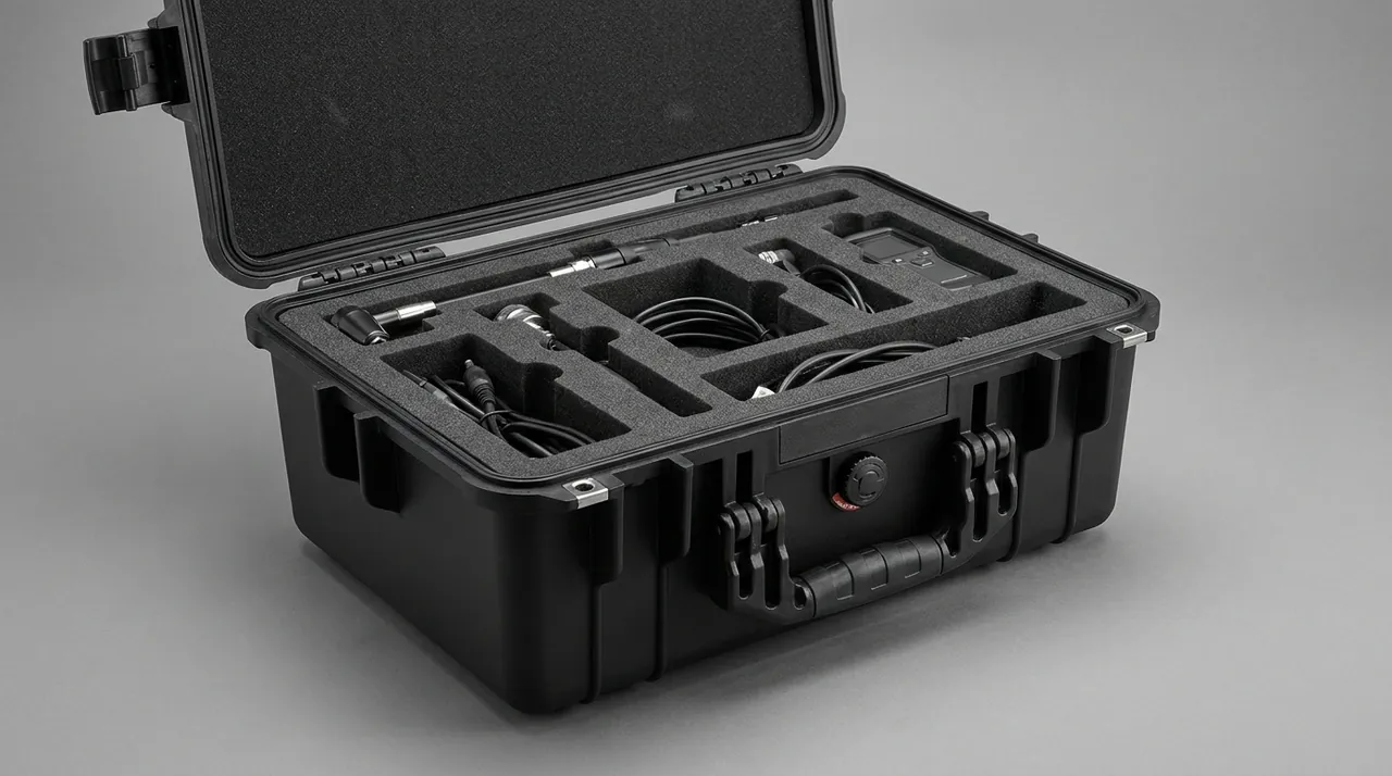
Rams and vacuum hoods are bodies of revolution with fine guide-face finishes. A vertical slot arrangement combined with a top travel stop works best: the slot is made from PE or PP, softer than steel, to prevent secondary scratching, while the stop limits axial movement to 2–3 mm.
| Part | Critical tolerance or feature | Main risk | In-case handling |
|---|---|---|---|
| --- | --- | --- | --- |
| Mouthpiece | Bore roundness, flange flatness | Bore denting, seal-face marking | Bore plug, EVA flange cradle, isolated cavity |
| Cylinder liner | Bore roundness, straightness | Bending of a slender part, end-face chipping | Three circumferential supports, axial stop, end rings |
| Ram | Guide-face finish | Guide-face scratches, edge chipping | Vertical slot, soft contact face, top stop |
| Vacuum hood | Seal-groove integrity | Groove distortion causing poor evacuation | Groove protection, compartment isolation, no top load |
Parts where the forming surface is the accuracy surface follow well-established tooling practice; the approach to parting faces and cavities in forging die cases can be reused, adjusted for the tendency of graphite paste to adhere to contact materials.
Baking Furnace Fixtures and Spacer Parts: Heat Residue and Brittleness Risk
A ring baking furnace typically operates between 1200 and 1300 °C, after which electrodes and fixtures cool slowly over several days. Fixture columns, spacer plates and crucible seats are usually graphite or high-alumina refractories. Their compressive strength is respectable, but tensile and flexural strength are weak, making them highly sensitive to point contact combined with impact. Residue makes matters worse: pitch coke and graphite powder clinging to the surface remain conductive at room temperature, so friction inside a case creates both cosmetic contamination and a shorting hazard.
Temperature management at the moment of packing deserves as much attention as the case itself. Workshop practice usually requires baked graphite parts to cool in a ventilated area to below 60 °C before entering a closed cavity. There are three reasons: rapid cooling induces thermal-stress cracking; residual heat accelerates EPDM gasket ageing; and residue plus water vapour condenses into a hard crust inside a sealed volume.
| Part | Brittle behaviour at room temperature | Pre-packing step | In-case layout |
|---|---|---|---|
| --- | --- | --- | --- |
| Fixture column | Chipped corners, end breakage | Cool to ≤60 °C, blow off residue | Vertical compartments, ≥15 mm apart |
| Graphite spacer | Face cracks, thin-edge fracture | Paper interleaving, flat, never stacked | Flat tray position, EPE interlayer |
| Crucible seat | Socket cracking | Descale, inspect socket | Single cavity with socket ring |
| Thermocouple sheath | Slender-part fracture | Sheath sleeve, vertical hang | Vertical slot with axial fixing |
Spacer plates combine thin sections with brittleness, which makes stacked storage the worst possible choice. Where quantities are large, a layered tray approach works: 3–5 mm EPE between layers, with the layer height carried by support columns rather than by the plates themselves. That last point must be marked as a mandatory requirement on the packing drawing, because it is exactly the instruction that gets ignored on a busy shop floor.
Electrode Nipple Machining Parts: Taper, Thread and Conductive Face Accuracy
The nipple is the conductive and load-bearing link between two electrodes. Its taper is commonly 1:3 or 1:4, thread fit is controlled to class 6H/6g, and the conductive contact face is often specified at Ra ≤ 3.2 µm. Taper gauges, thread gauges, face milling heads and CBN cutter discs used to produce and inspect these features are precision instruments; any impact shows up directly as excessive nipple clearance, which in service leads to overheating and joint fracture in the furnace.
The protection logic here differs from forming parts. These items see no heat, but they are extremely sensitive to micro-vibration and static. Random vibration between 5 and 50 Hz lets a gauge crawl slowly inside the case, repeatedly tapping the wall with its taper face and leaving marks that are invisible to the eye. The remedy is full constraint: soft pads on all six faces, with compression held between 20 and 30 percent so the part is held firmly without an excessive preload that could distort a thin gauge body.
| Instrument | Accuracy feature | Vibration sensitivity | Protection measure |
|---|---|---|---|
| --- | --- | --- | --- |
| Taper gauge | Contact rate ≥80 percent | High | Full EVA cradle, six-face constraint |
| Thread gauge | Pitch-diameter class 6H/6g | High | Isolated cavity, thread sleeve |
| Face milling head | Face runout ≤0.02 mm | Medium-high | Fixed cutter seat, axial locking |
| CBN cutter disc | Edge integrity | High | Edge inward, hard cover, antistatic liner |
Conveying and Gripping Components: Abrasive Dust Attack on Motion Pairs
Graphite dust sits at roughly 1–2 on the Mohs scale. It looks soft, but its fine particles embed readily in grease and turn into a classic abrasive medium. Roller bearings, sprocket pins, gripper guide rails and cylinder rods all begin to suffer three-body wear once graphite powder enters the lubricating film, and the damage becomes measurable after only a few hundred cycles. Gripping hardware faces a second problem: dust entering a vacuum cup circuit accumulates inside the ejector and steadily reduces holding force.
The protection concept is to keep dust out while leaving the part ready to run. Bearings and rails should be cleaned and re-greased before packing so they can go straight onto the machine after unpacking. Open-cell foam should be avoided inside the case, because its cellular structure traps dust and slowly releases it during the next move. Rubber items such as gripper jaws and cup lips should be removed and stored separately to prevent permanent compression set.
| Component | Ingress path | Consequence | Design response |
|---|---|---|---|
| --- | --- | --- | --- |
| Roller bearing | Lip seal area | Rising torque, noise | Double lip seal, dust shield, pre-grease |
| Chain and sprocket | Pin clearance | Pitch elongation, skipping | Separate compartment, oil-paper wrap |
| Gripper guide rail | Slider end face | Positioning drift | Dust scraper, compartment location |
| Vacuum cup | Air port | Loss of holding force | Port capping, lip stored unloaded |
Shop-floor dust strategy offers useful parallels; the zoned extraction and sealed service positions described in dust collector equipment cases translate well into debris-collection features inside a case.
Conductive Graphite Dust and Cleanroom-Style Isolation Design
Graphite dust can show volume resistivity as low as the 10⁻⁴ to 10⁻³ Ω·m range, which places it firmly in the conductive dust category. What separates it from ordinary dust is that, once settled on a terminal block, circuit board or bearing raceway, it forms a direct conductive bridge that can trigger spurious operation, partial discharge or arcing. On nipple taper faces, conductive dust can also drive galvanic corrosion points that destroy the consistency of the conductive contact.
Clean isolation inside a case is therefore not a matter of wiping parts down. It is a sequence of actions. Parts are first blown off with dry compressed air or plasma, then sealed in 0.08 mm clean PE bags with the air evacuated. Liners are specified with surface resistance between 10⁶ and 10⁹ Ω, using antistatic EVA or carbon-black modified PE. The case body carries an M5 grounding stud with resistance ≤10 Ω. Where steel parts share a case with graphite parts, a physical divider is mandatory; stretch film alone is not an acceptable barrier.
| Contamination source | Transfer path | Risk | Isolation measure |
|---|---|---|---|
| --- | --- | --- | --- |
| Graphite fines | Air settlement, friction transfer | Short circuits, spurious signals | Vacuum-sealed clean bag, antistatic liner |
| Pitch coke debris | Migration under vibration | Surface contamination, adhesion | Blow-off before packing, removable debris tray |
| Steel rust powder | Mixing with graphite dust | Conductive bridge, corrosion points | Physical divider, desiccant |
| Residual grease | Dust adhesion | Abrasive wear | Post-clean thin film, oil-absorbing paper |
If electronic components genuinely must travel in the same batch as graphite parts, the surface-resistance grading and grounding practice described in ESD antistatic protective cases brings both static and conductive dust under one control scheme.
Material and Structure Selection: Shell, Reinforcement Ribs and Wall Thickness
A graphite electrode plant contains two extremes: radiant heat around the baking area, and oil mist plus vibration sources in the forming area. Case material must balance impact resistance, thermal cycling tolerance, oil resistance and stackability. Rotomolded HDPE or MDPE bodies run 3–8 mm thick, resist impact and stay tough at low temperature, which suits heavy components. Injection-moulded PP offers tight dimensional control and complex internal geometry for instruments. Transparent PC lids suit applications needing visual confirmation. Aluminium and stainless steel suit very heavy parts and long-term storage.
Reinforcement ribs are routinely underestimated. On a rotomolded case, rib height runs three to five times wall thickness, and rib spacing of 150–250 mm markedly improves top-face compression strength. Where a packed case exceeds 80 kg gross, a steel pallet insert under the base is advisable so that metal, not plastic, carries the stacking load and long-term creep is avoided.
| Material or process | Typical wall | Low-temperature toughness | Service ceiling | Best fit |
|---|---|---|---|---|
| --- | --- | --- | --- | --- |
| Rotomolded HDPE/MDPE | 3–8 mm | Excellent, tough at -40 °C | About 70 °C | Heavy graphite parts, fixture columns |
| Injection-moulded PP | 2–4 mm | Good | About 90 °C | Instruments, small compartmented parts |
| Injection-moulded PC | 2–3 mm | Moderate, notch-sensitive | About 120 °C | Precision parts needing visibility |
| Aluminium or stainless | 1–2 mm | Excellent | High | Very heavy parts, long-term storage |
Wall-thickness consistency, demoulding radii and rib formation govern how a case behaves in a cold drop test; the mould and process discussion in rotomolded protective cases covers this in more detail.
Sealing Options: IP65/IP67 Against IEC 60529 and GB-T 4208
Ingress protection follows the IEC 60529 classification and its Chinese equivalent GB-T 4208. IP65 requires protection against water jets (6.3 mm nozzle, roughly 30 kPa, three minutes), while IP67 requires short-term immersion at 1 m for 30 minutes. These are not simply stacked levels: IP67 places far greater demands on gasket cross-section, compression and groove tolerance, because the seal must hold under a pressure head rather than a spray.
Gasket material is chosen by environment. EPDM gives good weather resistance across the ambient storage range. Silicone tolerates higher temperatures but tears more easily. NBR resists mineral oil and suits the forming area. PU foam is inexpensive but takes a large compression set and loses effectiveness after prolonged stacking. Compression is normally held between 25 and 35 percent — below 20 percent risks leakage, above 40 percent accelerates ageing.
| Gasket material | Temperature range | Oil resistance | Suggested replacement | Typical duty |
|---|---|---|---|---|
| --- | --- | --- | --- | --- |
| EPDM | -40 to 120 °C | Moderate | 3–5 years | Ambient storage, outdoor transfer |
| Silicone | -60 to 200 °C | Moderate | 4–6 years | Short-term housing of hot parts |
| NBR | -30 to 100 °C | Excellent | 3–4 years | Oily forming-area environment |
| PU foam | -20 to 80 °C | Good | 1–2 years | Light loads, short-term packing |
The difference between the spray and immersion test methods, and where each rating genuinely applies, is set out in the comparison of IP65 and IP67; the rating number should never replace a real duty assessment.
Cushioning and Compartmentalization: Combining EPE/EVA/PE/IXPE
Brittle graphite parts mean the cushioning objective is not maximum softness but keeping peak acceleration transmitted to the part below an allowable limit. Engineering practice describes this with G values: precision graphite parts and instruments are typically held below 40 g in a drop event, while heavier fixture parts may be allowed up to 60 g. The G value depends on drop height, cushion thickness and the dynamic energy absorption of the material, and must be calculated per part rather than guessed.
The four common cushioning materials have distinct roles. EPE (expanded polyethylene) rebounds well and is easy to build up in thickness, making it the main energy-absorbing layer. EVA (ethylene-vinyl acetate) is dense and thermoformable, ideal for profiled location cradles. High-density PE board is stiff and serves as a load-bearing divider. IXPE (cross-linked polyethylene) has fine, uniform cells and a smooth face, which suits interface protection on mouthpiece bores and taper faces. In practice the three are combined: EPE outside for energy absorption, EVA in the middle for location, IXPE at the contact face for fine protection.
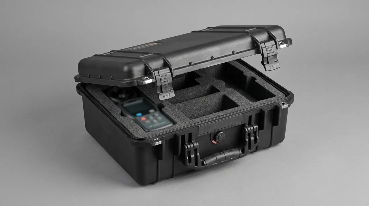
For compartmentalization, injection-moulded dividers suit regular small parts, thermoformed EVA cradles suit irregular medium parts, and removable divider systems suit mixed loads that change frequently. Whichever is used, no part may touch another and no part may strike a hard wall; a minimum spacing of 10–15 mm is recommended.
| Material | Density range | Rebound and compression set | Primary role |
|---|---|---|---|
| --- | --- | --- | --- |
| EPE | 25–35 kg/m³ | Good rebound, modest set | Main energy-absorbing layer |
| EVA | 60–120 kg/m³ | Low set, thermoformable | Profiled locating cradle |
| High-density PE board | 300–600 kg/m³ | Stiff | Load-bearing divider, base pad |
| IXPE | Cross-linked, fine cells | High recovery | Interface protection on precision faces |
How density and rebound trade off against each other is quantified in the compression-set data of the foam material comparison; those figures then need a second correction for the brittleness limit of graphite.
Latches, Hinges and Pressure Equalization Valves
A latch on a heavy graphite case must satisfy two conditions: it survives the transient shock of stacking and handling, and it lasts through enough open-close cycles. Industry practice designs metal draw latches for at least 5000 cycles, with an anti-release feature on both body and catch so that vibration cannot pop the latch in transit. Hinges should use stainless pins running in self-lubricating bushings, because graphite dust entering a dry bore will eventually cause binding.
The pressure equalization valve is the component most often overlooked on this type of case, yet it is critical. When a case passes through day-night temperature swings or the pressure change of an air shipment, the differential can reach 20–40 kPa. Without an equalization path, the interior goes into negative pressure and draws moist air in through the gasket, which produces condensation and corrosion. A valve with an expanded PTFE membrane lets air pass freely while blocking liquid water, preserving IP67 while eliminating the pressure differential.
| Component | Key metric | Common failure | Design point |
|---|---|---|---|
| --- | --- | --- | --- |
| Latch | ≥5000 cycles | Pop-open, catch cracking | Anti-release geometry, metal reinforcement |
| Hinge | Axial play ≤0.5 mm | Bore binding, pin corrosion | Stainless pin, self-lubricating bushing |
| Pressure valve | Air flow, IP67 | Membrane clogging, water ingress | Hydrophobic membrane, replaceable core |
| Handle or wheel | Static capacity ≥2× gross | Root cracking | Metal skeleton, stress-spreading washers |
Selection detail for membrane pore size, mounting orientation and replacement intervals is covered in the pressure equalization valve guide; the valve should never be mounted where dust can strike it directly.
Stacking Load Capacity and Palletized Logistics
Packed cases of graphite electrode parts commonly weigh 60–120 kg, which places them in the range that requires palletized handling. A stacking plan has to satisfy three conditions at once: the top face of a lower case must not collapse under long-term static load, the stack must not topple under vibration, and the pallet must not deflect under forklift handling. Static stacking is normally limited to two to five layers, with the top case protected by corner boards and strapping.
Several palletizing conventions are effectively mandatory. Case edges should sit flush with, or slightly inside, the pallet edge so forklift tines never strike a corner directly. Stack height including the pallet should stay at or below 1.6 m to suit most box-body vehicles. Heavy cases go at the bottom, light ones on top, with anti-slip pads between layers. For sea freight, moisture barrier wrapping and desiccant should be added to prevent condensation inside the cases during a long humid voyage.
| Parameter | Suggested value | Note |
|---|---|---|
| --- | --- | --- |
| Gross case weight | 60–120 kg | Above 120 kg, add a steel base pallet |
| Static stacking layers | 2–5 | Set by top-face capacity and storage duration |
| Stack height incl. pallet | ≤1.6 m | Fits box-body trucks and standard racking |
| Top-face design load | ≥400 kg | Verify by sustained compression test |
Temperature, Humidity, Salt Spray and Transport Test Matrix
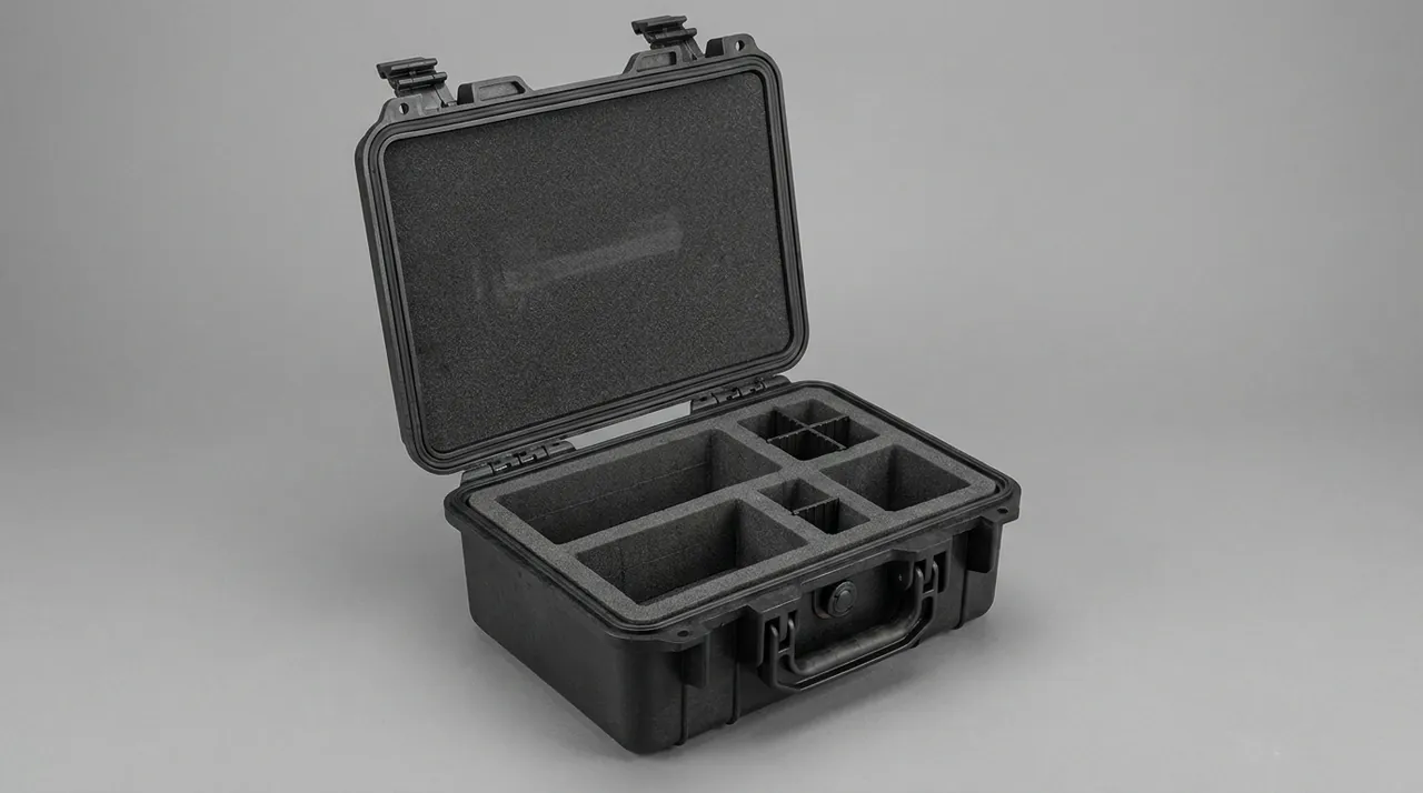
Graphite itself does not rust, but case hardware, fixture column bolts, rails and bearings do, and temperature-humidity cycling produces condensation inside the case. Environmental testing therefore cannot stop at one item. Neutral salt spray follows GB/T 10125, usually at 48, 96 or 240 hours depending on the duty environment. Thermal and damp-heat cycling follows the GB/T 2423 series. Transport testing follows the GB/T 4857 series for vibration, drop and stacking, or ISTA 1A/2A/3A, and where required the ASTM D4169 distribution cycle is used to build a test profile. Every test conclusion applies only to the submitted sample and the specified conditions.
| Test | Standard | Common level | Failure of interest |
|---|---|---|---|
| --- | --- | --- | --- |
| Neutral salt spray | GB/T 10125 | 48/96/240 h | Hardware corrosion, latch binding |
| Random vibration | GB/T 4857 / ISTA | 1A/2A/3A | Liner shift, part-to-part contact |
| Drop | ISTA / ASTM D4169 | By gross weight | Corner cracking, cushion collapse |
| Stacking | GB/T 4857 | 24–72 h static | Base-case creep, stack tilt |
| Thermal cycling | GB/T 2423 | -20 to 60 °C | Internal condensation, seal ageing |
Exact profile values should be taken from the conditions assembled in GB-T 4857 transport packaging testing and the ISTA transport testing procedures, then trimmed to the actual shipping route rather than applied as a full unfiltered set.
Customization, OEM/ODM and Acceptance Criteria
Graphite electrode equipment parts vary widely in geometry, so a standard case rarely achieves both locating accuracy and space efficiency. Customization is effectively unavoidable. The normal route runs from requirement confirmation and physical measurement, through liner concept and packing drawing approval, to prototype and trial fit, small-batch validation and finally mass production. Under ODM, the supplier also owns liner structure design and packaging validation; under OEM, work follows the buyer's drawings and tolerances strictly. Tooling and liner die cost is amortised across the project, so unit cost falls as volume rises.
Acceptance should follow the sampling rules of GB/T 2828.1, with critical items confirmed piece by piece. The criteria below serve as a starting checklist; specific values should be adjusted to the packing drawing and contract.
| Acceptance item | Example criterion | Method |
|---|---|---|
| --- | --- | --- |
| Appearance | No cracks, through-scratches or deformation | Visual and tactile |
| Dimensions | Cavity and compartment sizes match the drawing | Tape and callipers |
| Sealing | IP rating passes on sample | Spray, immersion or pressure decay |
| Liner fit | No part movement, even contact pressure | Trial fit and removal check |
| Stacking | Sustained design load without collapse | Static compression test |
| Cushioning | Peak acceleration within limit in drop | Accelerometer recording |
Frequently Asked Questions FAQ
Q: What is the essential difference between protecting green electrode bodies and protecting baked parts?
A: Green bodies are soft, pitch-bonded items with low strength that deform under modest load, so the protection focus is avoiding point loads and squeeze. The liner needs a large support area with contact placed over the mid-axial section, and full wrapping is often required because the paste surface marks easily. Baked parts have already passed through high temperature, so hardness and compressive strength rise noticeably, but brittleness increases and sensitivity to impact and corner chipping grows with it. They need soft corner blocks and should be allowed a small amount of movement inside the cushion so that energy dissipates rather than transferring into the material. A second difference appears in residue: baked parts carry pitch coke and graphite dust that must be blown off before packing, while green bodies are sticky and must be protected from dust pickup in the first place. What both share is an inability to tolerate point contact from steel parts, so every contact face must be a soft liner and no hard fastener may press directly onto a working surface.
Q: Why is graphite dust treated as conductive contamination, and what does a compliant case actually need?
A: Graphite dust has very low volume resistivity, so when it settles on terminals, circuits or raceways it forms a conductive path that can cause spurious operation or partial discharge; it cannot be handled like ordinary dust. A compliant package does four things. It blows the part clean before packing and vacuum-seals it in a clean PE bag. It specifies liner material with surface resistance between 10⁶ and 10⁹ Ω so that static charges drain instead of accumulating. It provides a grounding stud on the case body with resistance at or below 10 Ω, which only works if the liner itself is grounded through the shell. Where steel parts share the case, it uses a physical divider, because stretch film does not separate conductive media reliably under vibration. Acceptance can use a surface resistance meter on the liner and a visual plus wipe test for visible residue. The cleanliness check result should be recorded for each packing run so that a drift in shop practice is detected before it reaches the customer.
Q: How should IP65 and IP67 be chosen for graphite electrode part packaging?
A: IP65 covers water jets and suits internal workshop movement and covered truck transport. IP67 covers short-term immersion at 1 m for 30 minutes and suits open yards, rainy-region sea freight, or transfer points where standing water is possible. Do not chase the higher number automatically. IP67 demands greater gasket compression and tighter groove tolerance, it raises closing effort on a heavy lid, and if the equalization valve is configured badly the case can actually draw moisture in through negative pressure during a temperature swing. Cost also rises, because both the gasket and the moulding tolerance band tighten. A pragmatic approach is to design the body to IP67, operate day to day in an IP65 tightening state, and only fit a hydrophobic-membrane valve and run immersion verification for batches with a defined water-exposure risk. Also check which faces are exposed in the real route: a case riding on an open trailer sees spray and road grit rather than immersion, and hardware corrosion may matter more than the rating number. The rating is a test condition, not a durability promise.
Q: How should EPE, EVA and IXPE be combined to balance cost against protection?
A: The three materials do different jobs. EPE has low density, good rebound and can be built up in thickness, so it works as the main energy-absorbing layer against drop events. EVA is dense and thermoformable, which makes it the right choice for profiled locating cradles that fix a part in position and stop it crawling under vibration. IXPE has fine cells and a smooth face, so it is applied to precision working surfaces such as mouthpiece bores and taper faces where coarse cells would leave impressions. The usual combination is energy absorption outside, location in the middle, fine protection at the contact face. On cost, EPE is the most economical while EVA and IXPE carry higher unit prices, so investment should be graded by part precision rather than applied uniformly everywhere. A useful rule is to spend the premium material only on the surfaces that carry a tolerance. Thin 3 to 5 mm PE board under the base is often a better investment than a thicker EPE layer, because it stops the cushion collapsing under long-term stacking load.
Q: Why are baking furnace fixtures and spacer plates stored in vertical compartments instead of stacked?
A: These parts are mostly graphite or refractory, with reasonable compressive strength but low flexural strength. In a stack, lower parts carry the weight of everything above for a long period, and the contact points create local stress concentrations that eventually produce hidden cracks. A crack may not be visible on arrival and only opens when the fixture is loaded in the furnace, which makes the failure difficult to trace back to transport at all. Vertical compartmentalization turns gravity into an axial load along the body, putting the material in its most favourable stress state, while the gap between compartments keeps parts from touching. It also makes inspection easier, because each part can be lifted out and checked on all four sides. If quantity forces flat storage, EPE must be interleaved between layers and the layer height must be carried by support columns rather than by the plates. That requirement belongs on the packing drawing, because otherwise it gets changed on the shop floor without anyone noticing.
Q: What can be done at the packing stage to prevent graphite dust damage to roller bearings and gripper rails?
A: The realistic scope at packing is to restore the initial condition and block the ingress path. That means cleaning bearings and rails and applying fresh grease of the right viscosity before packing, so the lubricating film is at its best on first start-up rather than carrying embedded grit from the shop floor. Lip seals and dust scrapers should be checked visually and replaced where worn, because a damaged lip lets graphite powder reach the rolling elements within a few hundred cycles. Motion pairs should be wrapped in oil paper or a clean bag so dust cannot settle onto mating surfaces during transport. Rubber items such as gripper jaws and vacuum cup lips are best removed and stored separately, since prolonged compression creates a permanent set that shows up as a loss of holding force. Cylinder rods and exposed guide faces can be given a light protective film that is wiped off before assembly. These steps look trivial in isolation, but together they measurably reduce first-start-up failures and the downtime that follows them.
Q: How should moisture and rust protection for sea export relate to salt spray test results?
A: A salt spray test reports how a material or coating resists corrosion under defined conditions, but a real sea voyage combines high temperature, high humidity and airborne salt over weeks, which is a more complex exposure than the standard test reproduces. Engineering practice is to run a neutral salt spray test at 48 to 240 hours under GB/T 10125 to screen hardware and coating options, then layer practical measures on top: VCI rust-prevention bags, desiccant with a controlled initial internal humidity, and a rust-preventive oil film on exposed metal faces. Container position matters too, because a case stowed near a door sees far more condensation than one in the middle of the stack. It is important to remember that any test conclusion applies only to the submitted sample and the specified conditions, and does not automatically represent every batch across an entire voyage. The honest way to present a result of this kind is as a screening step that supports a protection plan, not as a guarantee of a rust-free arrival.
Q: From prototype to mass production, which acceptance items must be confirmed piece by piece?
A: Acceptance is best split into two groups. Items confirmed piece by piece are those tied directly to safety and use: appearance free of cracks and through-scratches, cavity and compartment dimensions matching the packing drawing, good liner fit with no part movement, and smooth latch and hinge operation. Items that can be sampled under GB/T 2828.1 are sealing performance, stacking load and cushioning peak acceleration, all of which are destructive or time-consuming; sampling ratios follow batch size and risk level rather than habit. Two further points are worth building into the contract. First, the packing drawing revision must be frozen before mass production, because a late change invalidates every liner already moulded. Second, every result belongs in the case documentation: packing drawing revision, liner material batch, test records and inspection reports.
Conclusion and Related Reading
Protecting graphite electrode equipment means answering three failure mechanisms separately: impact for brittle parts, vibration and static for precision parts, thermal shock for hot returned parts. JUNZHIJIA supplies drawings, liners, tooling and OEM/ODM.
Related Reading