

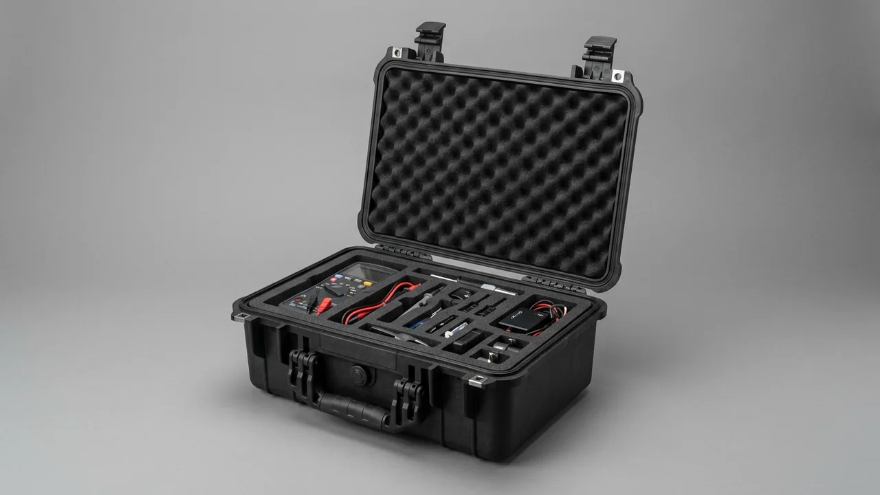
Transporting spare parts for gym and fitness equipment has a characteristic that is easy to underestimate: within a single shipment, the heaviest component and the most fragile component can differ in individual mass by three orders of magnitude. A single weight plate can reach more than ten kilograms and a complete stack can exceed one hundred kilograms, while the same case may also contain an electronic control panel less than two millimeters thick and a set of precision bearings. The design difficulty of a gym equipment parts case is not about fitting the heavy parts inside, but about letting the lifting and impact protection of the heavy weight stack, the coiling and anti-kinking of the wire rope, the anti-fretting protection of the shaft and bearing fit surfaces, and the anti-static and moisture protection of the electronic control panel coexist without interfering with one another inside one container. If any single one of these items is treated as ordinary heavy-freight packaging, the damage will surface after delivery as coating chipping, twisted rope, bearing noise, or panel failure. This article addresses four object categories, namely weight plates and stacks, pulleys and wire ropes, transmission shafts and bearings, and electronic control panels, and provides actionable solutions for zonal layout, liner selection, lifting discipline, and acceptance sampling that can be written directly into a procurement technical agreement.
The outbound logistics chain for fitness equipment is generally structured as "complete machines by container, spare parts with the machine": the complete machines are shipped in full containers, while weight parts, transmission parts, and control parts are often shipped individually as after-sales spares. This means the spare-parts case is handled repeatedly during storage and transfer, and on site very few people treat it to the standard of a precision component. Most complaints appear at the installation stage, such as chipped coating on weight plates, permanent kinks in wire rope, abnormal noise from bearings, and no display after the control panel is powered on, yet tracing the problem back usually leads to a point hundreds of kilometers earlier. The value of this article is to break the vague rule of "reinforce the heavy parts, separate the light parts" down into a zonal layout diagram, a liner density range, a coiling diameter requirement, an anti-static packaging grade, and a sampling plan that can all be written into a procurement technical agreement.
Table of Contents
- Typical Failure Modes of Gym Equipment Parts During Transit
- Weight Plates and Weight Stacks: Lifting and Impact Protection for the Heaviest Items
- Pulley Assemblies and Wire Ropes: Kinking, Twisting and Sheave Damage
- Transmission Shafts, Bearings and Pulleys: Fit Surfaces and Coaxiality Protection
- Electronic Control Panels and Sensors: Static, Moisture and Screen Protection
- Plated and Finished Parts: Scratch, Fingerprint and White Rust Prevention
- Zoning by Weight and Sensitivity: Load Logic of In-Box Layout
- Liners and Fixing: Combining EVA, EPP, Pearl Cotton and Metal Brackets
- Lifting and Handling: Lifting Points, Center of Gravity and Forklift Discipline
- Sealing, Moisture Protection and Sea Freight: Container Condensation and Salt Spray
- Case Structure and Hardware: Load Verification of Hinges, Latches and Seals
- Testing and Acceptance: GB/T 4857, ASTM D4169 and AQL Sampling
- Unpacking List, Secondary Distribution and Common Mistakes
- Frequently Asked Questions (FAQ)
- Conclusion and Further Reading
Typical Failure Modes of Gym Equipment Parts During Transit
To understand case design, one must first understand how damage occurs. The failure paths of fitness-equipment parts concentrate in roughly four categories.
The first category: secondary damage caused by the kinetic energy of heavy parts. Weight plates are the objects with the greatest kinetic energy in the whole shipment. A set of nominal 5 to 20 kg weight plates stacked into a weight stack of more than one hundred kilograms, once it gains displacement room inside the case, will transfer kinetic energy to adjacent parts when the direction changes. The common on-site observations of chipped edges, lost paint, and dented guards are mostly not caused by the first impact, but by the cumulative result of repeated small movements of the heavy part.
The second category: plastic deformation of flexible and semi-rigid parts. Wire ropes, timing belts, and sheathed cables belong to this category. A wire rope is twisted from multiple strands of fine steel wire, with single-wire diameter often below one millimeter. When the local bending radius falls below the allowable value, it enters the plastic zone and forms an irreversible "dead bend". A rope with a dead bend will jump and wear faster in the sheave groove, eventually becoming the starting point of broken wires.
The third category: fretting wear and false brinelling of fit surfaces. A ball bearing subjected to long-term vibration in a static state will produce microscopic reciprocating motion between the balls and raceways that squeezes out the lubricating film, forming indentations spaced at the ball pitch, known in the industry as false brinelling. Its symptom is periodic abnormal noise and vibration during rotation, while visual inspection often shows no abnormality, making it the most easily missed damage type at acceptance.
The fourth category: static and moisture damage to electronic parts. Control panels, sensors, and frequency converters are static-sensitive devices. The electrostatic discharge voltage on the human body or on the surface of packaging material can reach several thousand volts, far below the damage threshold of the device, and the damage may be latent, passing the factory test yet failing only days after being mounted in the complete machine. Moisture is more direct: a water film forms a leakage path on low-voltage circuits, or forms rust spots on metal pins.
| Part category | Typical unit mass | Main failure path | Packaging direction |
|---|---|---|---|
| --- | --- | --- | --- |
| Weight plates, weight stacks | 5 to 20 kg each, 50 to 150 kg per set | Coating chipping, edge impact, bottom crush | Layered tray, edge soft protection, support on main beam |
| Pulleys and pulley sets | 0.5 to 5 kg | Sheave deformation, bearing fretting, rim impact | Independent groove positioning, fretting suppression, face-contact support |
| Wire rope and cables | By length | Dead bend, twist, knot, sheath crush | Large coiling diameter, anti-twist fixing, no small bending radius |
| Transmission shaft and bearings | 1 to 20 kg | Fit surface scratch, false brinelling, anti-rust layer damage | Shaft-end protector, axial limit, low-vibration transfer |
| Electronic control panel | 0.2 to 3 kg | Static damage, screen crack, moisture oxidation | Anti-static shield packaging, rigid backing, desiccant seal |
| Chrome guide rod, galvanized hardware | 0.5 to 10 kg | Scratch, white rust, fingerprint corrosion | Inert liner, VCI rust prevention, acid-free thin paper wrap |
After understanding these four failure categories, one conclusion becomes clear: a gym equipment parts case is not one big box, but a combination of independent compartments divided by mass class and sensitivity. If the zoning is poor, no matter how thick the wall is, it cannot save the electronic parts smashed by the heavy part.
Weight Plates and Weight Stacks: Lifting and Impact Protection for the Heaviest Items
Weight plates are the "load core" of the whole case shipment. They determine the entire design of case structure, lifting points, and bottom support. Handling weight parts has three key points: lift, separate, and press.
Lifting. A complete set of weight plates, often called a weight stack or weight tower in the industry, is usually strung together by a steel guide rod. When lifting the complete set, lifting points should be set at both ends of the guide rod or on dedicated lifting lugs, rather than wrapping a steel band around the outer edge of the plates. The contact area of a steel band is small, and when tightened it forms a linear pressure on the side wall of the plates, damaging both the coating and the cast-iron edge at the same time. If a sling must be used, a wide synthetic-fiber sling with corner protectors should be applied, and the sling direction kept as parallel to the plate surface as possible. For scenarios requiring frequent single-piece handling, a dedicated tray with soft pads should be configured so that the plates are lifted by face contact.
Separation. Weight plates must be isolated piece by piece. Unseparated cast-iron plates rub against each other under vibration and produce black dust. Once this dust falls on the guide rod, pulleys, and bearings in the same case, it becomes an abrasive medium. The common practice is to insert a thin EVA or corrugated separator between each plate, with the edge wrapped by a soft guard strip. For weight plates with polyurethane (PU) coating, the separator must fully cover the coated edge, because the coating fears not frontal impact but edge shear.
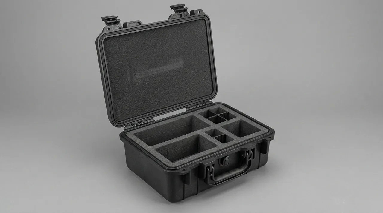
Ballast and support. The support of the weight part should fall directly on the main beam at the bottom of the case, not on the liner. The liner is responsible for spreading pressure and limiting displacement, not for carrying a static load of more than one hundred kilograms. If foam bears the self-weight of the weight stack for a long time, the foam will develop permanent compression deformation, and after transport the liner has already "collapsed", the internal clearance expands, and the heavy part moves by itself during the return or secondary distribution. The engineering approach is therefore "main beam carries load, liner positions": set a wooden beam or steel beam at the bottom, lay a buffer layer on the beam, and let the weight stack fall within the projection of the beam through a limit slot. Another benefit of zonal separation is easier on-site counting and secondary distribution. For this kind of requirement, the zonal logic of the removable divider system can be referenced.
Pulley Assemblies and Wire Ropes: Kinking, Twisting and Sheave Damage
The wire rope is the most "delicate" transmission part in fitness equipment. Its failure is usually not from breaking under tension, but from being bent badly.
Minimum coiling diameter. The allowable bending radius of a wire rope depends on the rope diameter and construction. For most 6x19 or 7x19 structure wire ropes, the coiling diameter for long-term storage usually requires not less than about twenty times the rope diameter, while the minimum wheel diameter in operation is larger. For example, a 4 mm diameter wire rope requires a long-term coiling diameter above 80 mm when calculated at twenty times. Too-small coiling forces the outer strands into the plastic zone and forms a visible dead bend. Therefore, if the case adopts "coiling" to store the wire rope, the coiling diameter must be calculated by rope diameter, not wound into a small circle to save space.
Anti-twist and anti-knot. A wire rope has a lay direction and will twist by itself in a free state. If both ends are tied at random, the rope segment will repeatedly twist and loosen during transport, forming a twist. If the rope end is not fixed, the rope body will coil itself into an "8" shape and may form a live knot. Untying a live knot creates a locally extremely small bending radius, directly causing permanent damage at the knot. The engineering treatment is: coil naturally by lay direction, fix both ends separately on a reel or drum, separate reels with partitions, and forbid multiple ropes from sharing one free space.
Sheave and pulley protection. The wheel groove of a pulley set is a fit surface, and the groove accuracy determines the contact stress distribution of the wire rope. Once the groove is dented or burred, the wire rope will be scratched when passing through, so each pulley should be placed in a contoured groove instead of stacked loosely. The bearing inside the pulley also needs fretting protection, as discussed in the next section.
| Transmission part | Protection point | Common wrong practice | Consequence |
|---|---|---|---|
| --- | --- | --- | --- |
| Wire rope (coiled storage) | Coiling diameter by rope diameter about twenty times, both ends fixed | Small circle, random end tie | Dead bend, twist, broken wire at knot |
| Wire rope (mounted on pulley) | Keep tension, pulley fixed in transit, no bending | Remove and fold in half to store | Core extrusion, sheath crush |
| Pulley and pulley set | Contoured groove, rim soft guard, fretting suppression | Loose stacking, mutual impact | Groove deformation, rim chipping |
| Timing belt and V-ribbed belt | Keep natural curvature, avoid sharp bend, avoid oil and heat | Fold at sharp angle, same box as oil | Belt core break, tooth surface indentation |
| Sheathed cable | Coiling diameter above ten times wire diameter, both ends sealed | Knot, tension tie | Core break, shield damage |
A separate reminder is needed about the practice of "removing the wire rope for transport" itself. Once removed from the pulley, the wire rope loses its original tension and support, and becomes easier to bend. Where the original mounted state can be shipped, the original state should be preferred with reinforced fixing at both ends. If removal is necessary due to packaging volume, a dedicated reel drum should be used, and the rope length, rope diameter, and corresponding machine model should be noted in the packing list to avoid errors when re-threading on site.
Transmission Shafts, Bearings and Pulleys: Fit Surfaces and Coaxiality Protection
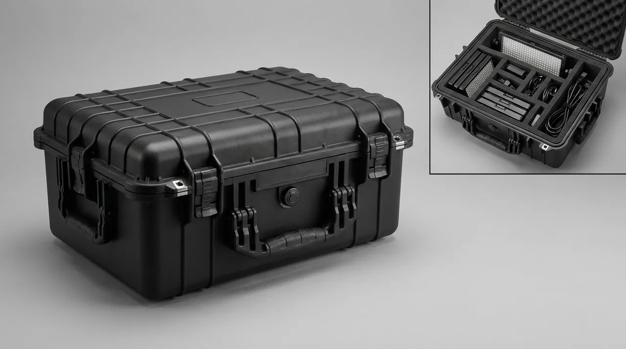
The transmission chain formed by the transmission shaft, bearing, and pulley has its precision reflected in the dimensions and coaxiality of the fit surfaces. Transport damage usually does not change the shape, but destroys the fit state.
Fit surface scratch. The shaft neck, bearing inner ring bore, and pulley taper bore are all fit surfaces, with tolerances often at the micrometer to tens-of-micrometer level. A grain of sand or a small metal chip caught between the fit surface and the lining material will pull out scratches under vibration, and the fit clearance changes accordingly. Therefore the liner surface for such parts must be clean and non-shedding, and must not share a compartment with weight parts or abrasive materials. The usual protection is to first wrap the fit section with acid-free thin paper or inert non-woven fabric, then put on a protector sleeve or cap, and finally place it in a contoured groove.
False brinelling. This is the most typical and most hidden damage in bearing transport. The bearing is subjected to vibration in a static state, and micrometer-level reciprocating fretting occurs between the balls and raceways, squeezing out the lubricant film, and cold welding and tearing of the metal surface forms indentations arranged at the ball pitch. Its three contributing conditions are: long static rest, vibration transfer, and lack of axial preload. Therefore the countermeasures are also three: shorten the transport and storage time; attenuate vibration through low-vibration-transfer liners; and apply appropriate axial light preload to the complete bearing or use radial limit to avoid fretting. For bearing units already mounted on the shaft, keeping the original mounted state is usually better than disassembling for transport.
Coaxiality and axial limit. Once the transmission shaft produces axial movement inside the case, the shaft-end spline, keyway, and shaft shoulder will collide with other parts. Therefore the liner must limit in both radial and axial directions, not just a radial groove. A longer shaft should use multi-point support, at least both ends plus the middle, to avoid bending resonance of the suspended section under vibration.
Anti-rust layer protection. The rust-proof state of transmission parts is a combination of "thin coating plus packaging environment". If the packaging material contains sulfur or chlorine, it will react with the coating under humid conditions. If the lining material absorbs water, it will form a continuously high-humidity micro-zone inside the case. Therefore the lining material in contact with shafts, bearings, and plated parts should be an inert and low-water-absorption type.
Electronic Control Panels and Sensors: Static, Moisture and Screen Protection
The electronic control panel is the only part in the whole shipment whose damage is "invisible": it may be broken down by static electricity while looking intact, or it may fail only weeks later due to moisture.
Static protection. The protection of static-sensitive devices is designed according to the three principles of "equipotential plus shielding plus grounding". At the packaging level, what can be done is: use packaging materials whose surface resistance falls in the anti-static or conductive range (the industry often divides anti-static and static-dissipative ranges by the 10^4 to 10^11 ohm level, with specific requirements based on the sensitivity grade of the device manufacturer); place the panel into a shielding bag before boxing, instead of wrapping it directly with ordinary bubble film; set up an anti-static workstation in the packing area, where operators wear wrist straps and are grounded; and avoid using easily charged ordinary polyethylene foam inside the case to directly rub the screen surface.
Moisture protection. There are three sources of moisture for electronic parts: ambient humidity, condensation water inside the container, and the "breathing effect" of the case itself. During long sea voyages, the control panel should use a moisture-barrier bag with a damp-proof layer, with desiccant inside, and the bag mouth heat-sealed or press-sealed, with a humidity indicator card placed inside. Note that the desiccant amount must be calculated by bag volume and transport duration; if insufficient, the desiccant will saturate midway and then the internal humidity will quickly follow the external environment upward.
Screen and operation surface protection. The touch screen is a glass part, resistant to compression but not to point load and bending. The protection method is "rigid back plate plus soft surface layer": cover the front of the screen with soft non-woven fabric or low-outgassing foam, add a rigid plate on the back, and place the whole into a groove, forbidding suspending pressure on the panel or strapping across the screen. The knobs, interfaces, and wire sockets on the panel should be capped or plugged to prevent foreign matter from entering during transport.
Temperature and outgassing. Electronic parts stored long term in high-temperature environments accelerate the aging of electrolytic capacitors, so the case should avoid direct sunlight and high-temperature stacking positions. At the same time, ordinary soft PVC and some foams release plasticizers and acidic gases, which form a foggy film on the panel surface after long-term sealing, affecting appearance and contact resistance. The lining material in the same box as electronic parts should be a low-outgassing type. For relevant comparison, refer to the case foam material comparison, and for the overall idea of anti-static packaging, refer to the ESD shielding case design.
Plated and Finished Parts: Scratch, Fingerprint and White Rust Prevention
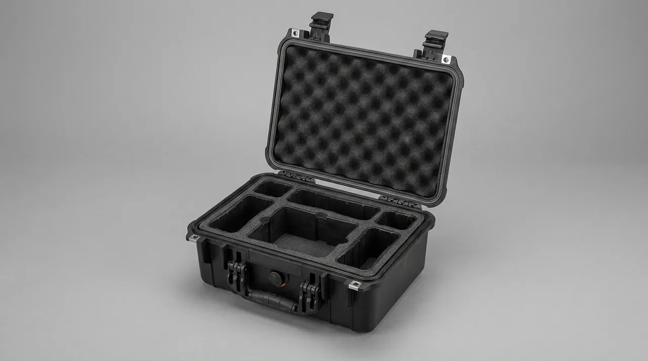
The chrome guide rods, galvanized bolts, and painted frames of fitness equipment have a dual identity of "functional part plus appearance part": they must guarantee corrosion resistance and also guarantee that the delivered appearance can be directly shelved or installed.
Scratch protection. The hardness of the chrome surface is high, but the ability to resist local scratches depends on the hardness of the opposing material and the contact pressure. The most easily overlooked scratch source is not metal, but sand grains and hard foam debris. Therefore the lining material in contact with plated parts should be clean and free of hard particles, and there should be no relative displacement between the lining and the plating. As long as zero relative slip can be maintained during vibration, the scratch probability drops significantly. This is also why plated parts should be placed in contoured grooves rather than freely placed on a flat surface.
White rust. White rust is the corrosion product of the zinc coating in a humid environment. Its conditions are "oxygen plus water film plus chloride ion", and the sea container happens to have all three. The protection logic is to cut off the water film: wrap with VCI (vapor corrosion inhibitor) paper or film to form a hydrophobic molecular layer on the metal surface, while avoiding chlorine-containing materials (such as some soft PVC and recycled paper) in direct contact with the coating, and add a moisture-barrier bag on key surfaces.
Fingerprint and hand sweat. Fingerprints form pitting sources more easily on chrome surfaces than on other surfaces, because the chloride ions in sweat act on the chrome layer under a thin water film. The standard practice is to wear clean gloves before packing, wipe with anhydrous ethanol if necessary and wrap immediately, and never touch again with bare hands after wiping.
Painted and coated parts. Painted frames resist impact better than shear, and coated parts are the same. Therefore the support for such parts must be face contact, forbidding ropes from directly binding the painted surface. In addition, painted and coated parts become brittle at low temperature, so they should not be unpacked and handled in a low-temperature state during winter transport.
| Appearance part category | Main degradation mechanism | Recommended contact material | Forbidden material |
|---|---|---|---|
| --- | --- | --- | --- |
| Chrome guide rod | Scratch, fingerprint pitting | Acid-free thin paper, inert non-woven, VCI paper | Sandy felt pad, bare hand contact |
| Galvanized hardware | White rust, friction zinc loss | VCI film, neutral packaging paper | Chlorine soft PVC, recycled board |
| Painted frame | Shear scratch, paint loss | Pearl cotton, EVA soft pad, corner strip | Direct rope bind, hard foam direct stick |
| PU coated weight plate | Edge shear damage, plasticizer migration | EVA separator, acid-free separator paper | Direct stacking, oil-containing lining |
| Stainless steel surface | Iron contamination rust spot | Dedicated stainless steel protective film | Direct contact with carbon steel parts |
Mixing stainless steel parts with carbon steel parts is a commonly overlooked detail: rust debris from carbon steel falling on the stainless steel surface will form "foreign iron contamination rust spots" in a humid environment, looking like the stainless steel itself is rusting. The two should be packed in separate zones; if separation is impossible, the stainless steel parts need independent wrapping first.
Zoning by Weight and Sensitivity: Load Logic of In-Box Layout
Zonal layout is the dividing line between a gym equipment parts case and an ordinary logistics box. The core principle of the layout has only one line: let the heaviest part obtain the lowest position and the most direct support, and let the most sensitive part obtain the most independent space and the shortest vibration path.
It expands into four rules.
Rule one: heavy parts below, light parts above, but electronic parts do not share a layer with heavy parts. Weight parts should be located directly above the main beam at the bottom of the case, reducing the center-of-gravity height and facilitating forklift and lifting. If electronic parts share a layer with heavy parts, even with a partition in between, the displacement of the heavy part will transfer impact through the partition. A feasible approach is to place electronic parts in an independent upper small compartment or side compartment, leaving a buffer gap between the compartment wall and the main compartment.
Rule two: allocate buffering by "mass times allowable acceleration". Buffer design should be calculated back from the allowable impact acceleration of the part, not allocated intuitively by weight size. The weight part has large mass and can allow slightly higher acceleration (cast iron has strong impact resistance), while the electronic part has small mass and very low allowable acceleration. If the two share the same layer of buffer, a dilemma of "heavy part finds it too soft, light part finds it too hard" appears.
Rule three: moving parts are limited separately, forbidding shared free space. Pulleys, wire ropes, and belt pulleys that will move by themselves under vibration must each have an independent limit cavity. Putting two wire ropes in the same cavity results in them twisting together; putting two pulleys in the same groove results in one pressing the other.
Rule four: make the unpacking path consistent with the packing path. Heavy spare-parts cases are often opened at a construction site or mall floor, where there may be only one manual hydraulic cart. If the part that comes out first presses on the part that comes out later, the site must move the heavy part first to get the light part, and the operation risk rises sharply. Therefore heavy parts should be placed in a position convenient for direct removal, and light parts and small parts concentrated in drawer-type or split compartments convenient for counting.
| Compartment | Object placed | Structural requirement | Unpacking priority |
|---|---|---|---|
| --- | --- | --- | --- |
| Bottom main compartment | Weight plate set, weight stack, guide rod | Main beam load, limit slot, piece-by-piece isolation | First |
| Middle groove compartment | Pulley set, belt pulley, flange | Contoured groove, axial and radial double limit | Second |
| Side vertical reel compartment | Wire rope, cable, timing belt | Reel drum, coil by lay direction, partition separate | Second |
| Upper small compartment | Bearings, bolts, small hardware | Split box, counting label | Last |
| Independent sensitive compartment | Electronic control panel, sensor | Anti-static bag, rigid back plate, buffer gap | Last |
Liners and Fixing: Combining EVA, EPP, Pearl Cotton and Metal Brackets
There is no "best" liner material, only "matching". The mass span of fitness equipment parts is large, and a single material cannot simultaneously satisfy the compression resistance of heavy parts and the soft protection of light parts, so the actual solution is almost always a multi-layer combination.
EVA (ethylene-vinyl acetate copolymer) has adjustable density, good resilience, and low permanent compression deformation, suitable for contoured grooves of precision parts and separation walls of heavy parts. Its density usually has a wide optional range; for weight plate separators, medium-low density is mostly taken to ensure fit, while for bearing and panel grooves, medium-high density is taken to ensure dimensional stability. The disadvantage of EVA is that water absorption, though low, is not zero, and long-term high-humidity environments require combined drying measures.
EPP (expanded polypropylene) has high resilience and energy absorption efficiency, resists repeated impact, and almost does not absorb water, suitable for reusable buffer blocks and corner guards. Its rigidity is good, and it can effectively cut peaks when used as a bottom buffer pad, but the surface is hard, and a soft layer must be added when in direct contact with mirror parts.
EPE (pearl cotton) has low cost, is soft, and is easy to form, suitable for surface protection layer and filling, but its permanent compression deformation is large, not suitable for long-term static load, nor as independent support for heavy parts.
Pulp molding is recyclable, stackable, and has good forming freedom, suitable for regular-shaped small and medium part trays, but its moisture resistance is poor, and maritime scenarios require moisture-proof treatment.
Metal brackets and wooden beams carry the static load. All parts exceeding a certain mass should finally transfer their static load to the main case structure through metal brackets or wooden beams, and foam is only responsible for positioning and buffering. This point is especially important for weight parts.
| Material | Typical density range | Resilience | Water absorption tendency | Applicable scenario |
|---|---|---|---|---|
| --- | --- | --- | --- | --- |
| EVA | Medium-low to high, adjustable | Good, low permanent compression | Low but not zero | Contoured groove, precision part separator, separation wall |
| EPP | Low to medium | Very good, repeated impact | Extremely low | Corner guard, bottom buffer block, reusable liner |
| EPE | Low | Average, tends to collapse under long pressure | Low | Surface protection, filling, one-time buffer |
| Pulp molding | Medium | Poor | High | Small-medium part tray, split box (needs moisture treatment) |
| Wool felt type | Medium | Good | Medium-high | Paint and plating contact surface (clean, non-color) |
| Wood beam / metal bracket | - | - | - | Carry static load, transfer to main beam |
In terms of fixing method, the combination of pressure strip, strap, and limit block is better than a single means. The strap limits the upper displacement, the pressure strip spreads the pressure, and the limit block controls the displacement within the design gap. If any one of the three is missing, a false-fixed state of "seemingly fixed but actually movable" will appear inside the case. For the design method of contoured grooves, refer to the custom foam inserts guide. Once the liner material is selected, it should also be load-verified together with the case hardware to avoid the mismatch of "very strong liner but hinge fails first".
Lifting and Handling: Lifting Points, Center of Gravity and Forklift Discipline
Accidents in lifting spare-parts cases almost all originate from two reasons: the lifting point does not match the center of gravity, and the site uses non-standard methods to lift.
Lifting point layout. The lifting points should be symmetrical to the actual center of gravity, and the resultant line of the four points must pass above the center of gravity. For a case with weight parts concentrated on one side, the center of gravity will obviously shift to that side. If the lifting points are arranged by geometric center, the case will tilt when lifted, the sling force will be uneven, and the most unfavorable sling may bear a load far above the average, which is also the typical cause of sling breakage. Therefore the lifting point position should be reconfirmed after packing according to the actual loading state, rather than fixed once at the design stage.
Lifting gear and safety factor. The design of connectors and lifting points should take a safety factor based on the case self-weight plus content weight; engineering often considers the 4:1 level, with the specific value subject to the project technical agreement and on-site lifting plan. Prefer wide synthetic-fiber slings with corner protectors, and forbid using wire rope to directly bind the case corners. For cases that need to be turned over, a dedicated turning fixture should be designed, rather than relying on manual prying.
Forklift discipline. The forklift hole position must be aligned with the center of gravity, otherwise the case will tilt forward or backward at the moment of lifting. The fork length should be greater than two-thirds of the case entry depth, avoiding excessive cantilever of the case at the fork front. The fork should be fully inserted before lifting, forbidding single-fork lifting or oblique insertion. If there is a removable skid at the bottom of the case, confirm that the connection strength of the skid and the case is sufficient to bear the local pressure of the fork.
Stacking and storage. The stacking layers of heavy spare-parts cases should be limited by the long-term static load capacity of the bottom case, not by the on-site space. The bottom case will produce creep deformation under long-term stacking, the sealing strip loses resilience after being continuously compressed, and once the case is no longer under pressure, the sealing performance also declines. Therefore the case exterior should be marked with the maximum stacking layers and "no side placement" and other storage and transport diagrams, conforming to the packaging mark idea of GB/T 191. For cases requiring multiple cycles, casters and a trolley handle should also be configured; for relevant selection, refer to the case wheels and trolley handle. The lifting experience of heavy transmission parts has something in common with the hoist component case, and can be compared for reference.
Sealing, Moisture Protection and Sea Freight: Container Condensation and Salt Spray
A large amount of fitness equipment spares are exported by sea, and sea freight happens to be the scenario that most tests moisture-proof design.
Container condensation water. When a container sails across climate zones, the day-night temperature difference can reach more than twenty degrees, and the water vapor in the air inside the box will condense into water droplets on the top plate and side walls, known in the industry as "container rain". These water droplets fall on the top of the cargo box and seep down along the gaps. There are two directions of countermeasures: first, reduce the absolute humidity inside the container (place moisture-absorbing strips in the cabinet, avoid packing in rain or high-humidity periods, control the moisture content of wooden packaging); second, improve the barrier ability of the case itself (independent sealing inside the case, waterproof eave on the case cover, no upward-opening depression on the top).
Salt spray. Coastal transport and port storage will attach chlorine-containing aerosols to the case surface, and then migrate to hardware and plated parts. The salt spray test is usually carried out according to the neutral salt spray method of GB/T 10125, used to evaluate the corrosion resistance level of hardware and coatings. For the project, the salt spray duration and acceptance judgment of hardware should be clearly required, rather than vaguely writing "anti-corrosion treatment".
Selection of sealing structure. For cases requiring moisture protection, the sealing cannot rely on only one rubber strip. The sealing effect depends on three points: the material and permanent compression deformation of the sealing strip itself, whether the case cover stiffness is sufficient to keep the entire periphery evenly compressed, and the treatment of the joint. The larger the case, the easier the cover warps in the middle, and the sealing strip will show a "air leakage channel" at the warp. Therefore heavy spare-parts cases often use stiffeners or multi-point latches to force uniform compression, and use corner-integrated sealing strips at the four corners and other failure-prone positions. For the material selection, hardness, and life evaluation of the sealing strip, refer to the case seal materials; for the strength and operation of hardware, refer to the case hinge, latch and seal.
| Sea freight risk | Action position | Typical consequence | Packaging countermeasure |
|---|---|---|---|
| --- | --- | --- | --- |
| Container condensation water | Case top and gaps | Rust spot, carton softening, electronic moisture | Cabinet dehumidify, top waterproof eave, independent seal |
| Salt spray aerosol | Case hardware, plated parts | White rust, coating peel, bolt seizure | Select by GB/T 10125, VCI protection |
| Day-night temperature breathing | Air inside case | Inner wall condensation, early desiccant saturation | Control packing moisture, increase humidity capacity |
| Long-term stacking | Case bottom and seal | Case creep, seal failure | Limit stacking layers, mark storage diagrams |
| Multiple handling | Lifting point, latch, caster | Hardware fatigue, latch loosen | Safety factor check, latch anti-loose design |
Case Structure and Hardware: Load Verification of Hinges, Latches and Seals
The hardware failure of heavy-load cases often occurs after half a year of use, because only static strength was considered at design, not fatigue and operating habits.
Hinge. The hinge bears the cantilever bending moment when opening. For a deep and heavy case, if only one hinge is set at each end, the cover will sag in the middle when open, and after long-term use the hinge shaft hole wears, the cover and case are misaligned, and the sealing strip loses uniform compression. The engineering approach is to increase the number of hinges according to the case length and select a structure with axial limit, and if necessary add an inner liner stiffener on the cover to spread the bending moment to the cover body.
Latch. The role of the latch is not only to "lock", but also to "compress the sealing strip". Therefore the locking force and distribution position of the latch directly determine the sealing performance. When the number of latches is insufficient, the cover between the two latches will lift due to the reaction force of the sealing strip. When the latch locking force is too large, the cover will produce local depression near the latch. The feasible approach is to calculate the total compression force according to the reaction force curve of the sealing strip, then distribute the number of latches according to the case length, and select a model with adjustable locking stroke. For cases requiring frequent opening, an anti-misunderstanding and anti-loosening structure should also be considered to avoid self-opening under lifting vibration.
Caster and trolley handle. Heavy cases are often pushed manually on site, and the load grade, wheel diameter, and braking mode of the caster are key. Too-small wheel diameter will jam at thresholds and ground seams, and unreliable braking has a slip risk on ramps. Note that the dynamic load capacity of the caster is usually lower than the static load capacity, and should be converted according to traffic frequency and ground conditions.
Venting and maintenance of the case. A completely sealed case will produce internal and external pressure difference under temperature difference, and the cover will be repeatedly loaded. For cases requiring sealing and also needing to withstand temperature difference, a pressure balancing structure should be set so that the pressure difference inside and outside the case is limited to a small range, while ensuring that the air permeability of the balancing structure itself is not enough to destroy the moisture-proof goal. In addition, the sealing strip needs to be replaced after long-term use, and the case should be designed so that the sealing strip can be replaced on site without damaging the case structure.
Testing and Acceptance: GB/T 4857, ASTM D4169 and AQL Sampling
Both the packaging scheme and the product itself need verification: packaging by test, product by sampling.
In terms of packaging testing, the GB/T 4857 series provides basic test methods such as drop, stacking, vibration, and impact, which is the basis of packaging verification. For export spare-parts cases requiring multiple handling, the distribution cycle framework of ASTM D4169 is closer to the actual scenario, because it combines multiple drops, vibration, and concentrated impact into one sequence. If the project needs to simulate extreme environments, the temperature, humidity, and impact test methods of MIL-STD-810H can be used as a method basis. It needs to be clarified here: citing MIL-STD-810H only means adopting its environmental test methods, and does not constitute any form of military certification. For gym equipment parts cases, the most valuable test combination is "stacking test plus random vibration plus drop test with weight parts", because these three directly correspond to the three real scenarios of sea stacking, trunk-line vibration, and on-site accidental drop. For the test framework, refer to the ASTM D4169 distribution cycle case.
In terms of product acceptance, weight and transmission parts are suitable for sampling control. Domestically, the counting sampling plan of GB/T 2828.1 is usually implemented, with general inspection level II being a common choice, and the AQL value distinguished by defect grade: defects affecting safety (such as wire rope broken wire, lifting point weld defects) take strict, and appearance defects take loose. The sampling items are recommended to cover at least the following content.
| Sampling item | Inspection method | Suggested AQL orientation | Judgment point |
|---|---|---|---|
| --- | --- | --- | --- |
| Coating and coating appearance | Visual plus touch | Loose | Chipping, bubble, color difference, scratch length |
| Plating thickness and appearance | Visual plus film thickness gauge | Medium | White rust area, bare base, thickness lower limit |
| Bearing rotation | Manual rotation plus listening | Strict | Periodic noise, stuck, axial clearance |
| Wire rope status | Visual plus touch | Strict | Dead bend, twist, broken wire, sheath damage |
| Electronic panel function | Power-on test plus static pack check | Strict | Display, touch, interface, packaging integrity |
| Internal liner and limit | Visual plus manual push-pull | Medium | Displacement, groove fit, separator complete |
| Hardware and seal | Visual plus open-close operation | Medium | Latch force, hinge gap, seal compression |
For the design of the sampling plan and the record table format, refer to the custom case acceptance AQL. It needs to be explained that sampling can only control batch quality and cannot replace packaging testing; both should be written into the technical agreement at the same time.
Unpacking List, Secondary Distribution and Common Mistakes
The life cycle of a heavy spare-parts case usually involves more than one transport. The remaining spares after the complete machine is installed, the old parts removed, and the parts reissued for after-sales will all let the same case go on the road again. Therefore reuse should be considered at design time.
The unpacking list should be attached to the case, at least including: the correspondence between case number and machine model, the part list and quantity of each compartment, the length and diameter of the wire rope, the specification and number of weight plates, and the model and serial number of electronic parts. The list is best printed on both the outer case label and the inner document bag, facilitating on-site verification without opening the case.
Secondary distribution needs to pay attention to two things. First, do not discard the removed old liner and separator; if the site replaces them with other materials, the limit will fail. Second, the case should be inspected once before reuse after the first transport: whether the sealing strip is compressed and deformed, whether the latch is loose, whether the caster is damaged, and whether the liner is compressed and collapsed. Once the liner produces permanent compression deformation, the internal clearance is inconsistent with the design value, and it should be replaced according to the original specification at this time, rather than "stuffing something to make do".
There are six common mistakes. First, believing that the weight plate is a cast-iron part and "cannot be broken", so no piece-by-piece isolation is done, resulting in coating chipping and black powder pollution at the same time upon arrival. Second, coiling the wire rope into a small circle to save space, forming a dead bend. Third, wrapping the electronic panel with ordinary bubble film, which has neither shielding nor moisture barrier. Fourth, directly contacting galvanized parts with recycled paperboard, inducing white rust. Fifth, letting foam bear the static load of the weight stack for a long time, and the liner collapses after transport. Sixth, ignoring the stacking layer limit, letting the bottom case bear pressure for a long time and causing seal failure.
Frequently Asked Questions (FAQ)
Q: Do weight plates really need a dedicated trays? Can't they just go into a wooden crate?
A: Placing them directly into a wooden crate can cope with short-distance, single-piece, light-load situations, but the risk is high in scenarios of complete weight-stack sets and long-distance transport. The problem is not the wall strength but the load transfer path: the weight plate is the object with the largest static load and kinetic energy in the whole shipment. If its self-weight all presses on the foam liner, the foam will continuously creep during the transport cycle, and after transport the liner is already compacted, the internal clearance expands, and the heavy part will move by itself during the next transport or return. At the same time, unseparated cast-iron plates rubbing under vibration produce black dust, which becomes an abrasive medium when falling on the guide rod, pulley, and bearing in the same case. Therefore the feasible approach is "main beam carries load, liner positions": set a wooden or steel beam at the bottom to bear the static load, lay a buffer layer on the beam, insert thin separators piece by piece between the weight plates, and put them into a limit slot whose projection falls within the beam range. This design has an additional benefit: during on-site counting and secondary distribution, the weight plates can be lifted out as a complete set without moving piece by piece, significantly reducing operation risk.
Q: How should wire rope be coiled to be acceptable? What is the minimum coiling diameter?
A: The criterion for acceptable coiling is that the rope body has no visible dead bend or twist after coiling, and can basically recover its natural shape after loosening. The minimum coiling diameter is related to the rope diameter and rope construction. For most 6x19 or 7x19 structure wire ropes, the coiling diameter for long-term storage usually requires not less than about twenty times the rope diameter, while the minimum wheel diameter in operation is larger. For example, a 4 mm diameter wire rope requires a long-term coiling diameter above 80 mm; a 6 mm rope requires above 120 mm. Too-small coiling forces the outer strands into the plastic deformation zone and forms an irreversible dead bend, which is also the most common starting point of wire rope failure. In addition to the diameter, there are three requirements: first, coil naturally by lay direction, do not reverse-lay forcibly; second, fix both ends separately on a reel or drum to avoid the rope segment twisting and loosening by itself during transport; third, each rope occupies a separate reel position or cavity, separated by partitions in the middle, because two ropes in the same cavity will inevitably entangle, and the pulling when untying also causes dead bends. A separate reminder is that removing the wire rope from the pulley for transport is usually more dangerous than keeping the original mounted state, because after removal it loses tension and support and becomes easier to bend.
Q: Why does a bearing develop noise after transport? How to prevent false brinelling?
A: This kind of noise usually comes from false brinelling, and its cause is not overload but the simultaneous satisfaction of three conditions: "static plus vibration plus no preload". When the bearing is subjected to continuous vibration in a static state, micrometer-level reciprocating fretting occurs between the balls and raceways, squeezing out the lubricating film, and cold welding and tearing of the metal surface finally forms shallow indentations arranged at the ball pitch. Its stealth lies in that visual inspection shows almost no abnormality, and only periodic noise and vibration appear when rotating, so it is easy to pass visual acceptance yet be exposed only after being mounted in the machine. There are three countermeasures: first, shorten the transport and storage time, because the severity of the indentation is positively correlated with the exposure time; second, reduce vibration transfer, attenuating the trunk-line vibration to a low level through low-vibration-transfer liners and bottom buffers; third, eliminate the fretting condition, applying appropriate axial light preload to the complete bearing, or using radial limit to restrict the relative fretting between balls and raceways. For bearing units already mounted on the shaft, keeping the original mounted state is usually better than disassembling for separate packaging, because disassembly loses the original preload and support. In addition, bearings in the case should not share a layer with weight parts, abrasive materials, or parts producing metal debris.
Q: Why must electronic control panels use anti-static packaging? Isn't ordinary bubble wrap enough?
A: Ordinary bubble wrap solves mechanical buffering, but not static and moisture barrier, and these two are exactly the easiest causes of electronic panel failure. In terms of static, the electrostatic discharge voltage on the human body or packaging surface can reach several thousand volts, while the damage threshold of many devices is far below this, and the damage is often latent, passing the factory function test yet failing only days after being mounted, making it hard to locate when traced. The role of anti-static packaging is to provide a shielding layer and a static dissipation path, limiting the discharge energy to a level the device can withstand. The industry often divides anti-static and static-dissipative materials by surface resistance range, with specific requirements based on the sensitivity grade given by the device manufacturer. In terms of moisture barrier, the bubble wrap itself does not block water vapor, and the panel will still absorb moisture during long sea voyages, forming a leakage path on low-voltage circuits or rust spots on metal pins. Therefore the correct approach is: first put the panel into an anti-static shielding bag with a moisture-barrier layer, place desiccant and a humidity indicator card in the bag, seal the bag mouth, then load it into an independent compartment in the case, leave a buffer gap between the compartment and heavy parts, and add a rigid plate on the back of the screen to prevent bending. Q: How to protect chrome guide rods and galvanized parts from scratches and white rust?
A: Scratch and white rust are two different mechanisms, and the countermeasures are also different. The source of scratches is usually not metal-to-metal, but sand grains, hard foam debris, and the relative slip between the lining and the plating. Therefore the key to preventing scratches has two points: the lining must be clean and free of hard particles, and the plated part must maintain zero relative slip during transport. The specific approach is to put the part into a contoured groove rather than freely on a plane, and use face-contact support rather than point contact. Fingerprints should also be avoided, because the chloride ions in sweat act on the chrome layer under a thin water film to form pitting sources. White rust is the corrosion product of the zinc coating when "oxygen plus water film plus chloride ion" are all present, and the sea container happens to satisfy these three conditions at the same time. The protection logic is to cut off the water film: wrap with VCI vapor corrosion inhibitor paper or film to form a hydrophobic molecular layer on the metal surface; avoid chlorine-containing materials in direct contact with the coating, such as some soft PVC and recycled paperboard; and add a moisture-barrier bag on key surfaces. In addition, mixing stainless steel parts with carbon steel parts will form "foreign iron contamination rust spots" in a humid environment, so the two should be packed in separate zones.
Q: Can weight parts and electronic parts be mixed in the same case?
A: Technically yes, but two prerequisites must be met: physical zoning and separate load paths. Physical zoning means the electronic part cannot be in the same free space as the weight part, and even a board in between is not enough, because the displacement of the heavy part will transfer impact through the board. The feasible approach is to place the electronic part in an independent upper small compartment or side compartment, leaving an extra buffer gap between the compartment wall and the main compartment, with the gap width designed by the maximum possible displacement of the heavy part. Separate load paths means the buffer cannot share one layer, because the weight part has large mass and relatively high allowable acceleration, while the electronic part has small mass and low allowable acceleration, and their requirements for buffer stiffness are in opposite directions. Sharing one layer will inevitably create the dilemma of "heavy part finds it too soft, light part finds it too hard"; the buffer thickness and stiffness should be calculated back separately by their respective allowable impact accelerations. Three more points need attention: the anti-static and moisture-barrier packaging of the electronic part cannot be omitted just because "it is inside the case"; the black metal dust generated by the weight part must be isolated from the electronic part, because dust on the connector causes poor contact.
Q: What lifting and forklift requirements must be written into the work instructions?
A: At least seven items should be written in. First, the lifting point position is confirmed and marked according to the actual center of gravity after packing is completed, and selecting the lifting point on site by experience is not allowed; for a case with weight parts concentrated on one side, the center of gravity is obviously shifted, and arranging lifting points by geometric center will cause the case to tilt and the sling force to be uneven. Second, the design of connectors and lifting points takes a safety factor based on the case self-weight plus content weight; engineering often considers the 4:1 level, and the allowable load is given in the document. Third, prefer wide synthetic-fiber slings with corner protectors, and forbid using wire rope to directly bind the case corners. Fourth, the forklift hole position must be aligned with the center of gravity, the fork length must be greater than two-thirds of the case entry depth, and single-fork lifting or oblique insertion is forbidden. Fifth, the case exterior should mark the center of gravity, lifting point, upward direction, tilt limit, and maximum stacking layers, conforming to the packaging mark idea of GB/T 191. Sixth, cases requiring turning should use a dedicated turning fixture, forbidding manual prying or direct rolling on the ground. Seventh, after each handling, check the tension and status of slings, latches, and straps, and record and handle any latch looseness or sealing strip displacement.
Q: What customization and documentation support can JUNZHIJIA provide?
A: JUNZHIJIA provides on-demand customized parts-case solutions for fitness-equipment spare scenarios. The typical scope includes a zonal layout drawing based on unit mass, allowable impact acceleration, and outline data; liner and metal-bracket selection with density, thickness, and compression-deformation notes; wire-rope reel and coiling-diameter design by rope diameter and lay; anti-static shield and moisture-barrier packaging with desiccant and humidity-indicator planning; and verification of lifting points, forklift holes, and stacking layers with caster or trolley interfaces reserved. On documentation, JUNZHIJIA can supply packing lists, liner drawings, assembly and disassembly sequences, material lists, self-check records, a flammability self-assessment referencing UL94, seal-level verification records, and AQL sampling records per GB/T 2828.1. Where GB/T 4857, ASTM D4169, or ISTA designated tests are required, third-party laboratory execution and reports can be coordinated. The product is manufactured by Kexin New Materials (Guangdong) Co., Ltd., with wholesale, agency, and OEM/ODM cooperation supported, and seals, separators, and spares supplied per project batch.
Conclusion and Further Reading
The essence of a gym equipment parts case is to give the load a clear path, the vibration a clear attenuation, and the sensitive parts a clear boundary. JUNZHIJIA configures liners, brackets, and protective packaging by mass class and sensitivity, providing a traceable spare-transport solution for weight, transmission, and electronic parts.
Related Reading