


A hard case must protect calibrated instruments through loading, stacking, vehicle vibration, repeated handling, and accidental drops. These events do not act on the shell in the same way. A long stacking load bends broad panels, an edge strike rotates the payload, and a corner drop concentrates energy through a very small contact zone. Temperature then changes resin stiffness, gasket recovery, latch force, and foam response. A case selected only by internal dimensions may look intact after transport while its payload has shifted, its calibration has drifted, or one portion of the seal has unloaded.
JUNZHIJIA treats hard-case protection as a coordinated system in which the shell establishes continuous load paths, corners manage impact duration, the cushioning system limits payload acceleration, and the closure maintains uniform sealing pressure. The following engineering method connects duty definition, stiffness modeling, rib geometry, wall thickness, corner reinforcement, material data, impact energy, production control, and measurable acceptance criteria.
Table of Contents
- Define the transport duty before shaping the case
- Engineer shell stiffness around complete load paths
- Balance resin modulus, wall thickness, and temperature
- Lay out ribs to control broad-panel deflection
- Reinforce corners, edges, and local attachments
- Allocate drop energy across shell and cushioning
- Select engineering plastics for the service life
- Coordinate latches, hinges, gaskets, and valves
- Match the foam system to payload fragility
- Preserve stiffness through tooling and molding
- Verify performance with an evidence-based test matrix
- Control customization, tooling, and batch acceptance
- Frequently Asked Questions FAQ
- Conclusion and Related Reading
Define the Transport Duty Before Shaping the Case
The design input is not simply a length, width, depth, and gross weight. It should identify payload mass, center-of-gravity coordinates, support points, fragile projections, allowable acceleration, calibration limits, lifting orientation, and the minimum clearance around connectors. The logistics profile must state whether one or two people carry the case, whether it rides loose or restrained in a vehicle, how many loaded units are stacked, and which temperatures can occur in a warehouse, aircraft hold, or closed truck. A 20-kilogram assembly dropped from 0.8 meter begins with roughly 157 joules of potential energy, but shell deformation, liner compression, payload mounting, rebound, and the floor divide that energy in ways that depend on orientation.
A useful requirement document separates frequent events, foreseeable misuse, and severe qualification events. Frequent events include handle cycles, trolley vibration, and routine two-high stacking. Foreseeable misuse may include a waist-height release, a short period in driving rain, or closure with one latch initially incomplete. Severe events may include a cold-conditioned corner drop or an abrupt restraint load during vehicle braking. Each event needs an acceptance statement. Cosmetic scuffing might be acceptable, while shell penetration, latch release, a broken seal line, permanent payload movement, or calibration drift is not.
Combination states matter. An empty shell test does not reproduce the bending created by concentrated payload feet. A fully loaded base may deflect at the center or around wheel mounts even though the unloaded case feels rigid. A design-input table should therefore include payload configuration and any removable trays. The overview of protective case plastic materials is useful for initial screening, but project-specific temperature, ultraviolet exposure, cleaning agents, flame behavior, and molding constraints must decide the final resin.
| Design input | Required record | Direct engineering consequence |
|---|---|---|
| --- | --- | --- |
| Payload and center of gravity | Mass and three-axis location | Base ribs, grip positions, and foam bearing area |
| Drop condition | Height plus face, edge, and corner orientations | Corner radius, deformation zone, and cushion travel |
| Stacking duty | Loaded tiers, duration, and temperature | Lid deflection and perimeter-frame stiffness |
| Environmental range | Operating, transit, and storage limits | Modulus reduction and gasket recovery margins |
| Payload fragility | Allowable acceleration and functional criteria | Foam material, thickness, and support placement |
Engineer Shell Stiffness Around Complete Load Paths
Shell stiffness is more than the force felt when a person presses the lid. A broad molded panel behaves as a plate whose bending rigidity depends strongly on elastic modulus and approximately on the cube of thickness. Increasing thickness can reduce deflection, but it also adds mass, cooling time, sink risk, and impact transmission. The first engineering task is to map a complete load path. A stack load should travel from the upper case feet into reinforced lid zones, through the perimeter frame, latch and hinge sides, into the lower shell, and finally through base feet into the next case or floor. Abrupt thinning, an isolated boss, or a sharp internal corner interrupts this path and raises local stress.
For preliminary analysis, the lid can be divided into smaller bays bounded by ribs rather than modeled as one uninterrupted plate. A comparative model should report center deflection, relative displacement along the seal frame, latch reaction, and strain at rib endings under rated stacking and proof loading. Nonlinear contact may be important because stack features engage progressively. Latch preload and foam reaction can be represented with calibrated connectors or springs, but assumptions must be written down. Material properties should represent the conditioned temperature and expected loading rate; a room-temperature initial modulus alone can overstate high-temperature stacking capability and say little about low-temperature fracture.
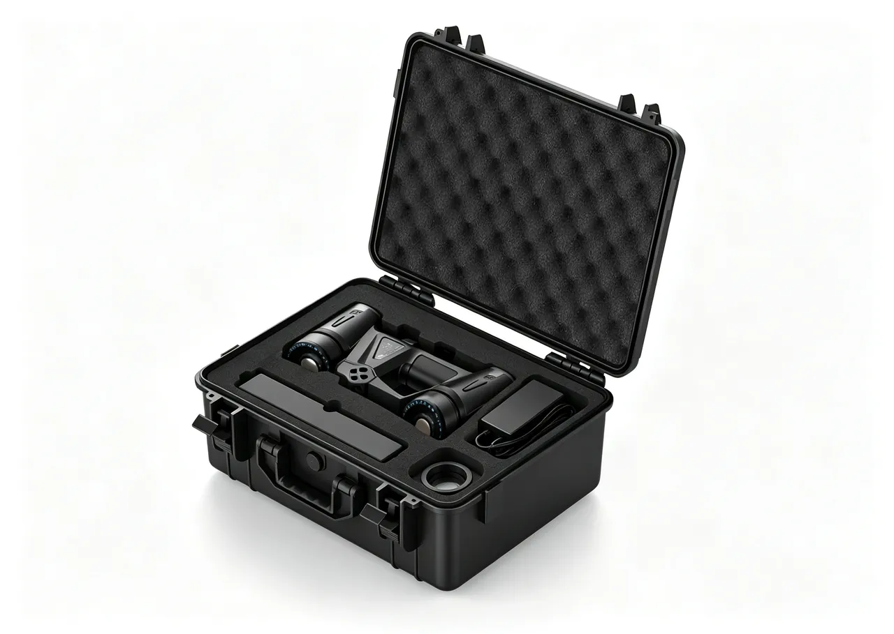
Physical correlation turns the model into an engineering tool. Apply a uniformly distributed or fixture-defined load at the actual stacking contacts, then measure displacement at the lid center, quarter points, seal frame, and latch zones. Record deflection during loading, immediately after unloading, and after a defined recovery period. A robust structure distributes reactions across the frame. If one latch carries most of the force, small production tolerances can unload the opposite gasket segment. Strain gauges or digital image correlation can further show whether a proposed rib merely changes appearance or truly diverts load into the frame.
Balance Resin Modulus, Wall Thickness, and Temperature
Polypropylene compounds, ABS, polycarbonate, and polymer blends present different combinations of modulus, density, notch sensitivity, creep, chemical resistance, and low-temperature impact performance. Designers must distinguish tensile modulus, flexural modulus, yield behavior, and impact data rather than describing a resin with one generic strength value. A hard case often experiences a moderate stack load for many days, so creep compliance may be more important than short-duration yield. A polymer that appears stiff during a room-temperature bench test can sag in a hot vehicle, reducing gasket compression or allowing the lid to contact the payload.
A practical shell uses a manufacturable nominal wall with local geometry added where required. Making every surface thick increases shot mass and creates long cooling cycles without necessarily improving corner response. Making the nominal wall too thin causes incomplete filling, read-through, and stress whitening around latches or hinges. Engineers should determine a stable thickness from projected area, resin flow length, gate strategy, and molding process, then use shallow ribs, rolled edges, generous transitions, or partial double-wall features to tune stiffness. Sudden thick-to-thin changes act like hidden hinges. Minimum measured thickness, rather than nominal CAD thickness, should be used for critical calculations.
Temperature-dependent material curves should cover the service window. At high temperature, reduced modulus and accelerated creep govern stack deformation. At low temperature, reduced ductility or greater notch sensitivity may govern a corner drop. Pigment, recycled content, fiber orientation, moisture conditioning, weld lines, and molding residual stress can move real-part performance away from data-sheet values. Coupon results therefore screen candidates but cannot qualify a finished case.
| Parameter | Intended use | Misleading shortcut | Better verification |
|---|---|---|---|
| --- | --- | --- | --- |
| Flexural modulus | Estimate panel deflection | Use only a dry 23-degree value | Test after hot and cold conditioning |
| Notched impact | Compare resin sensitivity | Treat coupon energy as case drop rating | Instrument actual molded corners |
| Wall thickness | Control stiffness and moldability | Add thickness everywhere | Measure critical sections and map variation |
| Creep response | Predict sustained stack distortion | Run a brief dead-load demonstration | Load for the specified time and temperature |
| Thermal expansion | Control lid-to-base fit | Ignore mixed-material components | Recheck seal gaps after thermal cycling |
Lay Out Ribs to Control Broad-Panel Deflection
Ribs are effective when they shorten unsupported spans and carry force into a stiffer boundary. Decorative ribs that stop in the middle of a lid may make a small zone harder to press while creating stress gradients at their ends. A grid supports loads from several directions, whereas a primary-and-secondary pattern suits a known bending axis. Wide lids can use a shallow crossed network at the center and a closed ring near the perimeter. Stack feet should align with reinforced nodes so that their reaction enters the perimeter frame instead of punching a thin panel.
Rib height, thickness, root radius, draft, spacing, and direction relative to resin flow must be considered together. An excessively thick rib creates a material concentration and sink on the opposite cosmetic face. A very thin rib may not fill, especially after long flow or across a weld line. A generous root radius lowers peak stress, but an oversized root again causes local mass and cooling imbalance. Structural analysis can first identify high strain-energy regions; mold-flow analysis can then assess fill pressure, air traps, weld lines, packing, and distortion. Prototype deflection mapping is the final calibration step.

Ribs on the inner base affect available payload space. Every protruding ledge, boss, and draft surface should appear in the liner design envelope. Foam designers should not use the external CAD outline as the usable cavity. Where stacking is required, the lid recess and base-foot pattern can follow principles described in stackable toolbox design benefits. Engagement must be deep enough to resist lateral walking but shallow and tapered enough for quick separation. Four small contacts should not become the only impact path; surrounding ribs must spread their reactions.
A design review should compare stiffness per added mass, not merely count ribs. It should also examine whether a logo recess, label panel, or flat printing zone cuts a primary load path. If a clear marking area is essential, a shallow pocket bordered by a continuous ring is usually better than removing the main cross rib. Drainage, cleaning, and foam bonding surfaces also constrain the pattern, so the most rigid theoretical lattice may not be the most reliable manufactured design.
Reinforce Corners, Edges, and Local Attachments
A corner drop is demanding because velocity components from three axes pass through a small initial contact area. Effective corner architecture combines an external radius, controlled local thickness, internal ribs that fan into three panels, and adequate clearance to the payload. A very small radius increases contact pressure and encourages cracking. A solid, excessively hard corner can shorten impact duration and pass a sharp pulse inward. A rounded outer profile with branching ribs and a controlled deformation zone spreads force without sacrificing closure integrity.
The lid and base perimeter frames form a closed section that performs several functions. They resist bending, keep the gasket compression surface aligned, and distribute latch tension. Large label pockets, hand clearances, accessory holes, or cable cutouts should not interrupt the most highly loaded frame segments. When an opening is unavoidable, bridge ribs and radiused transitions should redirect force around it. The seal land itself requires enough backing stiffness to prevent local rolling or separation during impact.
Latch and hinge mounts are high-cycle local attachments. A screw boss should not stand alone on a thin wall; gussets should connect it to the frame, and boss geometry should avoid sharp knit-line-sensitive roots. Metal inserts need controlled installation force, edge distance, and resistance to moisture or cleaning chemicals. Hinge knuckles must remain coaxial after molding and after a corner strike. Handle pivots similarly need broad load introduction because a user may lift a heavily loaded case with one grip during an awkward maneuver.
Acceptance criteria should distinguish appearance from structural evidence. Surface abrasion can be harmless, while stress whitening signals local plastic strain. Any crack, penetration, detached boss, latch release, seal-frame step, or growing hinge clearance requires investigation. After impact, use a feeler gauge or fixture to inspect frame alignment, remeasure latch operating force, torque-check specified fasteners, and inspect both empty and loaded closure. These measurements detect changes that an exterior photograph misses.
Allocate Drop Energy Across Shell and Cushioning
Potential energy, calculated from mass, gravity, and drop height, is only the starting point. During impact, energy moves into recoverable shell bending, permanent shell deformation, foam hysteresis, payload mounting, floor deformation, sound, and rebound. Protection improves when the system uses enough controlled displacement to extend the pulse without letting the payload strike the wall. A shell that is extremely rigid and a liner that is too thin can create a short, high acceleration peak. A liner that is too soft can bottom out and produce a second, even sharper event.
Instrumented tests should capture the complete acceleration-time history, not only a displayed peak. A tri-axial accelerometer in a mass-and-center-of-gravity-representative dummy can reveal pulse duration, velocity change, axis coupling, and rebound. Face drops generally expose broad-panel bending and liner compression uniformity. Edge drops introduce rotation. Corner drops challenge corner spreading and restraint in all directions. The report must state specimen temperature, conditioning time, payload mass, impact surface, actual orientation, drop height, acquisition rate, and filtering method.
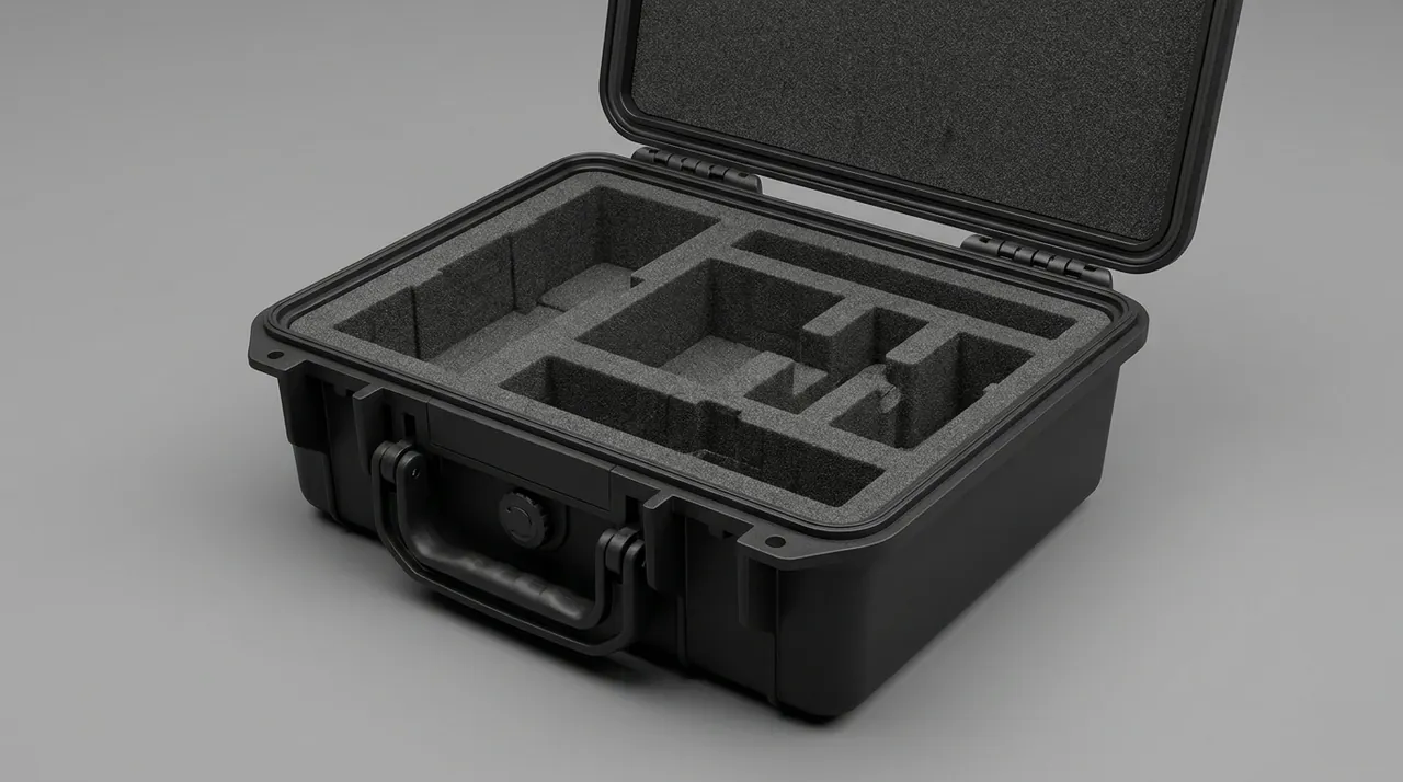
An energy ledger helps diagnose results. If the shell shows almost no deformation but payload acceleration is excessive, more controlled shell travel or cushion stroke may be needed. If the corner collapses, tears the seal frame, or shifts a latch, the load needs to spread earlier into adjacent panels. If the first pulse is acceptable but rebound creates a second damaging pulse, the foam damping and restraint geometry require adjustment. The methods outlined for a shockproof toolbox for precision tools provide additional context for matching payload fragility to system response.
Drop sequence also matters. Repeated impacts can precondition foam, grow a hidden crack, loosen hardware, or permanently change the frame. Qualification should define whether one specimen receives all orientations or separate specimens isolate each mode. The chosen sequence must be consistent between development and acceptance. Functional checks should occur at planned intervals so that engineers can identify which orientation caused a change rather than discovering failure only at the end.
Select Engineering Plastics for the Service Life
Material choice must be connected to process, environment, and required life. Toughened polypropylene compounds often provide a favorable balance of weight, impact resistance, and cost for injection-molded cases, but filler type, impact modifier, pigment, and recycled fraction can alter shrinkage and cold performance. ABS offers dimensional stability and surface quality, yet outdoor ultraviolet or low-temperature use needs specific confirmation. Polycarbonate and blends can combine stiffness with impact performance, but chemical stress cracking, drying, process control, and price may dominate the decision. Large rotationally molded polyethylene cases follow a different thickness, stiffness, and tolerance logic.
Standard coupons remain useful for comparing candidate lots, but finished molded parts incorporate weld lines, orientation, residual stress, variable cooling, engraving, and thickness transitions. Material approval should therefore lock the base resin family, additive package, color concentrate, allowed regrind, and key processing window. A supplier substitution is an engineering change, even if the generic polymer name remains the same. Incoming control can use certificate review, density or melt-flow checks, retained samples, and periodic property testing according to project risk.
Outdoor life requires ultraviolet aging followed by color, surface, impact, and closure evaluation. Coastal, laboratory, industrial, or medical use may expose the case to salt, disinfectants, fuels, oils, or cleaning concentrates. Immersion or wipe tests should look for swelling, embrittlement, loss of texture, cracking around stressed inserts, and gasket change. Compatibility must include labels and adhesives, not only the shell resin.
Long service also includes creep and fatigue. A case may remain stacked for months while its handles, latches, and hinges cycle every day during deployment. Separate tests should cover lid dead load, carry-handle cycling at rated load, latch cycles, hinge opening, wheel or skid impacts, and environmental aging. One dramatic drop cannot represent all durability modes. Outdoor case temperature extremes offers a useful framework for defining conditioning and safe operating windows, but the finished project must verify its own complete material system.
Coordinate Latches, Hinges, Gaskets, and Valves
Shell stiffness and closure performance are inseparable. Latches apply preload so the gasket maintains a target compression around the entire perimeter. Hinges control lid trajectory and alignment while carrying lid weight and occasional opening abuse. If the frame is flexible, areas beside a latch can be over-compressed while remote segments are under-compressed. Adding more latch force does not correct the underlying deformation and may accelerate gasket set or crack the latch mount.
A multiple-latch design needs repeatable engagement geometry. Hook overlap, over-center travel, mounting tolerance, lever length, and user force should produce a controlled window at every position. Engineers can measure compression with pressure-sensitive media, witness transfer, or a mapped gap method. The hinge axis must not force the gasket to scrub, roll, or lift as the lid closes. Stops or straps should prevent a fully open lid from applying prying force to the hinge bosses.
Gasket grooves require a defined cross-section, squeeze ratio, volume fill, corner radius, joint location, and surface condition. Foamed and solid elastomers differ in force, rebound, and compression set. Thermal cycling can change both the shell gap and gasket force, so leakage and operating force should be measured after conditioning. When a project targets IP65 or IP67, the agreed procedure, payload state, cable-port condition, and valve position must be documented. The discussion of system-level IP67 design explains why passing components do not automatically make a passing enclosure.
A pressure-equalization valve reduces pressure differentials created by altitude and temperature changes. Its membrane protection, airflow, water entry resistance, mounting torque, and contamination tolerance need validation. It should sit where foam, labels, user hands, and pooled water will not block it. Any drilled accessory interface requires an appropriate seal and installation control; a field-added hole can invalidate the enclosure test even though the original shell remains sound.
| Component | Key variable | Typical failure | Acceptance focus |
|---|---|---|---|
| --- | --- | --- | --- |
| Latch | Preload travel and operating force | Release, mount crack, uneven closure | Force window before and after impact |
| Hinge | Pin retention and support spacing | Pin walkout, whitening, lid misalignment | Cycle wear, axial play, and stop integrity |
| Gasket | Section, squeeze, and compression set | Discontinuous imprint or joint leakage | Uniform witness and conditioned recovery |
| Equalization valve | Airflow, water resistance, and torque | Blocked membrane or thread leakage | Pressure cycle and enclosure performance |
Match the Foam System to Payload Fragility
A foam insert should be engineered from payload response, not selected by touch. Required inputs include mass distribution, fragility or allowable acceleration, drop severity, available stroke, support surfaces, and protrusions that must remain unloaded. EPE can provide economical reusable cushioning over broad areas. EVA supports precise machining and stable presentation. PE and cross-linked PE variants offer tunable density and recovery. Density and hardness alone do not define cushioning; stress-strain behavior and dynamic cushion curves at the actual static loading are more informative. The comparison of EPE and EVA toolbox foam can guide early selection.
The cavity needs calculated clearance in all six directions. Major mass should transfer through strong chassis regions into sufficient foam area. Displays, knobs, optical windows, connectors, and antennas should sit in relief zones rather than carry load. Lid foam often prevents bounce rather than clamps the product aggressively. Excessive lid compression creates a sustained force on sensitive panels, raises latch effort, and can distort the frame. Finger pulls, accessory cavities, and cable storage must not cut through the narrowest restraint section.
Foam strain must remain within a usable range during impact. If bearing area is too large, stress may be too low and the foam barely deflects, transmitting a sharp pulse. If area is too small, it can bottom out or tear. Layering different materials can shape the response, but interfaces should not slide. Adhesive selection must suit polymer surface energy, humidity, cleaning, and temperature. A removable insert needs mechanical retention so it does not lift out with the payload.
After drop and vibration, inspection should cover payload displacement, polished rub marks, foam tears, crushed zones, bond peel, and permanent compression. Instrument response should be correlated with these physical signs. Modular layers can accommodate future payload revisions without replacing the shell tool, but every seam, removable divider, or accessory block becomes a possible slip plane. Trial fitting with a production-representative payload is essential before freezing cutting files.
Preserve Stiffness Through Tooling and Molding
A strong CAD geometry can become a weak part if filling, packing, cooling, and ejection are uncontrolled. Gate position and flow balance influence weld-line location. A weld line through a hinge mount or corner may look acceptable yet split during a cold drop. Venting affects burn marks and short filling at rib ends. Packing affects shrinkage and local density, while uneven cooling warps the seal frame. Mold-flow analysis identifies likely issues, but short shots, sectioning, dimensional studies, and destructive samples confirm what the tool actually produces.
Lid and base fit depends on coordinated shrinkage of two large molded parts. Tool temperature imbalance, ejection force, handling while warm, and storage orientation can alter diagonal dimensions and frame flatness. First-article inspection should measure critical wall sections, lid and base diagonals, latch centers, hinge-axis alignment, groove geometry, stack-feature location, and cavity envelope. Process capability on these characteristics detects drift earlier than an overall outside-length check.
Texture, engraving, and label recesses affect more than appearance. Deep texture can influence release. A logo pocket can thin a panel or interrupt a rib. Laser marking and bonding may require controlled surface chemistry. Designers should preserve the load network first and integrate branding in low-risk zones. Where a broad flat graphic surface is mandatory, surrounding geometry should restore the lost section stiffness.
Production documentation should define approved resin and color masterbatch, allowed regrind, drying when applicable, molding machine range, critical temperatures, hold pressure, cooling time, and post-mold handling. A repair to a gate, insert, rib, or seal land requires review. Material substitution, large process-window changes, or tooling repair can justify renewed fit, dead-load, impact, and leakage checks. Color approval alone cannot release a structural change.
Verify Performance with an Evidence-Based Test Matrix
The verification plan should connect every requirement to a method, specimen state, measurement, and acceptance criterion. A sensible sequence begins with dimensional and functional baselines, continues through environmental conditioning, vibration, impact, stacking, and water or dust exposure, and ends with repeat measurements and payload checks. If ISTA, ASTM D4169, or a national transport method is invoked, the contract should identify the procedure, assurance level, drop schedule, spectrum, duration, load state, and deviations. A standard name without those details is not a reproducible requirement.
| Verification | Primary observation | Example acceptance logic |
|---|---|---|
| --- | --- | --- |
| Rated stacking | Lid deflection and frame displacement | Recoverable response with normal closure afterward |
| Face, edge, and corner drops | Pulse, cracks, payload shift, latch retention | No penetration or release; payload remains functional |
| Random vibration | Resonance, fastener movement, liner abrasion | No loosening or destructive contact |
| Thermal cycling | Warpage, operating force, gasket recovery | Fit and function return within defined limits |
| Dust or water exposure | Ingress at seal, valve, and interfaces | Agreed enclosure criterion is achieved |
| Closure cycling | Latch force, hinge play, and seal wear | No fracture and force remains in its window |
Criteria must be written before testing. Allowable cosmetic abrasion, stress-whitening length, residual deflection, acceleration, calibration drift, ingress, and latch force should be quantified. Otherwise, the same observation may be accepted during development and rejected during procurement. Test photographs should identify orientation, specimen, scale, and impact point. Raw acceleration data and filter settings should be retained, not only a peak copied into a summary.
Specimen allocation and test order affect conclusions. One specimen experiencing every test represents cumulative life but makes root-cause separation difficult. Separate specimens isolate modes but can miss interaction. A balanced plan usually includes both. Measurements between stages reveal when the change began. Destructive samples and dimensional retain samples need separate identification, and payload simulators should be checked for loosened ballast or altered center of gravity.
A failure should trigger evidence-based diagnosis rather than immediate wall thickening. Inspect fracture origin, weld-line position, strain marks, foam compression, fastener torque, and time history. Then classify the root cause as requirement, architecture, detail geometry, material, molding, assembly, or test setup. A targeted correction followed by relevant regression tests is more reliable than an untracked series of heavier prototypes.
Control Customization, Tooling, and Batch Acceptance
A controlled program moves through requirement freeze, concept architecture, engineering sample, tool sample, and production approval. Requirement freeze records payload model, envelope, mass, center of gravity, interfaces, environment, compliance needs, markings, and verification matrix. Concept work compares materials, opening geometry, rib networks, corner travel, closure arrangement, and foam strategy. An engineering sample checks access, grip, clearance, and liner layout before tooling. Tool samples then reveal actual shrinkage, weld lines, stiffness, and surface condition.
OEM and ODM delivery needs a traceable bill of materials and a list of critical characteristics. Resin, pigment, latches, pins, gasket, valve, foam, adhesive, labels, and packaging documents should have controlled revisions. The principles in custom case AQL acceptance can structure visual, dimensional, and functional sampling, while destructive properties receive first-article, periodic, or change-driven verification. Initial production and major-change batches deserve increased inspection.
JUNZHIJIA can use payload geometry to review case size, wall architecture, rib placement, corner reinforcement, foam segmentation, access, and balance. Tooling, color, logos, identification plates, OEM or ODM configuration, and document packs can be planned as one controlled system. Deliverables may include approved drawings, material declarations, inspection records, test conditions, packing lists, and maintenance guidance. This makes the protection claim reviewable by engineering, quality, procurement, and field-service teams rather than dependent on an undefined description such as heavy or rugged.
Change management continues after approval. A resin source change, revised color concentrate, new foam lot, mold repair, replacement latch, different molding machine, or altered cycle can affect performance. The control plan should state which changes require notification, sample submission, dimensional comparison, or partial requalification. Retained golden samples and measured master records allow both parties to distinguish genuine process drift from normal cosmetic variation.
Frequently Asked Questions FAQ
Q: Does a thicker hard case wall always provide better drop protection?
A: No. Added thickness usually increases local bending stiffness, but it also increases mass, molding cycle time, sink risk, and the rate at which a short impact pulse can reach the payload. A successful shell needs a deliberate load path from the contact area into ribs, the perimeter frame, and adjacent panels. It should permit limited recoverable deformation without penetration, latch release, or loss of gasket alignment. The liner must then have enough working stroke to keep payload acceleration below its agreed fragility limit. Uniformly adding material can make a corner too rigid while leaving a latch boss or weld line as the weakest point. Engineers should compare alternatives with temperature-appropriate material data, minimum measured wall sections, stack-deflection tests, and instrumented drops at rated payload. Weight and hand-press feel are not adequate proxies. The best configuration is the lightest manufacturable structure that passes defined face, edge, corner, stacking, closure, and payload-function criteria with suitable production margin. This balance must remain stable across approved resin and molding variation.
Q: How should shell stiffness be selected for a particular payload weight?
A: Payload weight is necessary but insufficient. The engineer also needs center-of-gravity height, support-foot locations, contact area, allowable acceleration, handling orientation, and stack duty. A 20-kilogram chassis supported across a broad base loads the shell differently from the same mass concentrated through four small feet. Begin by setting allowable base deflection, residual set, and payload movement. Align strong payload support zones with base ribs and external feet so force crosses the shell through a short continuous path. Evaluate the lid separately under loaded stacking, including elevated-temperature creep and gasket-frame movement. During development, use a simulator that matches both mass and center of gravity, then measure base displacement and three-axis response during defined drops. Finally, fit a representative production payload to confirm clearances, connector relief, foam loading, lifting balance, and closure force. This process produces a defensible load rating; simply assigning a case by gross weight can conceal concentrated stresses and rotational impact behavior. It also overlooks how repeated handling progressively changes foam and joint response.
Q: Do more ribs automatically make a hard case lid stronger?
A: No. Ribs improve efficiency only when they shorten unsupported spans and connect loaded regions to a stiff boundary. Numerous shallow decorative ribs that terminate within a panel may add mass, trap air during molding, and create stress concentration without carrying meaningful load. The pattern should reflect loading direction: crossed or grid networks help with variable stack contacts, while primary and secondary ribs can suit a predictable bending axis. Rib thickness, height, draft, root radius, and resin-flow direction must be developed together. Thick roots create sink and cooling imbalance; thin distant ribs may not fill. Engineers should compare stiffness per added mass in structural analysis, check weld lines and packing in mold-flow analysis, and validate the design with a measured deflection grid on molded parts. Stack feet, latch reactions, hinge supports, and the perimeter frame should connect through the network. A logo or label pocket must not sever a primary rib without another geometry restoring continuity. Production measurements must then confirm that the intended rib section is consistently molded.
Q: If the shell does not crack after a corner drop, is the instrument safe?
A: Not necessarily. An uncracked shell proves only that no obvious shell fracture occurred. An overly rigid corner and a thin or poorly loaded liner can transmit a severe short pulse to the instrument while the exterior appears excellent. Corner-drop qualification should place tri-axial accelerometers in a payload simulator with representative mass and center of gravity. Review peak acceleration, pulse duration, velocity change, axis coupling, and rebound rather than one displayed number. Inspect whether the payload shifted, whether a protrusion contacted the cavity, whether foam bottomed or tore, and whether a second pulse occurred during rebound. The case itself must also retain latches, hinge alignment, seal continuity, and frame geometry. Functional checks should cover power-up, calibration, optical alignment, connectors, and any project-specific performance limit. Safe protection exists only when shell integrity, closure, sealing, restraint, cushion response, and payload function all satisfy criteria established before the test. Post-impact dimensional checks and retained sensor records are essential because hidden changes may only appear during later handling or a repeated drop.
Q: How should EVA and EPE inserts be matched to a rigid shell?
A: EVA often supports accurate machining, tidy presentation, and firm location, while EPE can deliver lightweight, economical, reusable cushioning over a broad area. Neither material can be selected from density or fingertip hardness alone. The designer should combine payload mass distribution, allowable acceleration, drop severity, available thickness, and bearing area with measured stress-strain data or relevant dynamic cushion curves. Support should enter through strong chassis zones, while displays, controls, lenses, antennas, and connectors remain relieved. Foam on the lid usually limits bounce; it should not continuously overload a sensitive panel or raise latch force excessively. If bearing stress is too low, the foam barely works and transmits a sharp pulse. If it is too high, the insert bottoms out or tears. Adhesive, layered interfaces, finger pulls, accessory cavities, and removable modules must also resist sliding. Full-payload face, edge, and corner tests confirm that the chosen materials, thicknesses, and contact areas operate in their intended strain range. Recorded compression marks help verify that the calculated load path occurred in practice.
Q: Does one successful IP67 test guarantee every use condition?
A: No. An IP67 result applies to a defined specimen, assembly state, immersion depth, exposure time, and procedure. A field-drilled hole, substituted valve, trapped cable, contaminated groove, partially closed latch, damaged gasket, or distorted frame can change the outcome. The verification plan should state whether the case is loaded, how the pressure valve and accessory ports are configured, what conditioning occurs first, and how ingress is judged. After impactful drops or thermal cycles, leakage may need to be checked again because shell alignment and gasket recovery can change. Users should keep the groove clean, inspect the gasket for cuts or compression set, and confirm complete latch engagement. The rating is not a promise for unlimited depth, duration, dynamic pressure, hot-water cleaning, or every chemical. If a customer adds an electrical bulkhead or cable gland, that finished interface requires its own controlled installation and system-level verification, even when each purchased component carries an individual rating. The completed interface, not its label alone, determines enclosure integrity.
Q: Why is elevated-temperature stacking important for hard cases?
A: Polymer response depends on both temperature and time. A lid that deflects very little during a brief room-temperature demonstration can creep during days in a hot vehicle or warehouse. As effective modulus decreases, the panel may sag into the payload, the perimeter frame may rotate, and gasket compression or latch force may become uneven. An elevated-temperature test should use the rated payload, real support and stack-contact positions, specified tier load, and a duration linked to the logistics profile. Record displacement during loading, immediately after unloading, and after a defined recovery interval. Then inspect stack features and repeat opening force, frame gap, seal witness, and any relevant ingress check. This distinguishes harmless recoverable bending from permanent deformation that threatens service life. The test temperature must come from measured or justified transport exposure rather than a convenient laboratory setting. Material creep data can guide the plan, but the complete molded case verifies ribs, wall variation, residual stress, closures, and assembly tolerances together.
Q: What is the minimum batch acceptance scope for a custom hard case?
A: Batch acceptance should cover appearance, critical dimensions, assembly function, liner fit, markings, and controlled documentation, with periodic or change-driven verification of destructive performance. Dimensional checks should include seal-frame flatness, latch and hinge locations, groove section, stack-foot geometry, critical wall areas, and usable cavity envelope. Functional checks include latch operating force, hinge motion, handle return, valve installation, empty and loaded closure, payload access, and retention. Foam inspection should verify cavity size, support location, bonding, relief around fragile features, and absence of loose debris. Labels, colors, serial identification, and packing documents must match the released revision. Resin identity, wall thickness, drop, stacking, environmental, and ingress properties cannot be destructively tested on every unit, so the control plan should combine first-article evidence, lot sampling, retained samples, and scheduled type tests. Resin substitution, mold repair, new hardware, or a major process change should trigger defined requalification rather than visual approval alone. Acceptance records should identify the lot, sample, method, instrument, result, reviewer, and applicable drawing revision for later traceability.
Conclusion and Related Reading
JUNZHIJIA integrates shell geometry, controlled impact response, closure sealing, custom foam, tooling, OEM or ODM options, and traceable documents into a hard-case design that can be measured and repeatedly accepted.
Related Reading