

Green hydrogen projects are being assembled at an accelerating pace, yet the electrolyzer itself is becoming more delicate, not less. A single megawatt-scale water electrolyzer can contain several hundred bipolar plates, an equal number of membrane electrode assemblies, porous transport layers, and sealing gaskets stacked into one pressure-loaded unit. If even one plate arrives with flatness out of tolerance, a scratched coating, a pinhole in the proton exchange membrane, or a gasket that has taken a permanent compression set, the stack will magnify that defect into a local hot spot, rising contact resistance, hydrogen-oxygen crossover, or a full line stoppage. These components travel by long-haul road, ocean container, and multiple handling steps on site, so assembly success depends on whether the measured parameters on arrival still match the values recorded at dispatch.
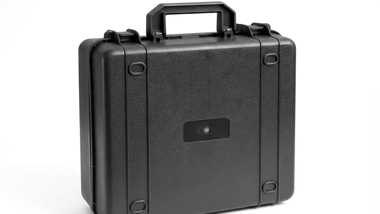
JUNZHIJIA's protection principle is that transport packaging for electrolyzer components must not stop at "it fits and nothing is lost" - it should be designed backwards from four acceptance criteria: preserved flatness, zero coating scratches, controllable membrane humidity, and deformation-free seals. The case therefore evolves from a simple container into a controlled-environment unit, combining compartmentalization, item-by-item cushioning, humidity management, pressure equalization, and cleanliness control, with stacking, vibration, drop, and salt-spray validation locking the risk down before shipment. This article covers bipolar plates, membrane electrode assemblies, porous transport layers, and seals, and sets out practical case structures, liner selection, test references, and acceptance criteria.
Table of Contents
- Why Electrolyzer Components Need Dedicated Protective Cases
- Bipolar Plate Transport Protection: Flatness, Coating, and Cleanliness
- Membrane Electrode Assemblies: Controlling Humidity Risk
- Porous Transport Layers and Gas Diffusion Layers: Brittleness and Compression Marks
- Seals and Gaskets: Compression Set and Contamination Control
- Alkaline versus PEM Electrolyzers: Comparing Protection Requirements
- Case Structure: Compartmentalization, Rigid Support, and Stacking Load
- Cushion Liner Selection: EVA, IXPE, EPE, EPP, and Polyurethane
- Sealing and Ingress Protection: IP65/IP67, IEC 60529, and Pressure Equalization Valves
- Vibration, Shock, and Stacking: ISTA, GB/T 4857, and ASTM D4169
- Cleanliness, ESD, and Metal-Ion Contamination Control
- Custom Tooling, OEM/ODM Delivery, and Acceptance Criteria
- Frequently Asked Questions
- Conclusion and Related Reading
Why Electrolyzer Components Need Dedicated Protective Cases
An electrolyzer is not a single machine but a chain of precision assemblies. In a proton exchange membrane (PEM) water electrolyzer, the anode-side bipolar plate is typically titanium with a platinum or iridium group metal coating, while the cathode side may be titanium, graphite, or a carbon composite. The membrane electrode assembly (MEA) is a catalyst-coated membrane with iridium oxide on the anode and platinum on carbon at the cathode, built on a perfluorosulfonic acid (PFSA) membrane commonly 50 to 125 microns thick. The anode porous transport layer (PTL) is sintered titanium, the cathode gas diffusion layer (GDL) is carbon paper, and alkaline electrolyzers instead combine nickel-plated steel plates, a porous diaphragm, and potassium hydroxide electrolyte.
What these components share is that their parameters shift easily and their failures are irreversible. Noble metal coatings are only sub-micron thick, so one scrape exposes the substrate. Membranes cycle between drying shrinkage and swelling, accumulating pinholes. Once a titanium felt skeleton is compressed beyond its elastic limit, local resistance stays elevated permanently. Transport concentrates these risks: random road vibration between 3 and 15 Hz drives micro-fretting, handling drops generate shock accelerations many times gravity, container temperature swings produce condensation, and loosely stacked bare plates rubbing together remain the leading cause of coating damage.
A dedicated case converts these scattered risks into one controlled boundary, and the design language is shared with adjacent equipment classes such as hydrogen fuel cell stack cases and new energy inspection protection practice.
Bipolar Plate Transport Protection: Flatness, Coating, and Cleanliness
The bipolar plate is the skeleton of the stack, carrying current, gas, and coolant at once, and its flatness determines the contact resistance distribution after assembly. Single-plate flatness is often held to roughly 0.05 to 0.10 millimeters per meter. Once a plate warps in transit, compression can no longer produce uniform contact across the active area, and the resulting local current density accelerates membrane and catalyst degradation. Warping has three causes: bare plates stacked under their own weight, unretained contents shifting under vibration, and insufficient case stiffness.
Coating protection is the second challenge. The PEM anode operates in a strongly acidic, high-potential, oxygen-evolving environment, where titanium spontaneously forms an insulating oxide, so platinum, iridium, gold, or titanium nitride coatings are required to maintain conductivity and corrosion resistance. These coatings are typically under one micron thick and highly sensitive to shear and abrasion, so scratches from sliding contact can expose the substrate and start pitting. Nickel-plated steel plates need equivalent care, because a breach in the plating becomes an initiation site in alkaline service.
The third challenge is surface cleanliness. Residual oil, fingerprints, release agents, paper fibers, and metal chips all become contamination sources, and iron, copper, nickel, and chromium ions are known to poison PFSA membranes and catalysts. Liners therefore need a cleanliness and outgassing assessment, with low-emission, sulfur-free, chlorine-free polyethylene or cross-linked polyethylene foam preferred. Packaging paper in direct contact should be neutral acid-free paper or food-grade polyethylene, never ordinary corrugated board, which releases chloride ions and dust when damp.
A workable scheme is individual isolation, compartment retention, and a rigid base. Wrap each plate in an antistatic bag or neutral interleaf, then seat it in an EVA or IXPE tray machined with accurate pockets. Size each pocket at plate thickness plus 0.5 millimeters, chamfer floors and walls to at least R3, and use vertical slots or compartmented flat placement so no plate face touches a hard surface. Allow 10 to 15 millimeters of cushion clearance between tray and case wall, filled with independent foam blocks, forming three stages: tray retention, foam energy absorption, and case load bearing.
Membrane Electrode Assemblies: Controlling Humidity Risk
The membrane electrode assembly is the highest-value and most storage-sensitive part of an electrolyzer. A perfluorosulfonic acid membrane conducts protons only when hydrated, and its water content directly drives dimensional change: linear swelling from dry to fully hydrated can exceed 10 percent. Inside a stack that strain is managed by mechanical constraint, but in a transport pack with neither constraint nor humidity buffering, two opposite failures appear. A dry environment shrinks the membrane and builds internal stress, initiating cracks or pinholes at the edge and catalyst interface, while an over-humid environment or a freeze-thaw cycle lets ice expansion damage the structure and delaminate the catalyst layer.
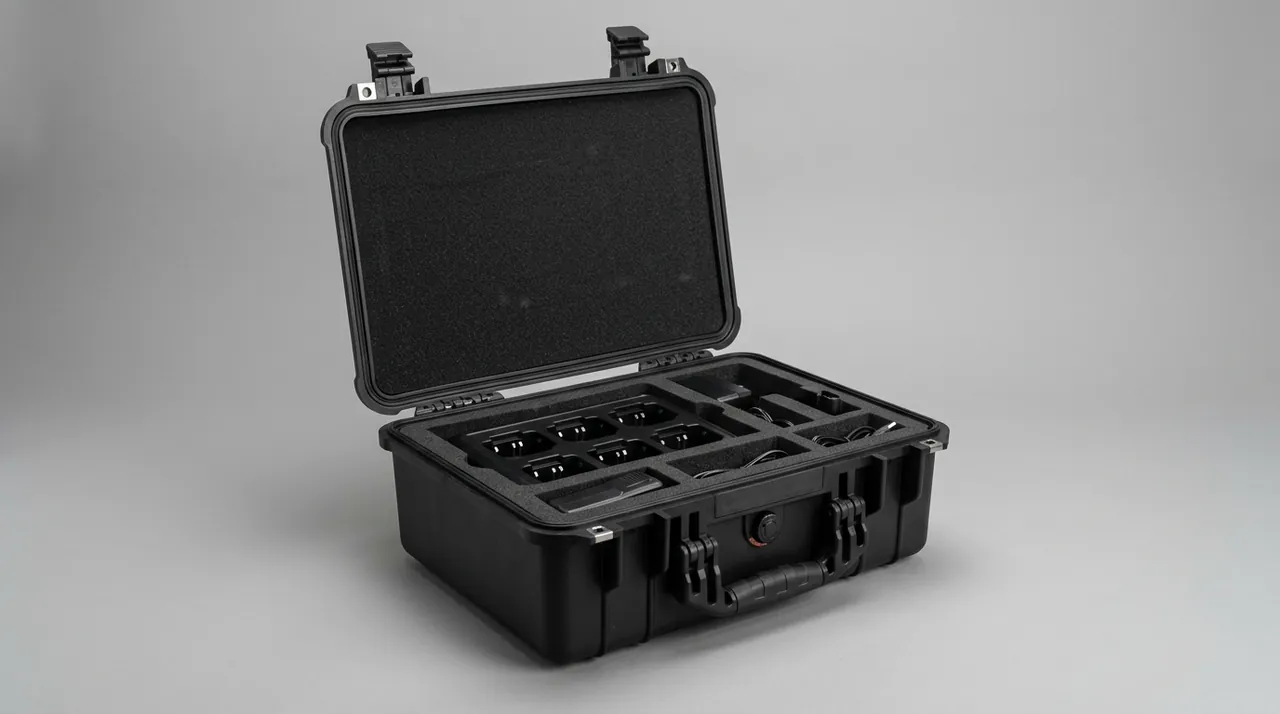
The engineering answer is to treat the MEA as a humidity-controlled precision part and build a stable micro-environment inside the pack. Aluminum foil laminate pouches under vacuum, with desiccant and a humidity indicator card, suit long ocean voyages. A sealed cavity with a small humidifying insert holds internal relative humidity between 40 and 60 percent. A hard case with dedicated humidity management, rated IP65 or better and fitted with a replaceable conditioning module, suits projects that open packs repeatedly. All three require temperature to be recorded and controlled, generally between 5 and 30 degrees Celsius.
Mechanically, MEAs must be laid flat. Folding, rolling, and hanging are prohibited, and point loads are not permitted. The tray support should match the active area outline, with a frame outside the active area so load lands on the frame rather than the membrane. Handling requires clean nitrile or cleanroom gloves; bare hands are prohibited because skin oils and sweat carry sodium, chlorine, and potassium that contaminate the catalyst and membrane.
One overlooked detail is the opening sequence. Once a humidity-controlled pack is opened, the micro-environment is lost, so exposure time must be shortened or the MEA moved to a temporary humidity cabinet. For batch drawing, a multi-cavity independently sealed design converts a whole-case opening into cavity-by-cavity drawing, as explored in custom foam insert design.
| MEA sensitivity | Typical control range | Consequence of failure | Packaging countermeasure |
|---|---|---|---|
| --- | --- | --- | --- |
| Relative humidity | 40–60% RH | Drying cracks, pinholes, delamination; freeze-thaw damage | Foil pouch with desiccant, conditioning module, indicator card |
| Temperature | 5–30 °C | Accelerated aging when hot, freeze-thaw damage when cold | Insulating liner, light shielding, temperature-controlled freight, logger |
| Stack compression | Below active-area design pressure | Membrane and catalyst compression marks, local short circuits | Frame support, height limit, interleaves |
| Contact contamination | No oil, no halogens, no metal ions | Catalyst poisoning, lower membrane conductivity | Clean gloves, clean bags, low-emission liners |
| Bend radius | Not below the specified minimum | Coating cracks, edge damage | Large core diameter, flat support, no folding |
Porous Transport Layers and Gas Diffusion Layers: Brittleness and Compression Marks
Porous transport layers and gas diffusion layers are the invisible support structures inside the stack, yet they handle mass transport, conduction, water removal, and heat transfer at once. Titanium sinter and titanium felt on the PEM anode side typically have 30 to 60 percent porosity and thicknesses from 0.2 to 1.0 millimeters, and compression beyond the elastic limit produces irreversible collapse, raising contact resistance and disturbing gas distribution. Carbon paper and carbon cloth on the cathode side are more brittle and chip easily, shedding powder that can create micro-short paths. Nickel mesh, nickel foam, and Raney nickel electrodes in alkaline systems are more ductile, but Raney nickel has a highly active surface with self-ignition and activity-loss risks on contact with air and moisture.
Protection for PTLs and GDLs can be summarized as no over-stacking, no fretting, and no contamination. No over-stacking means limiting sheets per stack and controlling total load, commonly capping height at 20 sheets or weight at 5 kilograms, with a thin closed-cell polyethylene interleaf between sheets to prevent fiber interlocking. No fretting means limiting relative movement, using low-hardness foam in surface contact rather than point contact and fully retaining each sheet in its pocket. No contamination means blocking dust and oil; an individual dust bag is the most economical measure.
Edge protection is critical for titanium felt. Cut edges carry burrs and loose fibers that can scratch adjacent parts and shed debris, so wrapping the edge with a low-emission protective tape, or placing the material in a hardened frame with chamfered corners so the frame absorbs impact energy, is recommended. Where the part has a welded frame or a sealing boss, those features need their own relief pockets so they never become load paths into the porous region.
Raney nickel and nickel-based electrodes need dry sealed packaging with desiccant and a humidity indicator, because prolonged contact with water or humid air releases heat and hydrogen. Such trays must be compatible with automated loading equipment, so gripping points, locating holes, and outline tolerances must be confirmed at the customization stage.
Seals and Gaskets: Compression Set and Contamination Control
Seals occupy an inconspicuous position in the stack but directly determine gas tightness and safety. PEM electrolyzer sealing usually uses PTFE, EPDM, FKM, or silicone, which must resist an acidic oxidizing environment, elevated temperature, and sustained compressive stress at the same time, while alkaline electrolyzers more often use EPDM and PTFE because potassium hydroxide swells and degrades many elastomers. Key metrics include hardness, commonly 70 plus or minus 5 Shore A, and compression set tested to ASTM D395 at a specified temperature and duration, with good grades below 20 percent.
The main transport threat to seals is sustained compression combined with elevated temperature. A gasket left under a heavy load, particularly where a summer container interior exceeds 60 degrees Celsius, takes an accelerated compression set. Even if it looks perfect, its rebound force after assembly is no longer sufficient to establish an effective sealing line load. Gaskets should therefore be stored loose and flat, never stacked under load, using shallow compartmented trays with separators so each gasket stays free. Gaskets supplied as roll or strip stock should use a large-diameter core and must not be strongly stretched during retention, because long-term tension produces directional residual deformation.
Contamination control matters just as much. Rubber surfaces readily adsorb oil, dust, and metal particles, which then travel with the gasket into the stack, and copper or iron in contact with rubber catalyzes aging in humid, hot conditions while introducing metal ions. Liners and separators should therefore be sulfur-free and low-emission, and operators should avoid silicone-oil release agents. For alkaline electrolyzers, gaskets must never contact aluminum parts directly, because potassium hydroxide leakage reacts violently with aluminum and releases hydrogen.
Alkaline versus PEM Electrolyzers: Comparing Protection Requirements
The electrochemical differences between alkaline and PEM electrolyzers carry straight through to packaging design. Alkaline systems use a strongly basic electrolyte that is unfriendly to aluminum and to some elastomers, and their plates are iron- and nickel-based, so anti-rust requirements outrank outgassing requirements. PEM systems use pure water in an acidic environment, with titanium and noble metal coated plates and transport layers, so cleanliness, electrostatic control, and metal-ion contamination are far more critical than rust prevention.
| Dimension | Alkaline electrolyzer components | PEM electrolyzer components |
|---|---|---|
| --- | --- | --- |
| Electrolyte and duty | Potassium hydroxide at 20%–30%, strongly basic and corrosive | Pure water, acidic, high potential, oxygen evolving |
| Separator and membrane | Porous composite diaphragm, nickel mesh composite | Perfluorosulfonic acid membrane, 50–125 microns thick |
| Bipolar plate material | Nickel-plated steel, 316L stainless steel, nickel composite | Titanium with platinum or iridium coating, graphite, carbon composite |
| Electrode and catalyst | Nickel, Raney nickel, nickel-molybdenum and nickel-iron alloys | Iridium oxide anode, platinum on carbon cathode |
| Main contamination sensitivity | Carbonation, iron ions, chloride ions | Iron, copper, nickel ions, halogens, oil, particles |
| Transport humidity requirement | Dry storage acceptable, but Raney nickel must be protected from moisture and self-ignition | Humidity must be controlled to prevent membrane drying or freeze-thaw damage |
| Case material preference | Alkali resistant, no direct aluminum contact, leak containment | Clean, low emission, antistatic, resistant to metal contamination |
| Typical ingress rating | IP65 or better, containing leaked electrolyte | IP65 or IP67, combining dust, moisture, and cleanliness control |
The real need for separate cases, liners, and labels arises at the intersection. When a project buys both alkaline and PEM components, physical segregation of packing lines, unpacking areas, and storage is advisable, with dedicated liner materials and fixtures. For alkaline parts an alkali-resistant liner bag acts as a secondary barrier; for PEM parts, liner outgassing and particle shedding must be tightly controlled. Alkaline parts justify salt-spray and alkali immersion verification, while PEM parts justify cleanliness, outgassing, surface resistance, and humidity retention checks, and edge chipping guidance in composite molding transport protection applies to composite plates.
Case Structure: Compartmentalization, Rigid Support, and Stacking Load
The case is the load-bearing skeleton of the protection system, and it determines whether cushioning and isolation can work reliably. Large heavy-duty cases are usually rotational-molded or blow-molded HDPE, mid-size precision component cases are commonly injection-molded polypropylene, and small high-cleanliness accessory cases tend toward polycarbonate or ABS. The decision is not which material is stronger in the abstract but which structure holds cavity geometry with the lowest weight and cost at the target load and environment. For flatness-critical parts such as bipolar plates, floor stiffness matters most.
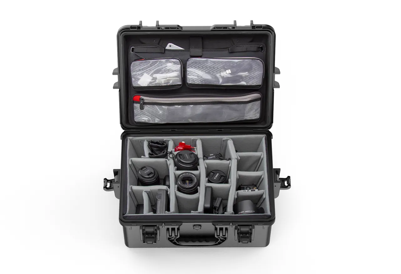
Compartmentalization converts whole-case exposure into cavity-by-cavity management. A removable divider system typically splits the interior into a main cavity for bipolar plates and MEAs, an isolated small cavity for seals, and another for fasteners, sensors, and documents. Dividers must engage the case walls reliably, loose enough to avoid shifting in transit but tight enough for easy assembly, and their height should sit below the rim so closing the lid cannot bend them. Adjustable dividers balance structural strength against flexibility when sizes vary.
Load capacity has to be established from data. The design stage should define full-load mass, stacking tiers, and lifting methods, then calculate stress distribution in the floor and walls, using ribs, load pads, and reinforced corners to route load into the walls. Stacking tests generally follow the compression and stacking procedures in the GB/T 4857 series. Latches, hinges, and handles are stress concentrators and should use metal inserts, with handle position matched to the center of gravity. Wall thickness relationships are analyzed further in wall thickness and structural design.
Cushion Liner Selection: EVA, IXPE, EPE, EPP, and Polyurethane
The liner is the damper of the protective case, absorbing impact energy through its own deformation and extending the deceleration time so the acceleration transferred to the component is reduced. Foam materials differ markedly in density, rebound, cushioning curve, temperature range, outgassing, and processing method, so selection must match component mass, fragility, support area, and transport profile rather than defaulting to the softest option. A liner that is too soft lets the component travel too far and strike a hard wall; one that is too stiff passes almost undamped shock straight through.
| Liner material | Density range | Rebound and durability | Cushioning behavior | Typical application |
|---|---|---|---|---|
| --- | --- | --- | --- | --- |
| EVA ethylene-vinyl acetate | 60–200 kg/m³ | Good rebound, multi-impact | Thermoformable into complex pockets, tunable curve | Bipolar plate locating trays, MEA flat support |
| IXPE cross-linked PE foam | 30–100 kg/m³ | Closed cell, water resistant, light | Thin interleaves, surface contact cushioning | Layer separators, thin part dividers, moisture barriers |
| EPE pearl foam | 20–40 kg/m³ | Moderate rebound, low cost | Light-load cushioning and fill | Large-part fill, non-critical retention |
| EPP expanded polypropylene | 30–90 kg/m³ | High rebound, repeated impact | Stable energy absorption, good temperature range | Heavy-duty trays, reusable transfer fixtures |
| Polyurethane PU foam | 80–500 kg/m³ | High load capacity, long life | High-density grades support heavy parts | Heavy component pads, long-life circulation fixtures |
| Antistatic modified foam | Depends on base | Matches base material | Controllable surface resistance | Electronic accessories, sensors, inspection modules |
Selection follows four steps: establish the fragility value, the maximum allowable acceleration; calculate the weight and drop-height combination to determine the required cushioning stroke; choose material and thickness from the cushioning curve so the working point sits in the effective energy-absorbing band; and verify thickness, pocket machining, assembly tolerances, and ease of loading. EVA thermoforms well and suits complex pockets; IXPE is thin and tough and suits interleaves; EPE is inexpensive but limited; EPP and high-density polyurethane suit heavy reusable transfer scenarios.
Cleanliness and safety also belong in the evaluation: liners in contact with electrodes and membranes need an outgassing assessment, avoiding sulfur-bearing accelerators, chlorinated flame retardants, and migratory plasticizers. Where components are static sensitive, antistatic foam with surface resistance in the dissipative range should be used with a defined grounding path. Thermoformed pockets should have smooth burr-free edges, die-cut sheets should not shed chips, and laminated stacks should use low-emission adhesives. A wider comparison appears in protective case foam material comparison.
Sealing and Ingress Protection: IP65/IP67, IEC 60529, and Pressure Equalization Valves
An ingress protection rating is the case's promise to the outside environment. Under IEC 60529 and its national equivalent GB/T 4208, the first digit of the IP code covers solids and dust, and the second covers water: IP65 means dust tight and protected against water jets, IP66 adds protection against powerful water jets, and IP67 adds protection against temporary immersion. For electrolyzer component transport, IP65 already satisfies most road and warehouse scenarios, while container condensation, deck transport, or ground storage where short-term flooding is possible justifies IP67. Critically, the rating belongs to the whole system: a failure in the shell, gasket, latches, or pressure equalization valve invalidates it.
Seal material and geometry are the foundation of the rating. Silicone rubber has a wide temperature range and good compression recovery; EPDM offers weathering and water resistance at moderate cost; FKM has outstanding chemical resistance where alkaline or acidic contamination is possible. Gasket compression is usually designed between 20 and 30 percent, since too little loses sealing and too much accelerates aging, and seal joints should be molded in one piece or vulcanized butt-jointed. Air-tightness or water-tightness spot testing before dispatch is strongly recommended.
The pressure equalization valve is the most commonly overlooked element in a sealed case design. A well-sealed case develops a pressure differential during air freight, high-altitude transport, or day-night temperature swings. Falling external pressure lets internal gas expand, which can force the gasket open briefly, cause a transient leak, or bulge the shell; rising external pressure creates negative pressure that makes reopening difficult and can damage latches. The solution is a valve with a waterproof breathable membrane, whose microporous PTFE film passes air slowly while blocking liquid water and particles.
Vibration, Shock, and Stacking: ISTA, GB/T 4857, and ASTM D4169
Transport testing is the bridge from design intent to verifiable performance. Packaging validation for electrolyzer components usually follows three lines: vibration, which exposes liner wear, retention failure, and resonance amplification; shock and drop, which verify corner strength and cushioning energy absorption; and stacking and compression, which verify long-term load capacity and warehouse stability. Common standards include the ISTA series, the GB/T 4857 series, and ASTM D4169, combined according to destination and transport mode.
Vibration testing normally includes sine sweep and random vibration. Sine sweep locates the resonance frequencies of the packed system; if a resonance falls inside the main energy band of transport excitation, liner stiffness, restraint, or support layout must be changed to shift it. Random vibration simulates the broadband excitation of real roads and vehicle bodies, used to assess whether liners powder or components develop fretting wear over long exposure. For surface-sensitive parts such as bipolar plates and MEAs, post-test inspection should focus on scratches on coatings and membrane surfaces and permanent compression marks in the liner.
Shock and drop conditions follow packed weight and size. Heavier packs use lower drop heights because impact energy at a given height is larger; corner, edge, and face orientations should all be covered. Internal components may need separate evaluation, for example whether titanium felt may see edge impact, and these limits belong in the technical agreement. Stacking tests replicate long-term warehouse and container loads at a specified load and duration, measuring whether post-test deformation interferes with opening or with internal condition. Validation output should form a traceable file pack, following the resonance identification approach in transport vibration testing and resonance analysis.
Cleanliness, ESD, and Metal-Ion Contamination Control
For PEM electrolyzers, cleanliness is not a refinement but a performance requirement. Membranes and catalysts are highly sensitive to metal ions; iron, copper, nickel, and chromium accumulate in the membrane, lower conductivity, catalyze radical formation, and accelerate degradation, while chlorides and sulfides can poison catalyst active sites directly. Conductive particles can pierce the membrane and create a short circuit, and insulating particles can block porous transport layer channels, causing local dry-out and hot spots. Liner selection, case surface treatment, and the handling environment should therefore be designed around low outgassing, low particle generation, and low ion release.
Cleanliness can be quantified using cleanroom classification. ISO 14644 grades the number of particles of different sizes per cubic meter of air, with lower numbers indicating cleaner environments. Packing does not need semiconductor-grade cleanrooms, but a controlled area is advisable, avoiding workshops with dust, oil mist, and metalworking. Liners should be tested for particle shedding and outgassing, case interiors should be smooth to reduce dust traps, and higher-specification projects can add a clean film bag as a secondary barrier.
Electrostatic control is especially important for components that include electronic accessories or sensors. Electrostatic discharge can damage sensor circuits, contaminate sensitive surfaces, and attract particles. Common practice is to specify antistatic foam and packaging bags with surface resistance in the dissipative range and to ensure a connectable grounding path from the case. Where the component itself must not be grounded, fully dissipative materials allow slow charge decay instead. Antistatic performance changes with humidity, aging, and contamination, so periodic retesting is needed. Where both cleanliness and ESD requirements apply, selection should confirm that the two properties coexist without adding new outgassing risk from modification additives.
Metal hardware inside the case must also serve the contamination-control goal. Bare carbon steel and zinc-plated parts release iron and zinc ions in humid conditions, so internal fasteners, hinge inserts, and brackets should be 304 or 316 stainless steel or anodized aluminum, and must not contact components directly. Cleaning should use isopropyl alcohol and deionized water; chlorinated solvents and silicone-oil conditioners are prohibited. Where a complete clean-control process is needed, the zoning and fixture practices in cleanroom equipment protection and transfer provide a template.
Custom Tooling, OEM/ODM Delivery, and Acceptance Criteria
Electrolyzer component dimensions span a wide range, from near-square-meter bipolar plates to palm-sized sensors and fittings, so standard cases rarely balance protection against loading efficiency. Customization falls into three tiers: selecting an existing case size and customizing only the liner pockets, which is fast and low investment; adjusting case dimensions and structure with a new liner tool, balancing protection and payload efficiency; and developing the full case and liner system around component geometry and line takt. The right tier depends on component value, batch size, handling method, and project timeline.
OEM/ODM cooperation also requires clear terms on intellectual property and tool ownership, minimum order quantity, schedule flexibility, change management, and after-sales response. For high-value cargo, version control of the packaging specification should be written into the contract, because any structural or liner change invalidates earlier test conclusions. If an anomaly appears on site, the case label and batch records should trace back to the liner batch, test report, and operator. Supplier comparison frameworks are covered in custom protective case OEM/ODM guide and supplier evaluation systems.
After packing, a label fixed in a consistent position should record component name, specification, batch, quantity, packing date, shelf life, and transport precautions, with a QR code for scanning verification. For products with temperature and humidity requirements such as membrane electrode assemblies, an in-case logger provides full-chain data traceability. The cases described are supplied with customization support by JUNZHIJIA, which can issue a complete packing scheme and validation file set from the actual project component list.
Frequently Asked Questions
Q: Why can't electrolyzer bipolar plates simply be stacked directly on top of each other?
A: Bare stacking triggers three risks at once. Mechanically, plates creep slightly under sustained self-weight combined with vibration, and the taller the stack, the greater the load and friction shear on the bottom layers, so flatness after transport often falls outside assembly tolerance and cannot be corrected later. On the surface side, coatings are typically under one micron thick, and repeated micro-sliding between plates abrades the coating and flow-field ridges, exposing the substrate and driving up both corrosion and contact resistance. On the cleanliness side, carbon plates rubbing together shed carbon powder that can create micro-short paths inside the stack, while metal debris poisons the membrane and catalyst. The correct approach is to wrap each plate individually in neutral interleaf paper or a clean polyethylene bag, then seat it in a foam tray with machined locating pockets, using vertical slots or compartmented flat placement, with pocket width sized at plate thickness plus clearance and pocket floors chamfered to avoid stress concentration, while total tray weight and stacking tiers stay strictly limited.
Q: How should membrane electrode assemblies be humidity-controlled in transit so they do not arrive already damaged?
A: The core of an MEA is a perfluorosulfonic acid membrane whose conductivity depends on hydration, and changes in water content can produce more than ten percent linear dimensional change, which is enough to crack a constrained or unsupported membrane. In a dry environment the membrane shrinks and develops internal stress, readily initiating cracks or pinholes at the edge and catalyst interface; in an over-humid environment combined with freezing, ice expansion inside the membrane damages the structure just as effectively, so humidity control must work in both directions rather than simply drying the pack. Three approaches are common: an aluminum foil laminate pouch with desiccant and a humidity indicator card for long ocean voyages; a sealed cavity with a small conditioning insert holding internal relative humidity between forty and sixty percent; and a hard case with a replaceable conditioning module for projects that open packs repeatedly for inspection. Whichever is chosen, temperature should be held between five and thirty degrees Celsius. Mechanically, MEAs must lie flat, with folding and point loads prohibited, and clean gloves are mandatory during handling.
Q: Can alkaline and PEM electrolyzer components share the same protective case design?
A: Sharing is not advisable, because their contamination sensitivities and chemical compatibility are nearly opposite, and a compromise design tends to leave a hidden hazard on one side. Alkaline systems use potassium hydroxide at twenty to thirty percent by mass, a strong base that reacts violently with aluminum and releases hydrogen, so no aluminum part may contact alkaline residue directly and an alkali-resistant liner bag is needed as a secondary barrier, while iron corrosion and carbon dioxide enrichment must also be avoided. PEM systems use pure water in an acidic, high-potential environment, and their plates and transport layers are titanium with noble metal coatings, making them highly sensitive to oil, halogens, particles, and iron, copper, and nickel ions, so liners must be low-emission, sulfur-free, and chlorine-free with antistatic and dust control. If one project buys both families, packing lines, unpacking areas, transfer fixtures, and liner materials should be physically segregated and clearly labeled. Mechanical tests can be shared, but chemical and cleanliness verification must be designed separately.
Q: What does an IP67 rating on a protective case actually mean for electrolyzer component transport?
A: Under IEC 60529 and GB/T 4208, IP67 means dust tight and protected against temporary immersion, so the case blocks dust entry and withstands short-term immersion without harmful effect under specified conditions. For electrolyzer component transport this addresses three situations: condensation and occasional standing water inside ocean containers, heavy rain and ground water at open storage yards, and washdown operations at construction sites, all of which can reach a sealed pack even when it never leaves a pallet. It is essential to understand, however, that the rating belongs to the complete system, and any weakness in the shell, gasket, latch compression structure, or pressure equalization valve invalidates it; incorrect gasket compression, out-of-tolerance case rim flatness, or a valve blocked by the liner can all cause real-world failure. Purchasing should therefore require validation evidence with clearly stated standards and pass criteria, and production should monitor consistency through air-tightness or water-tightness spot checks. Where only dust and rain protection is needed, IP65 is usually sufficient.
Q: How do I decide between EVA and polyurethane for the cushion liner?
A: The decision depends on component fragility, mass, support area, and reuse cycles rather than price or feel, and choosing by softness alone is the most common cause of a validated pack failing in service. EVA typically ranges from sixty to two hundred kilograms per cubic meter, offers good rebound and thermoforms into complex pockets, and its cushioning curve can be tuned through density and geometry, making it well suited to bipolar plate locating trays and flat MEA support. Polyurethane spans a much wider density range, from eighty to five hundred kilograms per cubic meter, with outstanding load capacity and durability for heavy component pads and long-term reusable fixtures that see repeated handling. A four-step method works well: obtain the fragility value, the maximum allowable acceleration, either from the supplier or by measurement; combine packed weight with drop height to determine the required cushioning stroke; use the material cushioning curve to place the working point inside the effective energy-absorbing band; and verify pocket tolerances, compression, and handling convenience. If the component is cleanroom or static sensitive, outgassing and surface resistance must also be evaluated.
Q: How can titanium porous transport layers avoid compression marks and edge damage?
A: Titanium sinter and titanium felt typically have thirty to sixty percent porosity with limited skeleton strength, and compression beyond the elastic limit creates irreversible collapse that raises contact resistance and disrupts gas distribution, so the protection priorities are no over-stacking, no fretting, and no contamination. In practice this means limiting sheets per stack and total load, commonly capping height at twenty sheets or five kilograms; adding a thin closed-cell polyethylene interleaf between sheets to prevent fiber interlocking; and using low-hardness foam in surface contact rather than point contact, so pressure spreads across the whole sheet instead of concentrating under a support rib. On edges, cut titanium felt often carries burrs and loose fibers, so wrapping with protective tape or placing the part in a hardened frame with chamfered corners lets the frame absorb impact energy. Products with welded frames or sealing bosses need individual relief pockets so the boss never becomes the load path into the porous region. Nickel-based electrodes additionally require dry sealed packaging because moisture contact releases heat and hydrogen.
Q: How are the cleanliness and ESD requirements for an electrolyzer component case determined?
A: Both requirements should be derived backwards from component sensitivity rather than defaulting to the highest available grade, because over-specification raises cost without improving protection. On the PEM side, membranes and catalysts are sensitive to iron, copper, nickel, and chromium ions; these impurities accumulate in the membrane, catalyze degradation, and can combine with chlorides and sulfides to poison the catalyst, so liners must be low-emission and packing should take place in a controlled area away from dust, oil mist, and metalworking. Liner materials need particle shedding and migratory additive assessment, and case interiors should be smooth to limit dust traps where particles collect and later fall onto components. Where the case contains sensors or inspection modules, antistatic foam and bags with surface resistance in the dissipative range should be specified with a defined grounding path, and surface resistance must be retested periodically because it decays with age and humidity. Cleaning is limited to isopropyl alcohol and deionized water, and metal parts should be stainless steel or anodized aluminum.
Q: How is lead time estimated for custom electrolyzer component cases, and what are the acceptance criteria?
A: Lead time depends on customization depth and on how much of the system is newly engineered. Customizing only liner pockets in an existing case is fastest, because no new case tool is required and the design work is limited to pocket geometry and compression trials. Adjusting case dimensions and structure with a new liner tool adds tool development and trial molding. Developing the full case and liner system around component geometry and line takt also brings sample approval and type testing into the schedule, making it the longest route. Projects should therefore lock the component list, dimensions, weight, fragility value, environment, and compliance requirements at kickoff before choosing a tier, since late changes reset the validation sequence. Acceptance criteria must be agreed during the design phase, covering appearance without flash, sink marks, or distortion; critical mating dimensions and locating pocket tolerances; post-stacking deformation and lid operation; air-tightness or water-tightness spot check results; liner fit and compression; and vibration, drop, stacking, and salt-spray tests as required, supported by certificates, material reports, inspection records, packing lists, and traceability labels for every production batch.
Conclusion and Related Reading
Transport protection for electrolyzer components is an exercise in parameter preservation: plates keep their flatness, MEAs keep their hydration, transport layers avoid compression marks, and seals avoid compression set. JUNZHIJIA integrates compartmentalization, retention, humidity control, and validation.
Related Reading