

A laser welding machine leaves the factory in four distinct groups: the laser source module, the scanning galvanometer, the welding head assembly, and the chiller, pneumatic kit, control cabinet plus cable harness. On a packing list all of these read as "metal part plus glass part," yet the items that actually fail in transit are the few near-invisible focusing lenses, the two galvanometer scan windows, and the soot-blackened thread on the nozzle. The equivalent impact of a single 30 g drop is enough to take an F-theta focusing lens from 99.5% transmission to a visible scatter halo, and nothing alarms the operator at unboxing. The loss only announces itself on the customer's first trial weld, as full setpoint power producing half the expected penetration depth.
The purpose of protection is not to build a heavier box; it is to keep every optical component inside its own low-shock, low-dust, low-humidity compartment for the entire logistics chain, and to keep galvanometer motors working within bearing clearance margins even through a full-case drop. JUNZHIJIA engineers laser welding equipment cases by splitting the welding head, galvanometer, fiber laser source, beam delivery cable and workholding fixtures into mutually non-stacking compartments, giving every optical bay its own sealed bag, buffer sleeve and humidity indicator, so that only one designated handler ever touches a bare lens. That single rule of custody removes more contamination risk than any foam grade ever will.
Table of Contents
- What a Single 5μm Dust Particle Does to a Focusing Lens
- Why Scratches on a Coated Focusing Lens Cannot Be Repaired on Site
- Protective Window Replacement Intervals and Contamination Grading
- How Galvanometer Flyback and Jitter Destroy a Weld Path
- Shock Margin of Galvanometer Motor Bearings in Transit
- Welding Head Barrel Coaxiality and Compartment Support
- Minimum Bend Radius Limits for Beam Delivery Cables
- Blocking Class 4 Laser Beams and Fire Safety in Transit
- Condensation on Coated Optics and Constant Humidity Control
- Nozzle Tip Carbon Build-Up and Workpiece Oil Residue
- Optical Shock Compartments and Individual Lens Sealing
- Inbound Acceptance: Scratches, Fingerprints and Spot Testing
- JUNZHIJIA Customization: Molds, Compartments and Packing Documents
- Frequently Asked Questions FAQ
- Conclusion and Related Reading
What a Single 5μm Dust Particle Does to a Focusing Lens
Calling it "a speck of dust" sounds like exaggeration until the numbers are laid out. A focusing lens typically has a 10-30 mm clear aperture, while the beam actually crossing that aperture may only be a few millimeters wide. A 5μm particle (human hair is roughly 70μm, about fourteen times larger) sitting inside the beam footprint is geometrically tiny, yet the diffraction and scattering it produces diverts a measurable share of the energy that would otherwise converge into the focal cone.
| Contamination type | Particle size | Effect on the focal spot | Power behavior |
|---|---|---|---|
| --- | --- | --- | --- |
| Airborne dust | 1-5μm | Scattered light enters side lobes, halo around focus | 3-10% effective power loss |
| Metal chips | 10-50μm | Local obstruction and wavefront distortion | 10-30% effective power loss |
| Fingerprint oil film | 0.1-1μm film | Full-aperture scatter, effective coating index shift | Up to 30-40% power loss |
| Spatter droplets | 0.2-2mm | Obstruction plus absorptive heating | Local hot spot, window burned through |
The 30-40% figure is where the widely cited warning that a 5μm contaminant can cost thirty percent or more of usable power comes from, and the table shows why a fingerprint is the more severe case: it is not a particle but a uniform film that raises scatter across the entire surface and can leave an acid etch mark after evaporation, so there is no clean spot to work around.
Two hard rules follow. First, no material capable of shedding filler may exist inside an optical bay; the foam must be closed-cell PE, EVA or XPE, never open-cell EPE, which sheds particles with age. Second, a bare lens never touches foam directly; it is bagged first, or it stays assembled inside its barrel where the lens cannot see the air at all.
Why Scratches on a Coated Focusing Lens Cannot Be Repaired on Site
A typical focusing lens coating is a hard layer plus an anti-reflective stack: a SiO2 base for mechanical strength, topped with multiple dielectric layers that push reflectivity at selected wavelengths below 0.2%. The price of that performance is that the dielectric upper layers are far softer than the glass underneath.
- Scratching is irreversible. Once the dielectric stack is breached, the SiO2 layer is exposed and the scratch becomes a new scatter source. Optical glass surface damage can be partly recovered by thermal annealing, but the dielectric film cannot be restored at the temperatures available on a workshop floor.
- Scratches grow optically. As the beam sweeps across a 50μm scratch, scattered light diffracts from both edges and produces bright lines that appear on the weld as points of increased spatter.
- Repair means disassembly. Recoating requires the lens to be removed from its barrel, cleaned, recoated and re-aligned, followed by a fresh focus and beam quality test. Without a clean environment and a coating line, that route is simply unavailable.
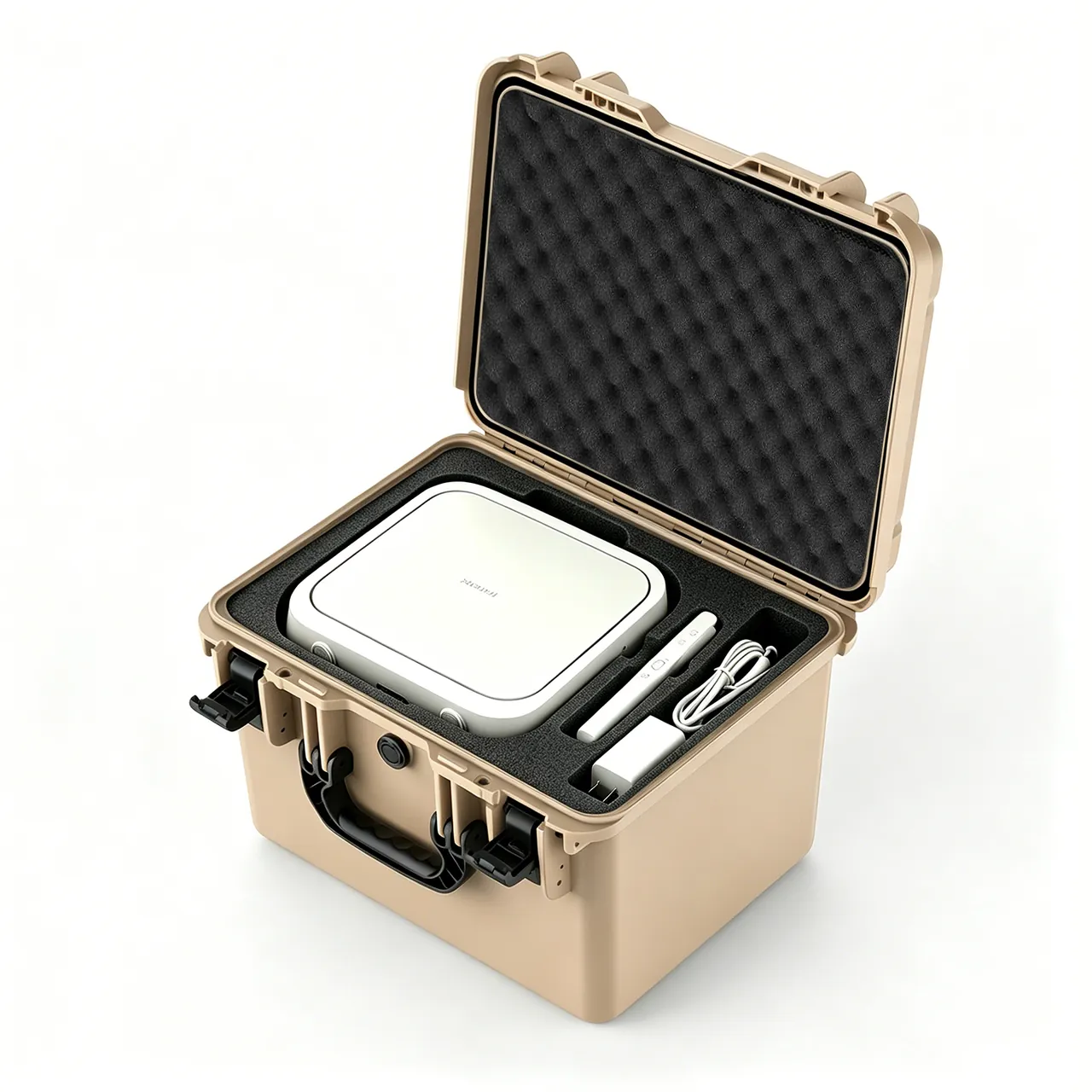
The packaging objective therefore reduces to one sentence: the lens must never experience contact. Every load the lens sees in transit must be carried by the barrel shell, a soft liner inside the barrel wall, and the external compartment foam. JUNZHIJIA ships the welding head as an assembly with the lens already seated in its barrel; closed-cell foam wraps the barrel at 8-12 mm and presses only on the outer cylindrical surface, never on the optic. Assembly-level encapsulation beats bagging the lens alone, because the lens never sees airborne dust at all.
Protective Window Replacement Intervals and Contamination Grading
The protective window is the outermost optic in a welding head and the only component deliberately designed to be destroyed. Its grading logic differs completely from that of the focusing lens. Since the window is a consumable, grading exists not to repair it but to decide when swapping it neither wastes money nor burns extra workpieces.
Grading normally runs along two tracks, visual and metrological:
| Grading method | Procedure | Acceptance criterion |
|---|---|---|
| --- | --- | --- |
| Visual inspection | Oblique strong light, inspect the reflection image | Any fixed non-moving dark spot means replace |
| Transmission check | Hold the window against the source and view transmitted light | Even transmission with no cloud patches |
| Spot test | Fire low power at a workpiece | Focus shows no black dots and no tailing |
| Elapsed-hour method | Log cumulative operating hours | Replace every 8-40 hours depending on dust load |
The elapsed-hour range is wide because duty cycles differ so much. Aluminium welding produces little oxide scale and little fume, so a window can last tens of hours. Stainless steel ground parts throw molten spatter that lays down a speckled metal layer on the window within seconds; that layer absorbs heavily at 1064 nm, heats locally under the beam and can burn straight through the window in minutes.
There is a reverse risk worth naming. Over-protection is also dangerous. Fitting a thicker window to make it "more durable" shifts the focal position, and whether the window is plano-convex or plano-concave, plus its refractive index, decides which way focus moves. An unmatched window can cut penetration depth by more than 20%, and operators typically blame insufficient power and raise the setting, which raises spatter and destroys the window faster. The packaging contribution here is to ship the window specification, transmission, thickness and refractive index in a separate labelled bag so no wrong part is fitted at commissioning.
How Galvanometer Flyback and Jitter Destroy a Weld Path
A scanning galvanometer consists of X and Y torque motors, encoders, driver boards and two scan windows. Its job is to steer the beam along the seam, so path accuracy equals weld accuracy. The two damage types that are hardest to recover after transport are flyback error and jitter.
Flyback is the return stroke after the mirror reaches a hard end stop. A rigid impact can shift the relationship between the mechanical stop and the driver board soft limit, producing a zero offset where the weld start and end no longer coincide; on a 300 mm rectangular seam the two ends miss each other by 0.3-1 mm. Field calibration usually recovers this, provided beam quality is still intact.
Jitter is far more serious. It comes from increased bearing clearance, contaminated encoder discs, or a current loop whose tuning was altered by physical damage, and no amount of software calibration removes it; only a bearing or driver board change does.
| Symptom | Field observation | Root cause | Field repair possible |
|---|---|---|---|
| --- | --- | --- | --- |
| Start and end offset by 0.1-1 mm | First and last spot do not coincide | Zero offset | Yes, recalibrate |
| High-frequency sawtooth in path | Fish-scale weld surface | Jitter from bearing or encoder | No, part replacement |
| Focal drift as focal length changes | Focal plane shifts with angle | Scan window distortion or loose mount | No, re-mount and retest |
| One axis unresponsive | Missing scan line | Driver board or motor failure | No, part replacement |
The cleanest way to separate jitter from offset is a spot test: fire a row of evenly spaced dots on the workpiece and measure spacing and straightness with calipers. Regular sawtooth deviation means jitter; a uniformly tilted pattern means zero offset. For the optical module sitting upstream of the galvanometer, see fiber laser source transport requirements.
Shock Margin of Galvanometer Motor Bearings in Transit
Galvanometer motors come in two common forms, voice coil motors and limited-angle torque motors, and internally they contain magnets, coils, bearings or flexures, and an encoder disc. Transit shock harms them in two distinct ways.
- Direct damage on hard landings. During a drop the rotor strikes a mechanical stop, and the stop edge can chip a magnet or displace an encoder disc. This failure is probabilistic: passing a 0.5 g package test does not guarantee a hundred percent yield, and in practice one unit in three to five shows the defect.
- Cumulative clearance growth. More common is micro-indentation in the bearing raceway. Nothing looks wrong immediately after transport, but a few thousand operating hours later the clearance opens up as temperature rises and jitter appears.
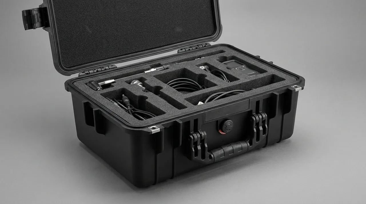
How much margin exists? Galvanometer driver boards normally operate below 80% of rated current, leaving roughly 20% of torque headroom for acceleration and load fluctuation. Packaging should aim to keep the equivalent acceleration transmitted to the galvanometer mounting face inside the safe boundary of that headroom. Three layers are typically used: a rigid inner bay for the galvanometer alone, never sharing foam with large parts; low-frequency foam (EPE or low-density PE) at the bottom to absorb low-frequency energy; and a deliberate stop gap between the inner bay and the case wall rather than a tight fit.
Note the inverted logic of resonance. Hard metal parts fear high-frequency shock, so their protection must be rigid; optical parts fear low-frequency resonance, so theirs must be soft and heavily damped. One foam layer rarely serves both, which is the technical root of the rule that optical components get their own compartment.
Welding Head Barrel Coaxiality and Compartment Support
A welding head comprises a barrel, a focusing lens group, a nozzle, a shield, a gas flow meter and water cooling connections. The most commonly overlooked failure in transit is coaxiality drift: a collision tilts the barrel by 0.2-0.5 degrees, so the optical axis and the nozzle axis no longer coincide and the focal point leaves the weld line.
The consequences are concrete. A focal point off the seam center lowers energy density in the pool center while raising edge spatter, and the heated nozzle can glow locally, degrading the gas shield and the nozzle itself. Field symptoms read as "deep on one side of the weld, shallow on the other" or "heavy spatter wherever the seam turns a corner."
| Support method | How it works | Coaxiality retention | Best for |
|---|---|---|---|
| --- | --- | --- | --- |
| Full clamp band | Band grips the barrel outer diameter | Good, but uneven band force can tilt it back | Flanged heavy barrels |
| Compartment floor cradle | Floor foam supports the nozzle end, rear foam supports the barrel rear | Good, two-point location | Most welding heads |
| Individually suspended parts | Each part bagged and suspended | Best, but assembly becomes awkward | Small parts and lenses |
| Contoured one-piece liner | Single EVA or EPE block cut to the profile | Good and reusable | Volume orders |
Once the focusing lens is installed the cradle location becomes critical: support the barrel at a reinforcing ring or flange, never at the middle of a thin wall. A thin wall held under compression for a long period springs back on release, changing the fit clearance between the lens group and the barrel.
The same cradle logic appears in laser cutting machine optical head protection, which is a useful comparison when both heads ship in one consignment.
Minimum Bend Radius Limits for Beam Delivery Cables
The run from the fiber laser to the galvanometer, and from the galvanometer to the welding head, is an armored cable or a beam delivery tube. It is also the brittle extension of the optical train: once the sheath is compressed until the bend radius falls below its rating, the fiber core can suffer macro-bend loss and lifetime damage, showing up as a slow decline in output power and unstable mode quality.
Packaging constraints follow directly from that:
- Bend radius. The minimum dynamic bend radius varies with diameter and usually falls in the 100-300 mm range. A cable should coil in a natural flat coil with no twist, never in a figure-eight, which imposes a permanent helical stress.
- Connector ends. A single grain of dust on an FC/APC, LC or QBH connector end face can cut coupling efficiency by several percentage points, and an APC angle deviation above 0.5 degrees produces noticeable return loss. Connectors get their protective caps on before entering the bay.
- Position relative to the galvanometer. The cable is fixed by dedicated clips inside the bay and must never hang off the welding head or the galvanometer, because those two parts move in different directions during a drop and a cable bridged between them will be flexed repeatedly.
- Pneumatic and water lines differ. The coaxial air line and the cooling water line are secured separately, since thin-walled cooling hose kinks easily; once flattened, reduced flow raises barrel temperature.
When a cable is coiled into the round space available in a case, use soft ties in a pattern other than a figure-eight, and draw the coil path on the interior so the field team can restore it exactly.
Blocking Class 4 Laser Beams and Fire Safety in Transit
The beam leaving a welding head is Class 4, typically 500-3000 W, focusable and dangerous to look into. Two hazards must be handled during transport.
The first is inadvertent beam escape. If an operator opens the case without first shutting down the source and blocking the aperture, the residual optical path inside the packaging - the lens still seated in its barrel - turns a single misfire into a collimated high-intensity beam confined inside a box. Every optical transport package must therefore include aperture blocking plugs: non-reflective, hard to dislodge, single-use plugs fixed to the inner case wall beside the welding head, and listed on the packing list as a must-install-before-commissioning item.
The second hazard is fire. A Class 4 beam reflected diffusely off metal carries enough energy density to ignite packaging. The arithmetic is roughly this: a 500 W beam at one metre delivers about 40 W/m², well above the ignition threshold of most plastics. The realistic risk is not sea transport but long commissioning sessions with the case parked beside the equipment. Two design responses follow. First, the case material itself is flame retardant, with PC or ABS selected to a UL94 V-2 or equivalent GB8624 rating. Second, no combustible buffer material sits anywhere on a possible beam path; paper partitions, foam and desiccant packs are kept clear of the optical axis.
These rules are invisible at the packing bench and extremely expensive when violated. JUNZHIJIA therefore writes the sequence plug-install, power-down, cavity depressurization as three fixed lines in the packing documentation and asks the customer to sign the commissioning record. For cleanliness requirements around the source and its optical module, see cleanroom equipment and filter case protection.
Condensation on Coated Optics and Constant Humidity Control
Dielectric multilayer coatings are far more humidity sensitive than the glass substrate beneath them. On a long sea voyage or a seasonal crossing, if the case temperature cycles from cool low-humidity nights to warm days, relative humidity on the lens surface can reach condensation.
Condensation damage is not simply water. It is water plus residual cleaning agent plus polishing wax, and the mixture cures into a haze that only a recoating line can remove. Three parallel measures are required.
- Barrier choice. Coated parts ship in aluminium laminate bags evacuated to below 50 kPa with molecular sieve desiccant (3A or 4A type, indicating at 10% RH), heat-sealed. Where nitrogen purging is used, residual oxygen and dew point are recorded together.
- Humidity buffering. The bay carries desiccant dosed from cavity volume and expected dwell time, plus a humidity indicator card. Read the card before deciding whether to dry the contents before opening.
- Ramp rate control. A sea container may swing from 5°C at night to 45°C by day. A fast warm-up expands cavity air and collapses relative humidity; the real danger then is not moisture but outgassing, as foam and plastics release volatiles that deposit on optics. High-grade coated parts should not share a bay with newly blown EPE; use fully aged closed-cell material and assess odor and volatile content after curing.
Compartments also deserve independent sealing. A galvanometer bay with motors and harnesses tolerates slightly higher humidity, while an optical bay should hold its own low-humidity envelope, because a shared case body does not have to imply a shared environment.
Nozzle Tip Carbon Build-Up and Workpiece Oil Residue
The least optical component on a welding head is the nozzle tip. It is a consumable, yet its condition on arrival directly affects the customer's first trial weld.
| Workpiece material | Surface condition | Primary problem | Weld consequence |
|---|---|---|---|
| --- | --- | --- | --- |
| Stainless steel | Ground residual oxide scale | Low-melting scale floats out with shallow penetration | Porosity, inclusions, lower strength |
| Aluminium | Oil film and oxide layer | Oil burns to vapor, forming pores | Lack of fusion, spiking spatter |
| Carbon steel | Rust and mill scale | Unstable arc in gas welding | Irregular pool |
| Galvanized sheet | Zinc melts at 419°C | Vapor explosion and porosity | Wide penetration variation |
The key point is that this contamination is coupled to the welding head. Carbon smoke from burning oil quickly settles on the nozzle, barrel exterior and protective window, and that deposit in turn makes the next weld's spatter stick harder to the equipment. Packaging must therefore consider whether workpieces ship at all.
If samples or trial plates ship in the case, they should be sealed in their own bag with desiccant, kept away from the optical bay so oil mist and oxide flakes cannot be carried into it by air movement; stored upright on a support so broad foam contact does not distort them; and accompanied by cleaning instructions covering method, water quality and drying, so the customer understands that the trial plate must be cleaned to bright metal first.
Wrap the nozzle itself in a lint-free paper or a clean bag. Do not leave it sitting loose in a foam cutout, because the tolerance of a foam hole is usually larger than the nozzle diameter tolerance and the part can strike the hole edge during a drop.
Optical Shock Compartments and Individual Lens Sealing
Everything above reduces to one layout principle: within a single case, optical parts, the galvanometer, beam delivery cable, fixtures and workpieces occupy separate compartments, and no compartment may be stacked on another.
Non-stacking means no large part may rest on an optical part, even when the upper part is heavy but uneven. The reason is that the load is sustained, and long-term foam compression changes the barrel support condition described earlier, so coaxiality drifts; during a drop, any lateral slip of the upper load transfers energy straight through the compartment wall into the barrel.
A workable arrangement places fixtures, the cable coil and pneumatic and water hoses on the top layer, with no optical parts and no precision faces. The middle layer holds one bay per welding head assembly and a dedicated bay for the galvanometer assembly. The bottom layer carries the laser source module, a heavy item that belongs on the case floor, plus soft void fill. Workpieces occupy a side bay in their own bag, never sharing a bag with optical items.
Each bay uses a floor cradle, lateral restraint and a soft top compression, three faces in contact and one face left open, or a very shallow top imprint, so a drop first crushes the foam and only then loads the optic. Closed-cell thickness is back-calculated from the allowable acceleration and allowable crush; a common mapping uses 25-40 mm of medium-density closed-cell foam where 30 g is allowed, and 40-60 mm plus a low-frequency damping layer at the floor where 15 g is allowed and a second drop is possible.
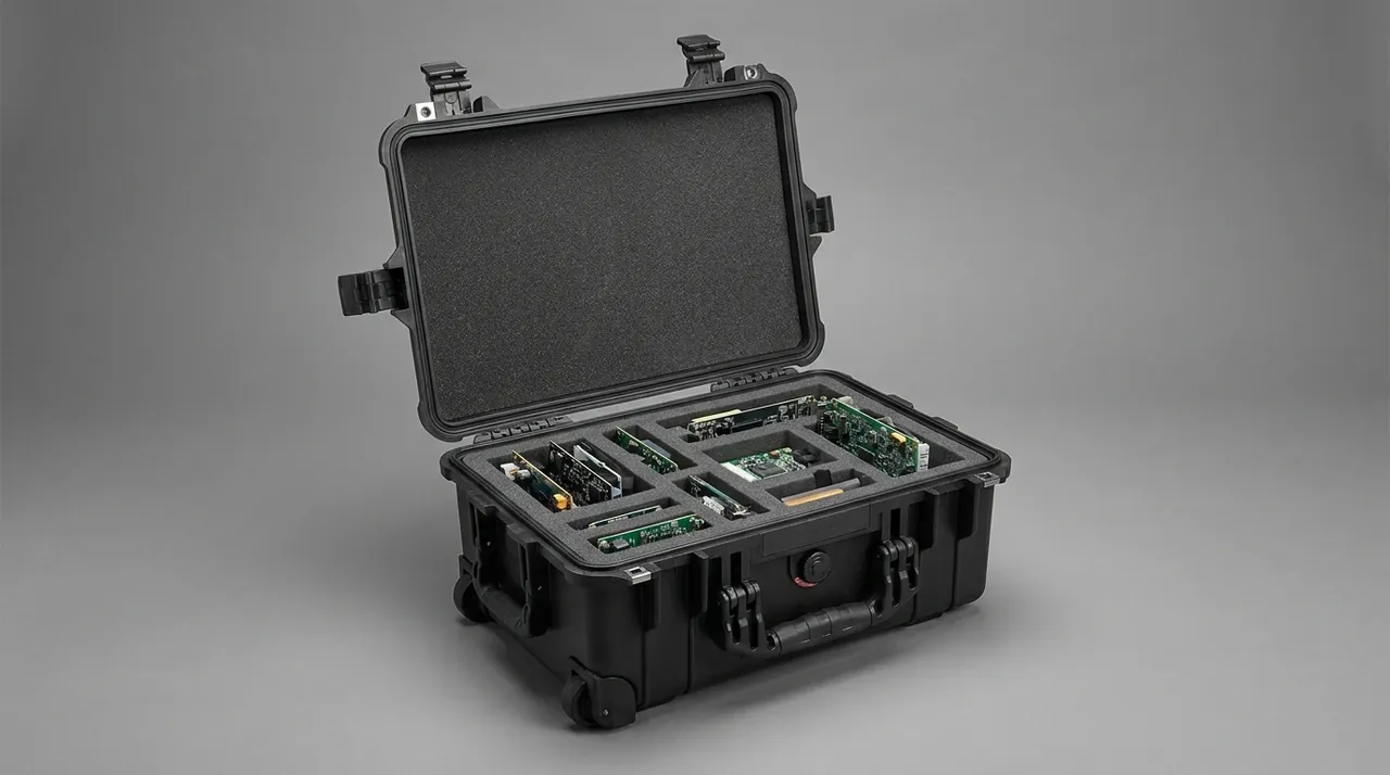
Precut liner options are compared in pre-cut foam insert advantages and use cases, and the fully contoured route in custom foam insert fabrication.
Inbound Acceptance: Scratches, Fingerprints and Spot Testing
Acceptance for optical shipments cannot stop at whether the case is dented. JUNZHIJIA ships a defined sequence in the packing documents, and each step produces a recordable result.
Step one, case condition and lock engagement. Inspect the shell for dents, cracks, distorted latches and misaligned hinges; check that gasket beads are not extruded or rolled, and that the pressure equalization valve membrane is intact.
Step two, humidity card, before opening anything. If the card was applied reversed at packing time, with the high-humidity end facing the dry side, the reading is void and packing photographs should be requested.
Step three, count against the packing list. Order: desiccant pack, aperture plugs, barrel sealed bags, welding head assembly, galvanometer assembly, cable coil, upper harness and workpieces. Lenses are not counted separately, since they stay inside the barrels.
Step four, lens visual inspection. In a reasonably clean area, examine focusing and protective lenses by oblique strong light and by transmission. No fixed dark spot, no scratch and no fingerprint haze means pass on appearance. A fixed spot that does not affect transmission uniformity is logged as pending spot-test verdict. Any scratch is logged with position, length and photographs as transport liability evidence. Any fingerprint or haze means reject for refurbishment; "it still works" is not accepted.
Step five, spot test. Mount the welding head, fire the lowest power at the workpiece, and measure:
| Metric | Method | Acceptance criterion |
|---|---|---|
| --- | --- | --- |
| Focal position | Spot center against crosshair | Within 0.1 mm |
| Focal shape | Edge contour | Near circular, no visible tail |
| Spot repeatability | 20 shots on one command | Position deviation within 0.05 mm |
| Galvanometer path | Fire a rectangle, check edge straightness | Within 0.1 mm |
| Protective window | Inspect the spot area | No black dots, no burn-through |
Step six, galvanometer calibration. Zero calibration first, then rectangle straightness, then a 30-minute continuous run logging focal drift. Visible drift points to a scan window or mounting problem and forces a re-mount.
Step seven, record and feed back. Send results, case photographs and humidity readings back as a signed acceptance sheet, closing the loop. Acceptance criteria and sampling schemes are covered in custom case acceptance standards and AQL, and the instrumentation-side logic parallels precision instrument protective case shock and protection.
JUNZHIJIA Customization: Molds, Compartments and Packing Documents
Every measure discussed here resolves into one case design developed for a specific consignment. JUNZHIJIA confirms the technical inputs with the customer, typically covering:
- Equipment list and split boundary. Which items ship and which stay on site, and whether the focusing lens is already installed, which decides between assembly-level encapsulation and lens-level compartments.
- Optical component schedule. Clear aperture, focal length, coating type (anti-reflective, high reflective, dichroic), and whether a diamond-like hard coat is applied, plus protective window thickness and refractive index.
- Logistics conditions. Sea, air or road; expected duration; temperature and humidity exposure; drop and stacking risk level; number of transshipments. Vibration and resonance analysis is discussed in case vibration testing and transport resonance.
- Opening and handling constraints. Whether lenses must be replaced in the field, whether operators wear powder-free gloves, and whether a bare-lens inspection window is needed.
- Documents and markings. Case number, part number, net and gross weight, maximum stacking layers, center of gravity, lifting points. Test conditions and acceptance criteria go into the purchase technical agreement, where the sequence may follow ISTA packaged-product performance testing, the GB/T 4857 series or ASTM D4169 distributed-cycle practice, chosen from the real route rather than a generic template.
The design output covers case dimensions and opening direction, a compartment layout drawing, foam material and thickness per bay, latch and hinge specification, sealing and pressure equalization strategy, and the packing document index. That index includes the packing list, unpacking sequence, plug installation instructions, the initial humidity card reading, lens inspection guidance, the spot test procedure, drying instructions and acceptance criteria.
External markings follow GB/T 191 and GB/T 13384, with a basic set covering this side up, keep dry, do not roll, maximum stacking layers, plus case number and center-of-gravity marks, applied so they are durable and hard to alter without damaging the case. Both sides should use one numbering logic so the customer can count goods in at destination.
Final protective capability should be demonstrated by transport testing rather than asserted by parameter. For stacking, the case floor needs a load beam or a mating pallet so heavy items transfer through the base into the vehicle load path instead of through side walls and corner fittings. A practical recommendation is to run a 3-5 unit pilot build and pull real data - lens photographs, humidity readings, arrival spot tests - back into the production design before the full batch ships.
Frequently Asked Questions FAQ
Q: The focusing lens is already installed inside the welding head barrel, so is extra sealing still necessary?
A: Yes, but what you seal is the environment around the barrel, not the lens surface. Even with the lens seated inside, three contamination paths stay open. Dust in the cavity can enter the optical path through the focus adjustment thread clearance and through screw holes. When the barrel moves inside its bay, the clearance between lens and barrel wall is squeezed repeatedly and produces a pumping effect that draws cavity moisture and particles toward the optic. After a full-case drop the barrel-to-wall clearance changes abruptly and the lens sees an impact. The correct approach is a clean enclosure for the welding head assembly, an aluminium laminate or clean bag combined with a closed-cell foam cradle, rather than a separate sleeve for the lens, because bagging the lens alone forces you to open the barrel and disassembly is itself a risk source. Desiccant and a humidity indicator card belong in the bay to control dew point. Where the field must swap lenses frequently, spare lenses should be vacuum packed separately with transmission and coating type marked, because mixing coating types changes focus quality outright.
Q: Can a single 5μm dust particle really cost thirty percent of output power?
A: Under specific conditions, yes, but the claim needs qualifying. Focal spot energy density is extremely high, so a 5μm particle inside the clear aperture diffracts and scatters part of the energy while creating a diffraction ring in the focal plane, which lowers the central peak and enlarges the spot. Most of the widely quoted 30-40% figures actually describe fingerprint oil films or metal chips, which cover more area or block the aperture outright, rather than a single airborne particle; for dust the typical effective loss is 3-10%. The numbers vary because contaminant cross-section, position inside or outside the beam, transmission and absorption behavior, and the evaluation method, whether a power meter or a beam profile analysis, all differ. Judge the result on the spot test and focal shape instead of on meter readings. A spot whose central peak has been flattened may register only a small drop on a power meter while penetration depth has already changed on the workpiece. Cleaning advice for handling cases between jobs is covered in protective case cleaning and maintenance.
Q: The galvanometer arrives with weld starts and ends that do not line up. Can the customer fix it in the field?
A: This is usually a zero offset, and it is normally recoverable on site once you separate it from jitter with a spot test. Fire a 200-300 mm straight line and a rectangle on the workpiece and measure the points with calipers. If the pattern is a regular tilt or a start-to-end mismatch while the spacing between consecutive points stays uniform, you have zero offset or angle calibration error, and re-running zero and angle calibration restores it. If the points show high-frequency sawtooth with irregular jitter at the edges, that is jitter from increased bearing clearance, a contaminated encoder disc or a damaged driver board, and software calibration cannot remove it; parts must be replaced. Field recalibration is recommended after transport because bearing micro-indentation often stays invisible until temperature rises after several thousand hours, so acceptance should add a 30-minute continuous run with focal drift logged to expose early jitter trends. Keep the encoder disc clean and the driver board dry during that run, since condensation is a second cause of jitter that is much cheaper to fix than a motor.
Q: Should the case for a Class 4 laser welding head include desiccant and aperture plugs?
A: Both belong there, for different reasons that cannot substitute for each other. Desiccant and a humidity card manage condensation and outgassing, since coated optics are sensitive to water vapor and volatiles that condense when case temperature swings day to night and then cure into haze that only a coating line can polish out. Plugs manage beam escape, because with the lens still seated the residual optical path is intact and one misfire creates a collimated high-intensity beam inside the case, whose diffuse reflection off metal can ignite packaging. Plugs should be non-reflective, hard to dislodge, single-use items fixed to the inner case wall beside the head and listed separately on the packing list as a must-install item. The case material should also meet a flame rating such as UL94 V-2 or the equivalent GB8624 class, and no combustible material may sit on a possible beam path. Write both as separate numbered steps in the unpacking sequence rather than a single line about being careful, and note that the humidity card is only meaningful if it was applied in the correct orientation at packing.
Q: Can the welding head and the laser source module ship together in one case?
A: They may share an outer case, but they must not share a foam layer, and nothing may rest on anything else. The source module is the heavy item and has the largest inertia in transit, so it belongs on the case floor or a mating pallet, transferring load into the vehicle load path instead of through side walls and corner fittings. Put an independent partition and buffer between the optical bay and the source bay, because their failure modes differ: the source module fears vibration and shock through its internal optical path and cooling loop, while optical parts fear resonance and contamination on their coating and focusing mechanism, and one foam layer rarely serves both well. For long sea routes, consider shipping the source module and the optics as two separate consignments with humidity and drop risk managed independently, so one moisture event at a single transshipment point cannot destroy an entire optical train at once. Assembly and disassembly order should be shown with diagrams in the packing documents, and each bay should carry its own humidity indicator so both environments can be read independently on arrival.
Q: Is wrapping coated lenses in EPE foam acceptable?
A: Generally not, especially for high-grade coated parts and any barrel with an open structure. EPE expanded foam works well as a primary shock layer, but its closed-cell ratio and surface cleanliness are unsuitable for an optical bay. It sheds fragments with age and heat, and those fragments land near the optics. Its surface is rough and soft, so wrapping it provides no guarantee of non-contact with a coating; any pressure point transmits straight through into a scratch or indentation. Some EPE formulations also contain plasticizers and blowing residues that volatilize at temperature and deposit as adsorbed contamination on the optic. Use low-density PE, EVA or XPE closed-cell foam for the structural layer, aluminum laminate bags, clean bags or lint-free cloth for the cleanliness layer, and add a closed-cell ring around the barrel so the foam presses only on the outer cylindrical surface. A broader comparison of liner materials appears in custom foam insert fabrication. As a working rule, any material that sheds or outgasses belongs in the vibration bay, never in a bay whose contents are finished optics.
Q: The protective window arrives dirty. Is that transport damage?
A: Separate transport damage from commissioning contamination, because the liability differs. Work backwards on the timeline. If fixed dark spots, haze or a speckled metal layer are visible at unboxing while the packing photographs show a clear window, it is transport liability. If the window is clear at unboxing and spots appear only after powered spot testing, the cause is spatter and handling during commissioning, and the usual parameter-side contributors are workpieces not cleaned to bright metal, a protective window mismatched to the focusing system, excessive power, or insufficient gas shielding. The design contribution is to ship the window specification, including transmission, thickness and refractive index, as a separate labelled bag so the wrong part cannot be fitted, and to state in the documents that the trial workpiece must be cleaned to bright metal and that windows are replaced on a recommended hour interval. Agreeing responsibility before delivery settles the argument faster than debating it afterwards. Photographic records taken at packing are the single most useful piece of evidence in either direction, so the case file should include them.
Q: If an ISTA transport test has already been run, are drop and stacking tests still necessary?
A: That depends on the test objective and how the purchase technical agreement is written. ISTA packaged-product performance testing represents a combined real logistics scenario in which vibration, impact, drop and stacking appear in a sequence; the GB/T 4857 series covers vibration, impact, stacking and drop separately; ASTM D4169 distributes several sequences by expected cycle. The division of purpose is that a packaged-product performance test asks whether the case as a whole survives a realistic logistics run, while individual tests confirm whether a specific failure mode is covered, such as drop exposure on the optical bay or stacking load on the case floor. The essential requirement is that conditions, including item, severity level and acceptance criteria, are written into the purchase technical agreement, and that criteria go beyond the case staying intact to include no content displacement, no visible scratches on optics, seals intact and humidity cards within limits. Running an ISTA test without defining criteria leaves you unable to answer the specific question of whether a scratched lens counts as damage.
Conclusion and Related Reading
Welding head and galvanometer protection translates what optical surfaces fear into case layout. JUNZHIJIA supplies custom molds, closed-cell compartment liners, vacuum sealing and packing documents so the box arrives with an executable unpacking sequence and objective acceptance criteria.
Related Reading