

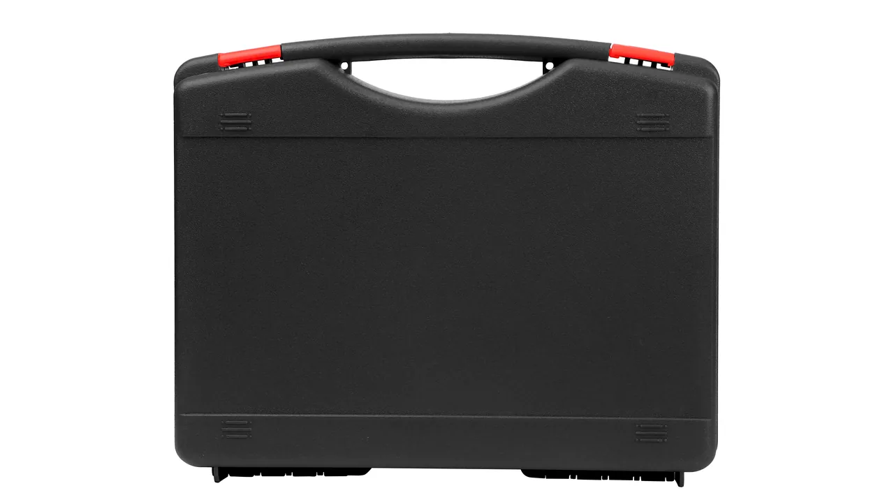
A marine deck crane travels from a shipyard quay to a conversion berth or an overseas delivery point by a route unlike inland heavy haulage. The jib arm is often too long to stand upright, so it moves horizontally or is sectioned into pieces. The slew platform arrives complete with its slewing bearing ring, hydraulic circuits and the upper/lower slew joint, the gear flank bare and traces of the shipowner's last overhaul grease still on the deck plate. Such parts routinely sit in an open port yard, and the interval between delivery and loading is frequently the tropical wet season, where salt, ultraviolet radiation and high humidity act at once. A few months of that is enough to pit the tooth flanks, grow a rust bloom on a bare piston rod, and salt out the internal passages of a hydraulic quick coupling.
The real objective is not to stuff the parts into a crate; it is to guarantee that a slew platform and a jib arm carry no dissolvable salt, no trapped moisture, no working load and no loose hardware through the yard, across the deck and through a long sea voyage. JUNZHIJIA builds the marine deck crane case as an anatomy-led packaging system around those two components: a dedicated annular chamber for the gear ring, anti-loss compartments for pins, separated cradles for the cylinder barrel and the chrome rod, and dedicated supports with end-of-part cushioning for sectioned long members.
Table of Contents
- Salt Spray, UV and Humidity: the Triple Corrosion Path on Deck Steel
- Sea Water Residue on Slewing Ring Teeth and Flank Acceptance
- Sealing the Upper and Lower Slew Joint and Hydraulic Port Capping
- Jib Pin Anti-Rust and Anti-Loss Compartments by Node Position
- Luffing Cylinder Chrome Rod Protection and Residual Oil Management
- Hook Block Latch and Sheave Groove Dehydration Before Boxing
- Overlength Jib Sectioning Points and Tip Deflection Restraint
- Class-Society Traceability Requirements for Crated Crane Parts
- Mooring Surge Load Restraint and Hull Sway Cushion Creep
- Scratch Touch-Up Grades and Wet Film Thickness Verification
- Harbour Sulphide and Dust Loading on Case Outer Skins
- Stacking, Drop and Vibration Verification for the Crated Slew Platform
- Arrival Acceptance: Flank Grading, Pin Count and Document Sign-Off
Salt Spray, UV and Humidity: the Triple Corrosion Path on Deck Steel
A deck crane works in the open on the fore or aft deck, so its corrosion environment couples three factors rather than any one of them, and the liner has to answer all three at once.
| Aggressive factor | Trigger condition | Appearance on the slew platform | Appearance on the jib arm |
|---|---|---|---|
| --- | --- | --- | --- |
| Chloride deposition | Salt-bearing port air settles on unrinsed steel | Blistering beside welds, coating delamination at edges | Rust weeping from the inner fillet of lattice gusset plates |
| Ultraviolet radiation | Long exposure of coating and seals | Epoxy topcoat chalks and loses gloss, gaskets harden | External anticorrosion coating fades and microcracks |
| High humidity | Diurnal cycling turns salt into an electrolyte film | Rust points and persistent water film on the tooth flank | Corrosion inside pin bores, leading to stiffness |
| Condensation cycling | Night cooling produces sweat inside the enclosure | Water beads on inner walls, accelerating case corrosion | Absorbed liner moisture overnight after crating |
The paths couple in a specific way: salt supplies the electrolyte, humidity supplies the conductive path, ultraviolet destroys coating and seals. Together they do not add, they multiply. Sealing the crate addresses only one path, and if salt residue or old grease remains against a gear flank or inside a pin bore, closing the crate creates a sealed high-humidity microclimate where corrosion accelerates.
JUNZHIJIA treats salt removal as a precondition for sealing. The slew platform is flushed with high-pressure fresh water before crating, concentrating on the tooth flanks, ground weld zones and hydraulic hose connections. Jib pins are wiped one by one to bright metal before protective fitting, leaving neither grease film nor salt bloom. Drying takes place under a covered shelter, because wind drying outdoors simply redeposits fresh salt particles.
Liner materials follow the same logic. The outer barrier layer resists salt and ultraviolet; the liner facing the metal controls moisture and breaks the condensation path. A common build pairs a flame-retardant fabric outer skin with EPE foam cushioning, and swaps the contact face against the gear ring and pins to closed-cell IXPE. Salt spray testing to GB/T 10125 or ASTM B117 runs on coupons cut from that exact combination, not from bare plate.
Sea Water Residue on Slewing Ring Teeth and Flank Acceptance
The slewing bearing ring is the most vulnerable component in transit: a thin-walled ring several metres across, with carburised or induction hardened tooth flanks. Because the hardened layer and the parent metal behave very differently, rust there does not stay cosmetic. Isolated points become pitting, and pitting becomes spalling and transmission noise the moment the ring drives the pinion.
The handling sequence before sea transport is fixed:
- Disassembly and cleaning. If the platform left the factory assembled, the flanks still carry a protective grease film. Dissolve it with solvent to expose bare metal, then rinse with fresh water and blow off with compressed air.
- Temporary coating. Within four hours of cleaning, apply a removable corrosion inhibitor or an aerosol short-term protective agent. Film thickness is not the objective; complete coverage is, particularly the tooth tip, the flank and the root fillet radius.
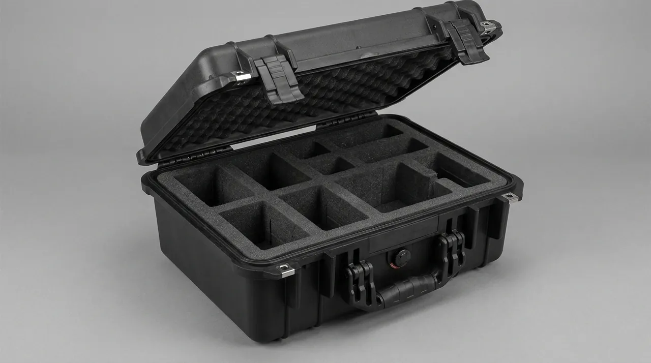
- A dedicated annular chamber. The ring goes into its own corrugated annular carton or annular cushion sleeve, then is strapped to the platform frame. Internal clearance is held at 15 to 25 mm per side so that, once the cushioning is compressed, the ring neither shifts nor distorts.
- Independent desiccation. One or two 100 g packs of montmorillonite or molecular sieve desiccant go into the annulus, with a humidity indicator card showing directly whether the relative humidity inside has exceeded 40%.
Arrival acceptance works to graded limits:
| Inspection item | Criterion | Disposition |
|---|---|---|
| --- | --- | --- |
| Rust points on the flank | Isolated spots up to 0.5 mm, no more than two per 10 cm of tooth length | Accept, treat each spot with inhibitor oil |
| Pitting on the flank | Any crater larger than 0.5 mm | Reject, refer to the shipowner and repair yard |
| Carburised layer spalling | Any visible flake lifting | Reject, treat as transit damage for the claim process |
| Radial distortion | Roundness deviation beyond drawing tolerance | Reject, re-round and re-inspect |
| Flank cleanliness | Residual grease or oily contamination | Return for cleaning and re-coating |
One procedural detail matters more than the rest. Flank inspection must be completed within two hours of opening, before interior and exterior environments equalise. Opening breaks the controlled dry interior, and moisture in the annulus condenses onto the flank as temperature equalises, so rust points recorded afterwards may never have existed. Photograph the flank inside the case first, then open section by section, inspecting and treating one section before moving on. The same logic governs precision mating surfaces elsewhere, as covered in our guide to bearing and gearbox cases.
Sealing the Upper and Lower Slew Joint and Hydraulic Port Capping
The hydraulic circuits are the other frequently overlooked high-risk item. Between the upper and lower structure sits a slew joint, usually a multi-way rotary distributor or central swivel, carrying oil from the fixed frame to the rotating platform. Left open in transit, its ports take in salt and water, and at reassembly the fresh oil can emulsify, spool valves stick and seal elements corrode.
JUNZHIJIA applies a three-part logic of capping, desiccation and preserved inspection access:
- Port capping. Every external hydraulic interface, including quick couplings, threaded ports and blanking positions, receives a dedicated dust cap with a thread or claw engagement rather than adhesive tape. Tape absorbs moisture in a high-humidity sea voyage and lets go, so it is never the primary seal.
- Chamber separation. The lines and the slew joint occupy their own cushioned chamber, isolated by foam so the weight of the platform structure cannot bear on them. Support spacing along the run does not exceed 800 mm, and longer sections add a flexible lashing strap.
- Desiccant and breather. That chamber carries 50 g of desiccant, and the enclosure is fitted with a micro-positive-pressure breather valve that holds interior humidity below the dew point and prevents condensation across the diurnal swing.
- Preserved inspection window. Sight glasses and level-gauge positions on the slew joint are left visible through a marked window in the case wall, so oil weeping can be confirmed without opening the enclosure.
Classification attention converges on exactly these positions. ABS, DNV and CCS crane examinations require hydraulic tightness verification before the function test, and weeping at a joint or hose end is a routine finding. The documents must therefore include a hydraulic interface schedule listing every port number, capping state and re-inspection requirement after arrival. Comparable residual-media problems in powertrain components are treated the same way, as described for engine valve and valve-train cases.
Jib Pin Anti-Rust and Anti-Loss Compartments by Node Position
The lattice jib relies on grouped pins at its node connections. A pin is small, light enough to jump out under vibration, and its loss prevents the jib from being re-erected at all. Sourcing a replacement takes weeks, which makes it the highest-consequence small part in the package.
The chamber arrangement is fixed by part class:
| Part | Chamber arrangement | Protective measures |
|---|---|---|
| --- | --- | --- |
| Main pins, large diameter | One tubular chamber per pin, bore at pin diameter plus 20 mm | End caps plus desiccant bag plus IXPE facings inside the bore |
| Pin mating hardware | Same chamber as the pin, or an adjacent chamber | Anti-loss circlets on end-plate holes, hardware listed separately |
| Safety pins and cotters | Collected in one small chamber | Bagged separately and placed in the main pin chamber roof so they cannot scatter |
| Stop plates and washers | Paired with the corresponding pin | Paired labels stating the installation position |
Anti-loss protection works in three layers. The first is physical constraint: once the pin is inside, both ends close with locked caps so that even inverting the case cannot eject it. The second is positional labelling: each chamber carries a label reading something like "jib section 3 node main pin x2", reconciling with the packing list and the arrival sheet. The third is a frozen schedule listing quantities item by item, with any shortage raised on the quay during unloading rather than deferred into a dispute after loading.

Corrosion protection concentrates on the pin bore, because the bore forms a closed cavity in which moisture cannot dissipate. JUNZHIJIA coats the bore wall with inhibiting grease before assembly, wraps the pin in waxed anti-rust paper or vapour corrosion inhibiting paper, and slides it into the chamber. The pin body itself is cleaned and coated, with plastic end caps closing both ends. Related long-duration outdoor storage failure modes are catalogued in our drydock equipment cases covering keel blocks and winch components.
Luffing Cylinder Chrome Rod Protection and Residual Oil Management
The luffing cylinder holds the jib at a commanded attitude and consists of a barrel, a piston rod, a sealing set and upper and lower lugs. The chrome layer on the rod is only 0.03 to 0.10 mm thick: hard, but poorly defended against chloride, so the moment it is scratched a pitting site exists. It is the most delicate surface on the machine.
The barrel and the rod are never allowed to share a chamber. The JUNZHIJIA standard arrangement is:
- Barrel. Fixed at both ends with an intermediate stiffener so transport vibration cannot deform the bore entry. Each bore receives a dedicated inner cap with an oil-resistant gasket between cap and barrel.
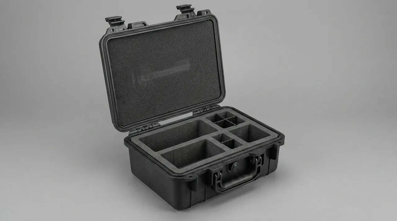
- Piston rod. Its own lined chamber with a 25 to 30 mm cushioning gap all round, filled with EPE foam and restrained by two crossed webbing straps. Additional nylon bands secure the rod head and rod tail against lateral migration.
- No direct contact. The chromed surface never bears directly against a metal part or bare foam. Soft non-woven fabric or PE film is interposed, and any hard block touching the rod is recorded as a non-conformity at packing inspection.
- Hydraulic fluid management. Residual oil is handled in one of three ways depending on the shipowner: nitrogen charge sealing at 0.02 to 0.05 MPa, full dry-nitrogen purge followed by capping, or draining with internal corrosion protection. A nitrogen charge requires a recorded pressure value and a charging date.
Arrival inspection covers four points: examine the reflective rod surface for longitudinal scoring before removing any packaging; measure the thickness differential between plated and unplated areas, or read it with a portable eddy-current gauge, to confirm no corrosive thinning; push the rod through its full stroke by hand and confirm smooth travel, since stiffness is usually the signature of liner debris at the seal face; and check that the nitrogen charge record is still valid. Comparable hydraulic protection in submerged work is treated in our dredging pump cases.
Hook Block Latch and Sheave Groove Dehydration Before Boxing
The hook block is the end effector, comprising the hook body, safety latch, swivel bearing, hoist wire rope and sheave block. Its transit problem is that it looks intact while corroding internally, since the gap under the latch, the swivel raceway and the sheave rope grooves are invisible without disassembly.
The packaging approach is either to disassemble and then protect, or to seal the assembly while preserving inspection access. The choice follows the hook size:
| Approach | Condition | Key measures |
|---|---|---|
| --- | --- | --- |
| Sealed assembly | Hook block complete, latch closed | Mechanical clip over the latch; corrosion inhibitor grease injected into the swivel bearing |
| Component packaging | Hook already disassembled or the bearing replaced | Hook body in its own chamber; latch bagged separately with its orientation marked |
| Wire rope coiled | Rope supplied separately | Keep the original winding direction, clamp the rope end, never reverse the coil |
Sheave groove protection is the priority. If salt residue and old grease remain in the grooves, the hoist rope runs dry and abrasive at commissioning and rope life collapses. The process is to wipe the grooves, rinse with fresh water, blow dry, apply groove-specific corrosion inhibitor grease, then cover the grooves with plastic film so they cannot be recontaminated in transit.
Latch engagement must be checked on arrival. A latch seized by corrosion can spring open during the first lift, a serious safety hazard. Lever it gently with a bar; it must return freely. Where it sticks, use a rust remover and lubricant, and never strike it with a hammer.
Overlength Jib Sectioning Points and Tip Deflection Restraint
Lattice jibs routinely exceed 20 m, and the length required for maximum capacity can pass 30 m. Container dimensions and loading platform capacity conspire against that, so an overlength jib is almost always sectioned, and the sectioning method determines whether the pieces can be re-erected accurately later.
The technical basis for sectioning is the jib deflection curve. Tip deflection under full load is a limit given by the manufacturer, commonly expressed as a percentage of arm length or as an absolute figure depending on the model and the governing rule. Section breaks must fall at lattice node points where bending moment is low, and each piece must stay inside the elastic range while being handled and stored. Typical practice is to break the jib by numbered sections, marking the flange or gusset positions at both ends of every piece.
Packaging requirements for sectioned jibs:
- Fit timber or steel end protectors on both ends of every section so flange edges are not damaged in the stack.
- Place supports at roughly one fifth and four fifths of the section length, avoiding the classic two-point support that leaves the middle of the member hanging and bending.
- Fit removable separators between adjacent sections so they cannot slide against each other, since sliding abrades the gusset coating.
- Touch up the gusset paint immediately after sectioning and let it cure before the package is closed; crating over uncured paint prints the two faces against each other and creates a corrosion initiation site.
- Stack no more than two layers inside the case, keeping the upper layer load clear of gusset plates and diagonals.
Deflection control continues into storage. Sectioned jibs must rest on level sleepers at no more than 2 m centres, on drained ground of adequate bearing capacity. Weak ground lets a section settle slowly, bedding loads unevenly and the coating is crushed open, a damage form easily overlooked during long storage. The same principles govern long linear members, as illustrated by our drilling rig and tool cases.
Class-Society Traceability Requirements for Crated Crane Parts
ABS, DNV and CCS crane examination normally covers a factory inspection and an aboard inspection after loading. Crating and traceability are not themselves imposed rules, but they shape the outcome along two paths. First, if a part arrives corroded, distorted or incomplete so the examination cannot be completed, rework and re-inspection carry heavy berth cost. Second, many shipowners write the arrival condition into the technical contract, converting packaging quality into contractual liability.
JUNZHIJIA therefore builds three-part traceability into the crating documents:
| Traceability element | Documentary expression | Purpose |
|---|---|---|
| --- | --- | --- |
| Part identification | Label on every chamber with part number, drawing number and location code | Fast location at unpacking, no mixing of similar parts |
| Condition record | Signed pre-crate inspection sheet covering cleanliness, coating and capping | Evidences the pre-shipment state and excludes in-transit liability |
| Environmental record | Desiccant mass, nitrogen charge pressure, humidity indicator card | Establishes whether exposure occurred when a claim is assessed |
The document set supporting a survey normally contains crate photographs, with three mandatory shots at the ring lift, the pin insertion and the jib reassembly; material certificates for the case sheet and sealing gasket; the signed inspection sheet; and an unpacking instruction naming the opening order, recommending that sectioned jib crates are opened first, then the pin chambers, then the slew platform case with the ring chamber, so the most precise flank is inspected while the environment is still suitable. The process behind third-party inspection reports is described in our guide to CNAS and CMA test reports.
Mooring Surge Load Restraint and Hull Sway Cushion Creep
Between crating and loading lies a transfer phase whose load profile is unlike road haulage. Hull sway tilts stowed components cyclically with the swell, typically on a 6 to 12 second period, and cyclic loading causes creep in the foam so support force under long stowage decays. Mooring impact delivers a single severe shock when a line tightens as the vessel comes alongside, shifts berth or takes a tow, potentially several times the static weight. Deck vibration enters the structure from main engine and generators as high-frequency low-amplitude motion, loosening fasteners and driving fatigue into welds.
| Risk | Countermeasure | Governing parameter |
|---|---|---|
| --- | --- | --- |
| Creep under cyclic sway | Raise foam density, limit permanent compression to 25% | Supporting foam density not below 35 kg/m3 |
| Mooring impact | Anti-slip mat plus steel strap anchorage to the deck | Two straps on each diagonal of the case |
| Deck vibration | Anti-loosening on fasteners, secondary restraint on pin chambers | Thread compound or spring washers on threaded parts |
| Local impact | Corner protectors on all exposed edges, guard shrouds on exposed ports | Corner protection at every external edge |
A displacement indicator card is also placed inside the case. If foam-to-part clearances show significant gaps at unpacking, the load path exceeded what the design anticipated and the event should be photographed and reported to the supplier immediately. That is more useful than retrospective blame, because it converts an unverifiable impression into a decidable record. General loading precautions are covered in our case shipping loading precautions, and stacking rules in our case warehouse storage rules.
Scratch Touch-Up Grades and Wet Film Thickness Verification
Factory coating here is normally zinc-rich primer plus epoxy iron-oxide intermediate plus epoxy topcoat, with a total dry film thickness of 200 to 400 microns. Every step of sectioning, chamber loading and yard transfer can scratch or chip that film. Such damage passes factory inspection, yet the outcome after a sea voyage depends entirely on whether it was found and treated.
| Damage level | Criterion | Treatment process |
|---|---|---|
| --- | --- | --- |
| Light scratch | Cut penetrates the topcoat only, no substrate visible | Local abrasion, two coats of matching topcoat |
| Moderate scratch | Topcoat and intermediate breached, zinc layer visible | Feathered abrasion, zinc-rich primer plus topcoat |
| Severe scratch | Bright parent metal exposed | Rebuild to the original system, film thickness per specified DFT |
| Edge chipping | Coating crushed at a corner with steel exposed | Abrade the whole facet and recoat entirely, no local repair |
| Wide scratch area but DFT in tolerance | Dry film thickness measurement passes | Local repair permitted, positions recorded |
Timing of film thickness measurement is decisive. Measurement follows cure, and an epoxy system typically needs seven days at 23 C and 50 percent relative humidity. Parts must not be moved during that period, nor enclosed in a sealed chamber, because blocked solvent vapour produces a skin-dry film that has not cured through. Touch-up is therefore done in an open or forced-ventilated area, and the package closed only after cure.
Salt spray testing is valuable for screening materials, not for certifying a finished crate. JUNZHIJIA builds coupons to GB/T 10125 or ASTM B117 from the same materials as the liner, the sealing gasket, the cushioning and the case sheet, and combines them with the case-level test. That keeps the cost controlled and the result reproducible.
Harbour Sulphide and Dust Loading on Case Outer Skins
Port air carries more than salt. Sulfur oxides from diesel handling and ship emissions, heavy aerosols, and dust lifted from a container yard settle on the case and form a highly hygroscopic contamination layer. Sulfides generate sulfurous and sulfuric acid under damp conditions, which sharply accelerates coating and plating failure. The response to this chemical contamination is barrier-first:
- The outer skin prioritises acid and alkali resistance combined with ultraviolet ageing resistance rather than strength alone.
- Sealing gaskets are selected for weather and chemical media resistance together, since sulphide attack hardens and cracks a poor gasket long before the case fails.
- Breather valve diaphragms are chosen in materials insensitive to sulphides, because a valve that fails in a port environment admits the very moisture it was meant to exclude.
- Open yard storage should not exceed three months; beyond that, schedule an unpacking inspection, replace the desiccant and re-check the ring and the pins.
One common misconception is worth naming: higher sealing class is not automatically safer. The dominant risk at sea is not vapour ingress but that salt and contaminants carried into the crate cannot escape again. JUNZHIJIA therefore keeps gas exchange in its mid and high grade solutions, with a breather valve balancing pressure and humidity and desiccant as backstop. That delivers a breathable, observable and recoverable package rather than a dead void.
Stacking, Drop and Vibration Verification for the Crated Slew Platform
Case strength comes from the division of labour between structure and cushioning. The case carries rigidity and the environmental boundary; the foam absorbs impact energy by compressing. Verification is run as a duty matrix against the assembled system of liner plus case, never against a sheet of material on its own.
| Verification item | Method or basis | Criterion |
|---|---|---|
| --- | --- | --- |
| Stacking | GB/T 4857.4, uniform stacking test | Permanent foam compression at the bottom layer at or below 25 percent, no permanent case distortion |
| Drop | GB/T 4857.5 or ISTA 1A, six-face and corner drop | No part displacement beyond tolerance, foam not driven through |
| Vibration | GB/T 4857.7 or ISTA 2A, stacking vibration simulation | Fasteners remain tight, no movement in the ring chamber |
| Transport simulation | ISTA 3A or an equivalent route | External case markings intact, internal state meets the delivery standard |
| Salt spray | GB/T 10125 or ASTM B117, coupon method | No undercutting at the scribe, no blistering |
Four component-specific checks deserve emphasis. Ring chamber migration: after vibration testing, measure axial and radial displacement of the ring in its chamber; it must stay below 3 mm so flanks cannot fret. Pin chamber retention: open after combined vibration and drop testing and count pins and hardware; not one item may be missing. Barrel coaxiality: re-measure both barrel ends after the drop test; the increment must stay inside drawing tolerance, since an offset shows up later as a binding rod. Jib section deflection: measure the permanent increment, to catch sections bent in transit without showing it.
Arrival Acceptance: Flank Grading, Pin Count and Document Sign-Off
Uncrating follows a fixed sequence, and the record made before opening is worth more than any repair afterwards. Inspect the case exterior for damage, water ingress and abnormal rust, photograph all six faces and the seal, then open in the order sectioned jib crates, pin and hardware chambers, hydraulic and cylinder chambers, and finally the slew platform case with its ring chamber, inspecting, photographing and signing for each chamber before opening the next.
Arrival acceptance checklist, each item signed separately:
- Case exterior, seal and shipping marks intact, with the seal number matching the packing list.
- Desiccant mass and indicator card within requirement, with no condensation inside the chamber.
- Tooth flank free of excessive rust points, pitting and carburised layer spalling.
- Pin quantities, specifications and mating hardware checked item by item against the anti-loss schedule, with stop plates and washers complete in pairs.
- Nitrogen charge record still valid for the luffing cylinder, with no corrosive thinning and no longitudinal scoring on the chrome rod.
- Hook latch moving freely, sheave grooves free of corrosion and adhesive residue.
- Jib section count and node numbering complete, gusset touch-up cured, film thickness records present.
- Hydraulic port caps intact with no sign of prying, and the accompanying documents consistent with the technical file list.
JUNZHIJIA supports the custom route from chamber layout drawn to the component drawing, through sample case trial assembly and tooling, to OEM and ODM production, and can output the full document set against shipowner and classification society templates. Where case dimensions are constrained by container internal sizes, the sectioning logic in our aluminum extrusion die cases is worth reviewing; where total case mass approaches the platform limit, the layered weight reduction described for CNC spindle cases applies.
Frequently Asked Questions FAQ
Q: What is the fundamental design difference between slew platform and jib arm cases?
A: The two components fail in opposite ways, so their chamber logic is reversed. The slew platform is block-like and integrated, so the objective is planar protection against salt deposition and abrasion. Its protection is a barrier outer skin, an independently sealed chamber and a full-face cushion liner that spreads load and avoids crushing paint film or welds. The jib arm is linear and needs restraint at many points, so the objective is line support and deflection control. Its weak points are the gusset plates and the pin bores, and a long member risks buckling and migration in transit, so it is split by numbered sections with supports near the fifth and four-fifth points and stacking limited to two layers, keeping gusset plates from rubbing. Dimensionally, the platform case works by face and the jib case works by line; the platform fears dents and scratches, while the jib fears deflection and lost hardware. Neither can be handled by a single generic crate, because the load paths and the corrosion surfaces are entirely different.
Q: What is the basis for sectioning a jib arm, and how are section points chosen?
A: A break must fall at a lattice node where bending moment is low; it can never be made by cutting through a diagonal arbitrarily. Selection proceeds in three steps. First obtain the manufacturer bending moment diagram for the jib under full load and lifting conditions and mark the low-moment zones. Second reconcile that with the case internal dimensions and the loading platform capacity to obtain the permitted single-piece length. Third, subject to that length, prefer standard section-number boundaries, then verify that the permanent deflection of each piece in its own dead-weight resting state stays within the manufacturer's permitted value. Two checks close the exercise. Mark every flange and gusset position at both ends of each piece before separation, because a node identified only after unloading tends to be fitted in the wrong order and hold up reassembly. And key the section map to node numbers in the packing list, so the re-erection team can see which pieces belong together. After cutting, gusset touch-up must be applied and allowed to cure before the package is closed, since closing over uncured paint produces printed impressions between mating faces that become the initiation point for corrosion after loading.
Q: Why can a chrome plated piston rod not simply be wrapped in foam?
A: The plating is only about 0.03 to 0.10 mm thick. It is hard but highly vulnerable to chloride and to hard particles. When foam is compressed or dragged during handling it releases debris and metallic fines into the interface, creating three-body abrasive wear, while the collapsing foam pores press shallow irreversible marks into the rod surface. Three-body abrasion is why a spotless foam wrap still ruins a rod, and why handling is specified with clean nitrile gloves and lint-free cloth rather than bare hands. Both effects are amplified by the first lifting motion after loading and cause early seal lip failure. The correct build interposes soft non-woven fabric or PE film, maintains a 25 to 30 mm cushioning gap on all sides, forbids any hard block from touching the rod, and uses two crossed straps to control lateral migration. Acceptance is by visual inspection of the reflective surface, and any longitudinal score or rough tactile feel is a non-conformity that must be recorded before the crate is closed.
Q: Rust points appear on the ring tooth flank after sea transport. Are they acceptable?
A: They must be judged by size, not accepted or rejected as a whole. Isolated spots up to 0.5 mm, limited to two per 10 cm of tooth length, are normally acceptable; treat each with inhibitor oil and record it before release. The threshold exists because the flank is a hardened friction surface: a shallow point can still be dressed out by the running gear during re-erection, whereas a crater large enough to disturb the contact pattern changes how the pinion loads the flank and how the ring runs on its bearing. Any crater larger than 0.5 mm represents pitting and is not acceptable without an assessment from the shipowner and the repair yard. Flake lifting of the carburised layer is transit damage and goes straight into the claim process. One procedural point dominates all others: inspection must be completed within two hours of opening, before interior and exterior conditions equalise, because opening breaks the controlled dry interior and moisture in the annulus will condense onto the flank, so rust points recorded afterwards may never have been present in the first place.
Q: Do classification societies such as ABS, DNV and CCS impose requirements on the crating itself?
A: Crating is rarely a directly imposed rule, yet it affects outcomes along two paths. The first is survey cost: examinations by ABS, DNV and CCS cover factory and onboard stages, and parts that arrive corroded, distorted or incomplete can block the examination, triggering rework and re-inspection with heavy berth cost. The second is contractual transfer: many shipowners write arrival condition clauses into the technical specification, binding transit damage to packaging quality. The most effective response is to make the crating actively support the survey, so that a surveyor can read the state of a part from the file rather than from the crate. The document set should carry a chamber-by-chamber packing list, a cleanliness and coating record for the ring, a hydraulic port capping schedule, desiccant and nitrogen pressure records, and an unpacking instruction naming the opening order, so a surveyor can begin at any case without unpacking the entire shipment.
Q: Why is a breather valve fitted instead of chasing a hermetic seal?
A: Because the dominant risk at sea is not vapour ingress but the retention of salt and contaminants carried in. An absolutely hermetic void traps whatever salt, sulfide and dust entered during the port yard, forming a highly hygroscopic contamination layer, and diurnal temperature swing can add condensation, combining salt and moisture inside an enclosed volume and accelerating attack on plating and coating. JUNZHIJIA mid and high grade solutions therefore use adjustable breather valves for gas exchange, with 40 percent relative humidity indicator cards to observe chamber condition and desiccant as backstop. The breather does not replace sealing; it complements it, because the valve governs gas exchange rather than liquid droplets, and the gaskets still have to exclude water while the outer skin survives ultraviolet ageing. This yields a breathable, observable and recoverable package rather than a dead void, and avoids over-investing in sealing class alone while leaving the actual contamination pathway unaddressed.
Q: What does long-term outdoor storage of sectioned jib members require?
A: Three points dominate. First, support spacing and ground capacity: sleepers at no more than 2 m centres on level, drained ground of adequate bearing capacity. Weak ground lets a section settle slowly under long stowage, bedding loads unevenly and the anticorrosion coating is crushed open. End sheaths over exposed flanges help in handling but do little for a jib standing for months, because corrosion concentrates where a sleeper cuts into the coating and traps moisture in the joint. Second, stacking direction and count: no more than two layers, with upper layer loads kept clear of gusset plates and diagonals so that a support point never bears on a gusset plate below. Third, scheduled opening: storage beyond three months should trigger unpacking, desiccant replacement, and re-verification of pins and the ring together with a film thickness check on gusset touch-up. Record the storage start date at handover, because it fixes the boundary of responsibility for any later damage.
Q: To what depth must damaged anticorrosive coating be treated in the field?
A: Work in four grades by penetration depth. A light scratch breaks the topcoat only with no substrate visible, so abrade and apply two coats of matching topcoat. A moderate scratch breaks through the topcoat and intermediate to expose the zinc layer, requiring feathered abrasion followed by zinc-rich primer and then topcoat. A severe scratch exposing bright parent metal must be rebuilt to the original system at a specified 200 to 400 micron dry film thickness. Coating crushed at an edge with steel showing is edge chipping: abrade the whole facet and recoat entirely, never patch it locally. The decisive factor is timing. An epoxy system needs about seven days at 23 C and 50 percent relative humidity, must not be moved during that time nor sealed in a closed chamber, because blocked solvent vapour produces skin-dry film that has not cured through. Cure before crating, and record the position of every repair on the acceptance sheet.
Conclusion and Related Reading
Salt removal, capping, chamber separation, anti-loss restraint, touch-up and preserved inspection access are what carry a slew platform and jib arm through sea transport. JUNZHIJIA supports drawing-based chamber design, sample case trials, tooling, OEM and ODM production, and classification society document sets.
Related Reading