


Valve-train components share a distinctive trait. Each part looks small, yet its tolerances are extremely tight and its assembly relationships are highly sensitive. If a valve stem's straightness drifts by only a few micrometres, the guide bore wears unevenly, the valve fails to seat properly and cylinder pressure drops. If a hydraulic lifter's plunger bore is scored or contaminated by a particle, the result can be noise, loss of lash self-adjustment, or a shift in valve timing. The conclusion up front: the point of an engine valve and valve-train case is not how much it holds, but independent location per part, zero damage on contact faces, and controllable particle contamination. Valves must stand in rows and be held by profile-cut locating holes around the stem, lifters and hydraulic parts must sit in individual compartments and keep their factory assembly state, and long shafts such as camshafts and rocker shafts need full-length multi-point support against bending. Specify at least IP65 for the shell, go to IP67 for ocean export and humid regions, manage mating-face particles using ISO 4406 cleanliness thinking, and verify transport under ISTA and GB/T 4857.
What troubles procurement and process engineers most is invisible damage. Valve-train failures are rarely fractures. They are surface degradation: a faint impression on the seat angle face, a slight bend in the stem, a single metal chip against a lifter plunger wall. Installed in an engine, the symptom may be rough idle, scattered cylinder pressures or higher fuel consumption, and diagnosis requires stripping the entire cylinder head. Packaging for these parts must therefore be designed as precision mating-pair protection, not as hardware storage. This article works backwards from failure modes and gives usable guidance on case selection, insert structure, cleanliness control, rust prevention, transport verification and acceptance checklists for engine plants, component suppliers, aftermarket spare-part teams, and procurement and logistics staff.
Table of Contents
- 1. Why Valve and Valve-Train Components Need Dedicated Cases
- 2. Where Valves Fail: Stem Straightness, Seat Angle Face and Stem End
- 3. Tappets and Hydraulic Lifters: Mating Faces, Oil Galleries, Lash Control
- 4. Camshafts, Rockers and Valve Springs: Shafts and Elastic Parts by Zone
- 5. Cleanliness Control: ISO 4406 Particle Awareness and Mating Face Protection
- 6. Rust and Condensation: Ocean Freight, Climate Shifts and Re-Rusting
- 7. Impact Protection: Compartments, Profile Fit and Contact Isolation
- 8. Shell Selection: IP65/IP67, IEC 60529 and GB/T 4208
- 9. Insert Materials and Structure: EVA, EPE, PU and Load Paths
- 10. Vibration and Shock: ISTA, GB/T 4857 and ASTM D4169
- 11. Packaging Aids: VCI, Vacuum Bagging and Desiccant Boundaries
- 12. Incoming Inspection, Traceability and AQL Sampling
- 13. Custom Insert Workflow and Selection Decision Tables
- Frequently Asked Questions
- Conclusion & Related Reading
1. Why Valve and Valve-Train Components Need Dedicated Cases
Start with the assembly logic of the valve train. Valves, guides, seat inserts, tappets, camshafts, rockers, valve springs, retainers and keepers together form a motion system characterized by high-speed reciprocation, steep temperature gradients and tight fits. A diesel exhaust valve can reach 700 degrees Celsius or more, gasoline engines run at high load in many duty cycles, and the mating faces see continuous high-frequency impact.
That means two things. First, the geometric accuracy of each part directly determines sealing and durability. Second, any surface damage is amplified in service. The job of packaging is to preserve, through transport and storage, the same geometry and surface condition the parts had at final inspection.
Valve-train transport falls into five situations.
- Component plant to engine plant. Volume supply, mostly road freight, many cases and high frequency, so packaging consistency and reusability matter greatly.
- Aftermarket spare parts and dealer networks. Many part numbers, small batches and slow turnover, with storage that can last years. Rust prevention and marking become the priorities.
- Engine repair and assembly transfers. When a complete engine or cylinder head is transferred, valve-train parts sometimes travel with the assembly and sometimes ship separately as loose parts.
- Export and overseas plant supply. Ocean freight layers high temperature, high humidity, condensation and salt air on top of everything else.
- Test and sample parts. Small, very high-value batches in the development phase, usually with no mature packaging available.
All five point to the same conclusion. The generic combination of a plastic bag, a carton and newspaper cannot control particle contamination, impact and corrosion at the same time. Newsprint sheds fibre, a plastic bag forms local high humidity once condensation appears, and a carton offers no sealing. Together they produce contamination, moisture and no protection.
One cost comparison is easily missed. A full set of valve-train components for a four-cylinder engine may be worth only a few thousand to a few tens of thousands, yet a single cleanliness exceedance caused by poor packaging can trigger a whole-batch return at the customer, re-cleaning and a cleanliness re-test, and may even affect PPAP status. Investing in a dedicated case is fundamentally converting an uncontrollable customer-side risk into a controllable front-end investment.
The usual JUNZHJIA delivery format in engine components is a combination of a row-arranged locating-hole insert for valves, individual compartments for lifters, and a multi-point cradle for long shafts. Cases can be built as small stackable units for line-side delivery or as large transfer boxes for spare-part warehousing.
2. Where Valves Fail: Stem Straightness, Seat Angle Face and Stem End
The valve is among the highest-precision parts in the valve train and the one whose transport damage is amplified fastest. Listing its vulnerable points defines the insert design task.
| Location | Precision feature | Typical transport failure | Protection point |
|---|---|---|---|
| --- | --- | --- | --- |
| Stem (guide section) | Cylindricity and straightness very tight, guide clearance often micrometres | Bending, scoring, impression causing uneven wear | Stand upright in rows, stem cradled in a profile hole or soft ring, never unsupported |
| Seat angle face | Lapped sealing face against the seat insert, sensitive to angle and roundness | Impact impression, scoring causing leakage | Never contact hard objects; independent relief or face upward |
| Stem end and keeper groove | High flatness and groove accuracy | Chipped end face, distorted keeper groove | Soft protective cap or dedicated relief pocket at the end |
| Head or disc | Large thin section, high thermal load | Chipped disc edge, scored disc face | Separate each disc; never disc face against disc face |
| Surface treatment (nitriding, chrome) | Hardened layer, hard but brittle | Coating spall, local chipping | Lint-free separator; never rub repeatedly against rigid racks |
| Relationship across a row | Similar length and diameter | Mutual impact and misalignment leading to abrasion | Independent location per valve with fixed pitch, never free stacking |
The core rule: valves must stand upright, in rows, individually located.
Standing upright keeps the stem axis roughly parallel to the transport vibration direction, which removes the cantilever bending that lateral vibration produces. Rows make counting and line-side picking easy. Individual location removes any degree of freedom inside the case and therefore eliminates mutual impact at the source.
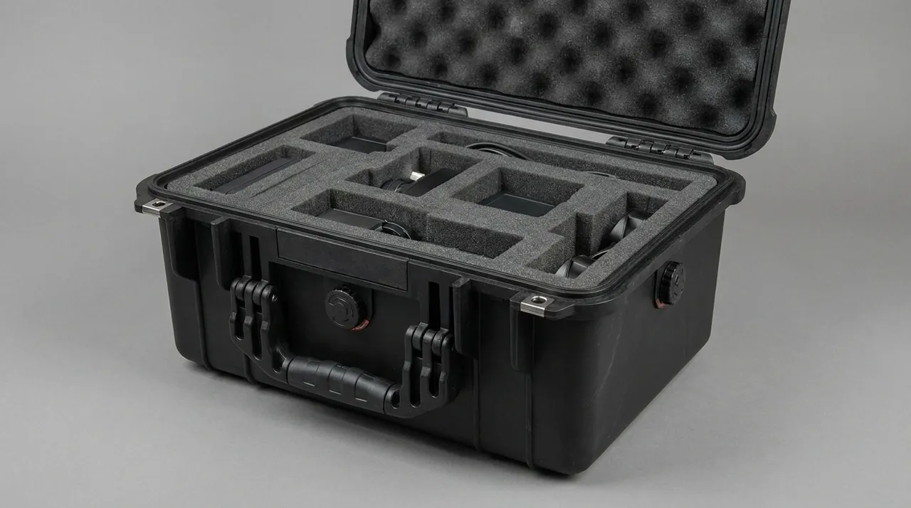
The standard field approach is to mill a row of locating holes in a high-density EVA or PU insert at the valve pitch, with hole diameter 0.2 to 0.5 mm larger than the stem and a depth covering most of the stem length. Once the stem is surrounded by the hole wall, lateral vibration is constrained and bending risk falls sharply. The disc rests on a counterbore or a soft pad so the disc face is not directly loaded. The seat angle face should point upward or toward open space and must never touch a hard object.
On bundling loose valves. Some shops save time by bundling dozens of valves with a rubber band and bagging them. This almost guarantees stem-to-stem scoring and angle-face impact, because under transport vibration the bundle produces continuous fretting wear whose damage accumulates.
On surface treatment layers. The hardened layer on nitrided or chrome-plated valves is hard but relatively brittle, and local concentrated loading can chip it. Contact areas in the insert should therefore avoid hard sharp edges and spread contact stress as widely as possible. For electronic control components such as solenoid valves and sensors that need static protection, the approach in ESD shield case provides the shielding and grounding logic.
3. Tappets and Hydraulic Lifters: Mating Faces, Oil Galleries, Lash Control
The tappet is the valve-train component most sensitive to both accuracy and cleanliness. Mechanical and hydraulic tappets differ in detail, but they share one requirement: mating faces must never be scored and oil galleries must never be blocked.
- Mechanical tappets (flat and roller). The base contacts the cam, and its hardness and roughness are specially controlled. Roller tappets also contain a roller, pin and bearing structure. Priorities are an unscored base, a freely rotating roller and a pin that does not shift.
- Hydraulic lifters (hydraulic lash adjusters). These contain a plunger, a check valve, a high-pressure chamber and a low-pressure chamber, with extremely small clearances. Three things destroy a hydraulic lifter in transit: particle contamination, air ingress and oil loss. Particles jam the check valve, air causes start-up noise, and oil loss extends the re-prime time at first start.
- Tappet guides and bore bushes. Precision fits with sensitive bore accuracy, vulnerable to impact and distortion.
- Valve guides and seat inserts. Guide bores are extremely accurate and seat inserts are lapped to the valve, so both are vulnerable to impact. Seat inserts are thin-walled rings and also prone to oval distortion.
- Rockers and rocker shafts. Rocker ball sockets, rollers and shaft bores are all mating faces, and the rocker shaft is a slender shaft vulnerable to bending.
Hydraulic lifter packaging points, which are the most commonly mishandled.
- Keep the factory orientation and oil seal state. Many hydraulic lifters ship with hydraulic or rust-preventive oil already charged. Packaging should preserve that state rather than stripping, cleaning or inverting the part, which lets oil escape and air enter.
- One part per compartment, never stacked in bulk. The plunger and body must not carry any axial stacking load.
- Control the storage attitude. Follow the supplier's requirement on upright or horizontal storage, and avoid long-term side storage, which redistributes internal oil.
- Control temperature. Heat accelerates seal ageing and oil oxidation, so long-term storage should stay in a normal, dry temperature band.
- Move to the warehouse on arrival and use first in, first out. Hydraulic parts have a shelf-life concept. Long storage degrades performance, so marking should include the production batch and a recommended use-by date.
For how precision parts dissipate shock energy in transit, seal and shock case design organizes cushioning layer configuration and energy dissipation paths, and can be used directly when designing a lifter insert.
4. Camshafts, Rockers and Valve Springs: Shafts and Elastic Parts by Zone
The valve train also contains parts whose protection logic is entirely different and needs separate treatment.
Camshafts and rocker shafts, the long shaft parts. The key failure modes are bending and journal scoring. A camshaft carries several cams and journals. The journals are precision ground, and cam lift profile accuracy sets valve timing directly. Protection points are as follows.
- Full-length multi-point support, with support spacing not too wide, to prevent mid-span deflection.
- Cams and journals must not carry load. Support points should sit on non-working sections between journals or on dedicated support positions.
- Axial restraint in both directions, to stop the shaft sliding inside the case and striking the ends.
- Separate compartment. Never share a compartment with heavy parts.
Valve springs and spring sets, the elastic parts. The key failure modes are permanent deformation and free-length change. A spring stored under compression develops stress relaxation and a shorter free length. Therefore:
- Springs must be stored in the free state and must not be additionally compressed when packed.
- Springs supplied in sets should keep their original bundled or separated state to avoid tangling.
- Elastic parts need rebound space in the insert; never force them into an over-tight cavity.
- Large springs and small inner or outer springs should not share a compartment.
Keepers, retainers, seals and valve stem seals, the small parts. Large in number and small in size, these are the highest-risk items for loss and mix-up. The logic is compartments plus countability.
| Small part | Feature | Protection point | Recommended insert form |
|---|---|---|---|
| --- | --- | --- | --- |
| Valve keepers | Two-piece, small and hard | Prevent scattering and size mix-up | Small pocket tray with fixed quantity per pocket |
| Retainers and seats | Ring shaped, thin walled | Prevent oval distortion and cone scoring | Cylindrical pockets, one part per pocket |
| Valve stem seals | Rubber, elasticity sensitive | Prevent compression set and heat ageing | Separate pockets, stored away from light |
| Circlips and retaining rings | Elastic thin parts | Prevent distortion and loss | Slot-type insert or compartment box |
| Adjusting shims | Thickness graded, many sizes | Prevent size mix-up and face scoring | Compartments by thickness with marking |
A note on mixed loading. Valve-train component sizes often differ by only a fraction of a millimetre and cannot be distinguished by eye. If different sizes share one compartment, the line can easily install the wrong part, and the error typically only surfaces at engine bench test or in early reliability testing. Compartment by size plus compartment marking is the cheapest poka-yoke available, and it costs far less than one mis-installation.
For adjustable dividers in mixed multi-size scenarios, the removable divider system describes how movable dividers let one case serve several sizes.
5. Cleanliness Control: ISO 4406 Particle Awareness and Mating Face Protection
For valve-train parts, cleanliness is not a matter of looking clean. It is a quantifiable technical requirement.
ISO 4406 describes particle contamination using classes that express the number of particles in different size bands per unit volume, and it is the common language of hydraulic and lubrication cleanliness control. Engine mating-face cleanliness evaluation often combines other methods, but the ISO 4406 approach provides a directly usable idea: particles are banded by size, counted, and rated so that "how clean" becomes reproducible.
At the packaging stage, cleanliness control can be implemented on four levels.
- Packaging materials must not be a contamination source. This is the most commonly missed point. Paper inserts, newsprint and recycled board shed fibre and dust; low-grade foam sheds crumbs; an uncleaned wooden crate brings wood chips and dust. Every material that directly contacts a part should be low-shedding, low-outgassing and compatible with the part material.
- Parts must be cleaned and dried before they go in. Residual cutting fluid, grinding chips and cleaner residue are all contamination and corrosion sources. Cleaning must be followed by complete drying, especially of bores, oil galleries and threaded blind holes.
- The packing environment must match the cleanliness class. Critical precision parts such as hydraulic lifters and injector-class mating pairs should be packed in a clean area, or at least a dust-controlled one, rather than near the floor of an open shop.
- The case itself must be cleanable. One advantage of engineering plastic cases is that they can be wiped, blown out or even low-pressure washed, so contamination from a previous batch can be fully removed. Metal cases need attention to dust traps at welds and corners.
Protecting mating faces is an extension of cleanliness control. Valve cone faces, tappet bases, camshaft journals and rocker ball sockets are all surfaces whose fit precision determines function. They should never rub against any material. Workable practices are:
- Use a lint-free separator layer such as non-woven fabric or PE film as the direct contact layer.
- Use profile-fit location to constrain degrees of freedom so vibration cannot produce relative motion.
- For steel parts needing rust protection, use a dry rust-preventive film rather than heavy oil, reducing cleaning at the destination.
A detail that is routinely missed: insert milling debris. After CNC milling an EVA or PU insert, a large amount of fine debris remains inside the cavities. If it is not removed, that debris settles onto part surfaces during vibration and becomes particle contamination. Every custom insert should be blown out and visually confirmed before shipment, and this step should appear in the inspection record.
6. Rust and Condensation: Ocean Freight, Climate Shifts and Re-Rusting
Valve-train corrosion risk comes from both material and situation. Valves are commonly alloy steel or martensitic heat-resistant steel; camshafts and rocker shafts are often alloy cast iron or forged steel; lifter bodies and plungers are precision ground. Any ground surface lacks a protective oxide layer and corrodes faster than an ordinary surface.
The first principle of rust prevention is still humidity control. Specific measures are:
- Surface treatment. Apply a rust preventive compatible with later assembly to ground and mating surfaces. Because assembly is usually not preceded by deep cleaning, prefer thin products that are easy to remove or compatible with engine oil.
- The boundary of VCI. Vapour corrosion inhibitor works well on carbon and alloy steels but carries risk for copper, brass, zinc and cadmium plating. Packaging for parts with copper bushings, zinc plating or copper alloys must have compatibility confirmed first. VCI paper must not directly touch a ground surface and needs room for vapour diffusion.
- Trade-offs in vacuum bagging. Vacuum packaging is excellent against rust but risks puncture on sharp corners, and once the bag is opened the advantage disappears. Use it for small, sharp-corner-free, high-value parts, and add desiccant inside.
- Desiccant sizing. Estimate from the free space inside the case: normally 1 to 2 kg of high-efficiency desiccant per cubic metre, doubled for long ocean voyages, with a humidity indicator card readable on opening.
- Sealing and differential pressure. A fully sealed case develops a differential as temperature changes, which shortens gasket life and makes opening difficult. A pressure equalization valve balances the differential while maintaining the IP rating, as explained in case pressure equalization valve.
- Gasket and rust-preventive compatibility. The case gasket must not swell or harden because of rust-preventive vapours; see seal material and case compatibility.
Typical causes and countermeasures for re-rusting after unpacking.
| Symptom | Common cause | Countermeasure |
|---|---|---|
| --- | --- | --- |
| Broad flash rust at unpacking | Parts not fully dried, long-term high humidity inside | Drying sign-off, adequate desiccant, humidity indicator card |
| Local pitting, often in bores and threads | Cleaner residue trapped in blind holes | Blow out blind holes and threaded roots, use protective plugs |
| Mating faces dull with fingerprint marks | Residual hand sweat | Wear clean gloves, never touch precision faces bare-handed |
| Sticky gasket surface | Incompatible with rust preventive or cleaner | Confirm material compatibility, pack by zone |
| No rust on arrival, rust appears days after opening | Bag punctured or contaminated environment after opening | Move parts to storage or production promptly, avoid open-air delays |
Ocean export programs need one additional consideration. Container interiors cycle through hot days and cool nights, producing repeated condensation, and materials inside the case can see wide temperature and humidity swings. MIL-STD-810H can serve as the methodological basis for environmental testing, tailored into a program-specific temperature and humidity cycle profile. It must be stated clearly that MIL-STD-810H is an environmental test method standard, and adopting it does not mean a product has obtained any military certification.
7. Impact Protection: Compartments, Profile Fit and Contact Isolation
Impact is the most visible valve-train failure mode and the one easiest to design out.
Three design layers.
Layer one, compartments. Different sizes, different weights and different sensitivities must be separated. The primary purpose of a compartment is not tidiness; it is cutting the load transfer path, so that a heavy part's inertial impact in vibration is not transmitted to a light part.
Layer two, profile fit. A compartment only separates. Profile fit holds. Inside each compartment, the insert's matching cavity constrains the part's degrees of freedom. As a rule, cavity tolerance should be part outline plus 0.5 to 2 mm, adjusted for shape complexity. Too loose gives insufficient restraint; too tight makes loading difficult and risks scoring.
Layer three, contact isolation. For accuracy faces such as cone faces, ball sockets, journals and plunger mating faces, add an isolation layer on top of restraint. The isolation layer can be lint-free cloth, PE film or low-outgassing foam, and its job is to break direct material-to-material friction.
Typical practices to avoid.
- Rubber-band bundling. Parts inside a bundle cannot be located independently and will strike and abrade each other.
- Bubble wrap with tape. Bubble cells rupture under load and lose protection, and tape residue contaminates surfaces.
- Bag into carton. No location, no cushioning, no sealing: three failures at once.
- Mixed sizes in one compartment. High mis-installation risk plus difficult counting.
- Disc face against disc face. Large-area contact plus relative motion equals mutual abrasion.
Handling impacts matter just as much. Even a perfect insert fails if operators tip a whole tray onto a bench to save time. Build handling cues into the insert: mark the extraction direction on each row, screen-print the packing layout on the inside of the lid, and design grip positions into tray-style inserts. These small design details drive a large improvement in actual compliance on the shop floor.

8. Shell Selection: IP65/IP67, IEC 60529 and GB/T 4208
The shell is the outer layer of the system and does two jobs for valve-train parts: isolating the external environment of humidity, dust and rain, and providing a reusable locating base.
IP ratings are defined by IEC 60529 and GB/T 4208, which share classification methods and acceptance criteria. The common grades mean the following for valve-train cases.
| Rating | Dust | Water | Practical meaning | Typical use |
|---|---|---|---|---|
| --- | --- | --- | --- | --- |
| IP54 | Dust protected | Splash resistant | Basic dust protection, workable for short delivery trips | In-plant delivery, dry shops |
| IP65 | Dust tight | Water jets | Resists rain and washdown, strong overall value | Road supply, normal warehousing |
| IP66 | Dust tight | Powerful water jets | Withstands high-pressure streams, suits frequent cleaning | Open transfer yards, frequent washing |
| IP67 | Dust tight | Temporary immersion, typically 1 m for 30 min | Tolerates short immersion and standing water | Ocean export, humid and rainy regions, long aftermarket storage |
Two misreadings need correcting. First, IP67 does not mean long-term submersion; the standard defines temporary immersion. Second, an IP rating describes only resistance to solid foreign objects and water, not impact, crush or static protection, and cannot be used as a strength indicator.
Material choice matched to the situation.
- Engineering plastic cases in PP, ABS, PC or blended compounds. They do not rust, resist chemical attack, can be cleaned, weigh less and insulate well. For most valve-train parts they are the better choice.
- Heavy-duty metal or composite structures. For very heavy items such as a complete large camshaft or a grouped cylinder head set, or where extreme puncture resistance is needed. Watch for corrosion of the case itself and how inserts are fixed.
- Small stackable cases. For line-side delivery and small aftermarket batches, emphasizing stacking stability, clear marking and one-handed opening.
Hardware and flame retardancy. Hinges, latches and gaskets are the life-limiting parts of a case, and their selection points and failure modes are covered in toolbox hinge latch and seal structure. In addition, because cases may enter engine or vehicle plant shops and warehouses, some customers impose a material flame-retardancy requirement. UL94 is the common evaluation method for plastic burning behaviour, with typical classes such as V-0, V-1, V-2 and HB, and the required class and test method should be written into the technical agreement.
JUNZHJIA can build row-arranged locating-hole inserts, individual-compartment inserts and multi-point cradles for long shafts, and can fit reinforced hinges, metal latches, replaceable gaskets and pressure equalization valves, supplying structural parameters and inspection documents on request.
9. Insert Materials and Structure: EVA, EPE, PU and Load Paths
The insert is the body of the protection system. The shell decides whether external force is survived. The insert decides whether the part experiences force at all.
The first step in insert design is not choosing a material. It is designing the load path: weight travels from the part's load-bearing features, such as the valve disc, the lifter body or the non-working sections between camshaft journals, into the insert support faces, into the base frame, into the case floor and finally to the handling interface. That path must not pass through any accuracy surface.
Insert material comparison.
| Material | Density range, typical | Resilience | Compression set | Suitable location |
|---|---|---|---|---|
| --- | --- | --- | --- | --- |
| EVA | Medium to high | Good resilience, CNC machinable | Low | Profile locating holes, load-bearing base |
| EPE | Low to medium | Soft, long cushioning stroke | Medium | Surface cushioning, disc padding |
| PU foam | Medium to high | Excellent resilience, good energy absorption | Low | High-value cushioning, repeated handling |
| XPE | Medium | Dimensionally stable, good weathering | Low | Separator layers, backing plates |
| Non-woven, lint-free cloth | Not applicable | Not applicable | Not applicable | Direct contact isolation layer |
A wider comparison of resilience, density and load capacity is in case foam material comparison, and the full flow from material selection to CNC tolerance is in the EVA foam insert custom process.
Six structural design points.
- Put the load-bearing face on the part's stiffest, least accurate region. For a valve, that means the disc and mid-stem, never the cone face.
- Relieve every accuracy face and protrusion. Keeper grooves, oil gallery openings, threads and sensor ports all need clearance.
- Control compression. For soft inserts, keep compression at roughly 10 to 20 percent of material thickness. Too much compression behaves like rigid contact; too little means no grip.
- Provide a uniform compression face in the lid. When closed, the part should have no jump freedom, and compression must be even.
- Make loading and counting easy. In line-side delivery, handling efficiency directly determines whether the packaging plan is actually followed. Lay out rows to suit the line takt.
- Keep it cleanable and reusable. The insert must hold dimensions through repeated handling and periodic cleaning.
On layering. For high-value parts or mixed loads, a three-layer build works well: a high-density bottom layer for load, a medium-density middle layer for profile location, and a low-density top layer for gentle compression. Each layer does one job, which makes the design much easier to verify.
10. Vibration and Shock: ISTA, GB/T 4857 and ASTM D4169
A completed design is not a proven design. Three standard families dominate verification.
- The ISTA series covers performance test procedures for transport packaging. For industrial packaging such as engine components, ISTA 3E for unitized loads and ISTA 2A for the simulated performance of individual packages are the usual references. See the ISTA transport testing procedure for procedure selection.
- The GB/T 4857 series is the Chinese family of basic transport package test methods, covering vibration, impact, drop, stacking and compression, and is the usual basis for domestic supply programs. See GB/T 4857 transport packaging verification.
- ASTM D4169 uses a distribution cycle framework that combines test sequences by transport stage and risk level, suited to multimodal export programs. See the ASTM D4169 distribution cycle case.
Trimmed test set for a valve-train case.
| Test | Purpose | Key observation |
|---|---|---|
| --- | --- | --- |
| Random vibration | Simulates sustained road and rail vibration | Part migration in pockets, fretting marks on mating faces, fastener loosening |
| Drop and impact | Simulates handling impacts | Shell cracking, insert penetration, valve rows knocked out of line |
| Fixed-frequency vibration | Screens for resonance | Sustained vibration near a part's natural frequency, especially for shafts |
| Stacking and compression | Simulates warehouse and container stacking | Shell distortion, insert compression beyond design range |
| Concentrated impact | Simulates forklift or foreign-object strikes | Local puncture and crush resistance |
| Temperature and humidity cycling | Simulates cross-climate and container conditions | Condensation, corrosion, gasket elasticity at low temperature, insert dimensional stability |
Two practical recommendations.
First, run random vibration and drop first. They cost the least and reveal the most. If parts migrate or mating faces show fretting marks, improve insert structure and location rather than thickening walls.
Second, describe test items honestly. When an equivalent rigid mass substitutes for real parts, the report must state the substitution and the difference in inertial behaviour, otherwise the credibility of the report will be challenged by the customer's quality department. For loads such as a row of valves, meaning many light individual items, mass substitution deserves particular caution because their failure mode of mutual impact cannot be reproduced by a rigid dummy.
11. Packaging Aids: VCI, Vacuum Bagging and Desiccant Boundaries
Used correctly, packaging aids add value. Used incorrectly, they become a risk source. Boundaries for common aids on valve-train parts are as follows.
| Aid | Function | Applicable condition | Not applicable or risk |
|---|---|---|---|
| --- | --- | --- | --- |
| VCI paper or film | Vapour phase corrosion inhibition | Carbon and alloy steel parts in a closed space | Risk of discoloration on copper, zinc and cadmium; confirm compatibility |
| Vacuum bagging | Blocks moisture and oxygen | Small, sharp-corner-free, high-value parts | Puncture at sharp corners; protection lost once the bag is opened |
| Desiccant, silica gel or mineral | Absorbs moisture inside the case | Any sealed case | Poor effect if undersized or placed where air cannot circulate |
| Humidity indicator card | Makes humidity visible | Any sealed case | Useless if placed out of sight |
| Lint-free cloth or PE film | Contact face isolation | Any accuracy face | Low-grade cloth sheds fibre and becomes a contamination source |
| Rust-preventive grease | Surface corrosion protection | Non-mating surfaces | Residue on mating faces causes cleanliness exceedance and first-part defects |
| Air pillows | Filling voids | Irregular void filling | Deflates under load, cannot be a primary cushioning structure |
Several working rules.
- Aids cannot replace structure. With a good insert, aids are supplementary. With a poor insert, aids cannot rescue the design.
- Contact layer materials must be low shedding. Anything that crumbles cannot touch a precision part.
- Desiccant and humidity indicator cards belong together. Desiccant without an indicator card is unmeasured moisture protection.
- VCI needs sealing. VCI requires a relatively closed volume to maintain vapour concentration and performs poorly in an open carton.
- Aids have shelf lives. VCI paper, desiccant and rust preventives all expire, and using them past date is the same as not using them.
On storage-phase environment management. Long-term storage of valve-train parts, especially hydraulic parts, should follow a record of location, temperature and humidity, batch and duration. A practical interval is to check the humidity indicator card and packaging integrity every three to six months, and for parts unused for more than a year, re-confirm surface condition and freedom of motion before returning them to the line.
12. Incoming Inspection, Traceability and AQL Sampling
Both the case and the packaging plan need acceptance. The object of acceptance is not just the case but the packed state as a whole.
A three-layer acceptance structure.
Layer one, case appearance and structure. No cracks or abnormal distortion. Hinges and latches operate freely and lock reliably. The gasket shows no gaps or compression set. Stacking structure is stable and marking is legible.
Layer two, function and performance. Sealing performance is sampled against the declared IP rating using the acceptance methods of IEC 60529 and GB/T 4208. Insert dimensions match the drawing and parts show no visible movement in their pockets. Loading is smooth with no risk of jamming or scraping.
Layer three, packed state and documents. Part quantities and sizes match the packing list with no mixing or mis-loading. Locking and fastening are complete. Desiccant and humidity indicator card are in place. Accompanying documents, including the packing drawing, inspection records and cleanliness statement, are complete.
AQL sampling can follow the established acceptance sampling framework: determine sample size from batch quantity and judge by defect class. For valve-train packaging, the following classification is practical.
| Defect class | Typical items | Judgement |
|---|---|---|
| --- | --- | --- |
| Critical | Wrong size loaded, short quantity, accuracy-face damage, sealing failure | Not permitted |
| Major | Loose insert location, hinge or latch failure, signs of corrosion | Judged against limits with batch traceability |
| Minor | Cosmetic scratches, unclear marking, local insert burrs | Permitted within limits |
The full acceptance and AQL method is described in custom case acceptance and AQL.
Marking and traceability should include at least the following.
| Marking | Suggested content | Form |
|---|---|---|
| --- | --- | --- |
| Part number and revision | Part number plus engineering change level | Durable label |
| Name and specification | Name, main dimensions, material | Label |
| Batch and date | Production batch, packing date | Label |
| Quantity | Quantity per case | Screen print or label |
| Protection and stacking | IP rating, permitted stack layers | Screen print graphic |
| QR code | Link to packing drawing and inspection records | Weather-resistant label |
On one file per case. For high-value or safety-critical parts, build an electronic file for each case recording the packing drawing, inspection results and transfer history. When a quality issue appears at the customer, this lets the team pinpoint the exact batch and packaging step, cutting investigation time from days to hours.
13. Custom Insert Workflow and Selection Decision Tables
A standard workflow that can serve as a supplier technical requirement.
- Information review. Provide the part list with part number, name, size, material, unit weight and quantity, a list of critical accuracy faces, 3D models or 2D drawings, and whether mixed loading is required.
- Concept design. Select the case size and insert structure and issue the insert layout, packing orientation and loading direction drawings.
- First-article trial fit. Check that location is reliable, relief is sufficient, loading is smooth and compression is even.
- Adjust and freeze. Fine-tune cavity dimensions and compression from the trial feedback, then freeze the drawing revision.
- Production and factory inspection. Blow out insert debris, sample dimensions and confirm appearance, supplying inspection records with each case.
- Change management. When a part is revised, revise the insert drawing in step and withdraw the old revision.
For the core dimensions of supplier evaluation, including mold capability, insert machining accuracy, inspection equipment and document completeness, see how to choose a case OEM factory. JUNZHJIA provides an integrated service from part list interpretation and insert concept design through volume supply and OEM or ODM branding.
Selection decision table.
| Situation | Recommended shell | Recommended insert | Priority verification |
|---|---|---|---|
| --- | --- | --- | --- |
| In-plant line-side delivery, small batches at high frequency | IP54 to IP65 small stackable case | Row locating holes, tray style | Handling efficiency, stacking, counting accuracy |
| Domestic volume supply by road | IP65 standard case | Row locating holes plus individual compartments | Random vibration, drop |
| Aftermarket long-term storage | IP65 to IP67 sealed case with desiccant | Compartmented, countable | Sealing, rust-prevention life, marking durability |
| Ocean export across climate zones | IP67 with pressure equalization valve | Full profile, desiccant, rust barrier | Temperature and humidity cycling, stacking, salt fog |
| Long shafts such as camshafts and rocker shafts | IP65 long-format case | Full-length multi-point cradle with axial restraint | Fixed-frequency vibration, deflection check |
| Hydraulic lifters and other precision parts | IP67 sealed case | One per compartment, lint-free isolation, factory orientation held | Random vibration, cleanliness, sealing |
| Mixed small parts in many sizes | IP65 standard case | Adjustable dividers, compartment boxes, marked pockets | Mis-load risk, counting convenience |
Common misconceptions.
- Misconception one: the parts are small, so any packing will do. The smaller the part, the tighter the tolerance, and the larger the relative share of any damage.
- Misconception two: foam removes the need for profile location. Foam cushions, but it does not locate.
- Misconception three: IP67 means long-term submersion. The definition is temporary immersion and cannot be extrapolated.
- Misconception four: VCI paper is universal. VCI carries risk for copper and zinc parts and requires compatibility confirmation.
- Misconception five: insert milling debris does not matter. Debris is a particle contamination source and a hidden cause of cleanliness exceedance.
- Misconception six: one transport test result lasts indefinitely. Part revisions, route changes and case ageing all invalidate it.
Frequently Asked Questions
Q: What damage types are most common in valve transport, and why are rows standing upright safer than bundles lying flat? A: Valve transport damage falls into four groups. The first is stem bending, which happens when valves lie flat with cantilever or two-point support and lateral vibration produces permanent deflection. The second is scoring of the stem and cone face, caused by direct part-to-part contact and friction. The third is chipping of the disc edge, common when disc faces are placed together or the disc is directly compressed. The fourth is chipping of the surface treatment layer, since a nitrided or chrome layer is hard but relatively brittle and fails under concentrated local load. Rows standing upright are safer than bundles for three reasons. First, standing upright aligns the stem axis with the dominant vibration direction, minimizing the bending moment arm. Second, individual location removes every degree of freedom, eliminating mutual impact at the source. Third, vertical rows make counting by row and line-side picking easier, reducing secondary damage from searching through loose parts. Bundles fail because parts inside cannot be located independently, so vibration produces continuous fretting whose damage accumulates and often only surfaces after assembly.
Q: Why is packaging for hydraulic lifters stricter than for mechanical tappets, and what are the key control points? A: The difference comes from internal structure. A mechanical tappet is essentially a single body, so the priorities are an unscored base and roller, plus a pin that does not deform. A hydraulic lifter contains a plunger, a check valve, a high-pressure chamber and a low-pressure chamber with extremely small clearances, and the chambers hold oil. That creates three additional risks: particle contamination jams the check valve and lash adjustment fails; air ingress causes noise and delayed re-prime at first start; and oil loss degrades internal lubrication. Five control points follow. First, preserve the factory assembly and oil seal state and never strip, clean or invert the part. Second, use one compartment per part and never stack in bulk, because the plunger and body must not carry any axial stacking load. Third, follow the supplier's storage attitude requirement, avoiding long-term side storage which redistributes oil and loads one side of the seal. Fourth, control storage temperature, since heat accelerates seal ageing and oil oxidation. Fifth, apply first-in, first-out batch and shelf-life management, and re-confirm condition for any hydraulic part stored for a long period before it goes to the line.
Q: How is ISO 4406 actually used at the packaging stage, and how do packaging materials avoid becoming a contamination source? A: ISO 4406 is a particle contamination classification standard describing the number of particles in different size bands per unit volume of fluid, and it does not directly set packaging material limits. The correct use at the packaging stage is to borrow its rating idea and make cleanliness control quantified and reproducible: particles are banded by size and rated by count, so a technical agreement can state how clean is clean instead of relying on visual judgement. Applied to packaging materials, four measures prevent them from becoming contamination sources. First, every material in direct contact with a part must be low-shedding, low-outgassing and compatible with the part material. Paper inserts, newsprint and recycled board shed fibre and dust, low-grade foam crumbles, and uncleaned wooden crates bring wood chips, so none should contact a precision part. Second, parts must be cleaned and completely dried before packing, with emphasis on bores, oil galleries and threaded blind holes, since cleaning residue is itself a contamination and corrosion source. Third, critical precision parts such as hydraulic lifter mating pairs should be packed in a clean or at least dust-controlled area rather than near the shop floor. Fourth, inserts must be blown out after CNC milling with a visual confirmation recorded in the inspection file, because milling debris is a hidden cause of cleanliness exceedance.
Q: How should IP65 and IP67 be chosen, and why does a sealed case need a pressure equalization valve? A: IP65 means dust tight and resistant to water jets; IP67 means dust tight and able to withstand temporary immersion, typically 1 metre for 30 minutes. Match the rating to the situation. For in-plant line-side delivery and dry shop environments, IP54 to IP65 is sufficient. For domestic volume supply by road, IP65 usually offers the best value. For long-term aftermarket storage, ocean export, humid and rainy regions, and transfer yards exposed to standing water, IP67 is recommended. Remember that an IP rating describes only the shell's resistance to solid foreign objects and water, not impact or theft resistance. A pressure equalization valve is necessary because of physics: in a fully sealed case, temperature changes alter the internal gas volume and create a differential across the shell. That differential has three consequences. It repeatedly compresses or deforms the gasket, eventually causing sealing failure. It makes the case hard to open, so crews may pry with tools and damage latches. In extreme cases it can force the gasket open, allowing an immediate exchange with humid outside air. A valve lets gas pass slowly once the differential exceeds a threshold while a hydrophobic membrane maintains the IP rating, which is why it often matters more than simply raising the IP class.
Q: What extra packaging preparation is needed for ocean export of valves and valve-train parts? A: Ocean export adds three tests and four measures relative to domestic supply. On testing: temperature and humidity cycling, to verify whether condensation forms inside during container hot-day and cool-night cycles and whether the gasket retains resilience at low temperature; stacking and compression, because container stacking is normal and the effect of stack height and sustained pressure on insert compression and shell distortion must be evaluated; and salt fog assessment, to judge how effective case hardware and part surface protection are in the salt-laden sea atmosphere, remembering that salt fog is accelerated and results require careful interpretation. On measures: first, use a sealed case with a pressure equalization valve to reduce temperature-driven differentials and gasket fatigue; second, use a dry or thin easy-clean rust preventive so cleaning at the destination is manageable and first-shot oil marks are avoided; third, double the desiccant allowance for long ocean voyages and include a humidity indicator card readable on opening; fourth, inspect and photograph immediately on arrival, re-applying rust protection and replacing desiccant as needed. Export programs should also mark cases bilingually and ship the packing drawing and inspection records with each case.
Q: With so many insert materials available, how should EVA, EPE and PU be selected? A: The logic is to define the functional layer first and then choose the material, not the reverse. A locating layer needs dimensional stability, CNC machinability and resistance to collapse after repeated handling, which suits high-density EVA or PU. A cushioning layer needs a longer stroke and good energy absorption, which suits EPE or medium-density PU. A contact isolation layer needs low shedding and softness, which suits lint-free cloth or PE film. Separator layers and backing plates need dimensional stability and weathering resistance, where XPE performs well. Three indicators determine whether a material is suitable. Resilience decides whether the insert returns to position after repeated loading. Compression set decides whether it fails after long-term compression. Density and load capacity decide whether it can carry the part's inertial load. The common engineering error is using one material throughout: a low-density locating layer shifts because support is insufficient, while a high-density contact layer scores parts because it is too hard. A layered combination is more reliable, letting each layer do one job, with a load-bearing bottom, a locating middle and a compressing, isolating top. Each layer's function can then be verified separately.
Q: Why should the number of valves per case match the production line takt? A: Because whether a packaging plan survives depends on whether the shop floor is willing to follow it. If the quantity per case does not match the line's consumption per cycle, two behaviours appear. Either the remaining parts after opening are left loose on a bench or in an open container and lose protection, or parts from different batches are combined to make up a full case, breaking batch traceability. Both behaviours make a technically sound packaging design fail in the last metre. Matching the quantity to line takt produces three benefits. First, a case goes to the line and is fully consumed, so parts stay in a controlled environment from packing to use and dust and moisture protection is never interrupted. Second, counting and handover become per-case rather than per-part, improving both speed and accuracy. Third, batch traceability becomes finer, so a quality issue can be traced to a specific case number and packing batch. The line takt, consumption per cycle and replenishment frequency should therefore be inputs at the insert design stage, rather than constraints imposed on the shop floor after the packaging is built. This is one of the core differences between a custom insert and a generic packaging solution.
Q: Beyond appearance, what should be checked when accepting a valve-train parts case? A: Use a three-layer structure. Layer one is case appearance and structure: no cracks or abnormal distortion, hinges and latches operating freely and locking reliably, a gasket with no gaps or compression set, a stable stacking structure and legible durable marking. Layer two is function and performance: sealing performance sampled against the declared IP rating using the acceptance methods of IEC 60529 and GB/T 4208, insert dimensions matching the drawing with no visible part movement, smooth loading without jamming, and a functional pressure equalization valve if fitted. Layer three is packed state and documents: quantities and sizes matching the packing list with no mixing or mis-loading, complete locking and fastening, desiccant and humidity indicator card in place, and complete documents including the packing drawing, inspection records and cleanliness statement. One additional check is worthwhile: a visual cleanliness inspection of the insert, focusing on milling debris left in cavities, because this is the most easily missed item that directly affects part contamination. Sampling frequency and acceptance limits should be agreed within an AQL framework, with wrong size loaded, short quantity, accuracy-face damage and sealing failure classed as critical defects that are never permitted.
Conclusion & Related Reading
Packaging engine valves and valve-train components is a specific branch of precision mating-pair protection. Four statements summarize the article. First, the vulnerable points are concentrated in stem straightness, the seat angle face, plunger mating faces and long-shaft deflection, so the insert must constrain freedom through profile location and keep accuracy faces at zero contact and zero load. Second, valves stand upright in individually located rows, hydraulic lifters sit one per compartment holding their factory orientation, and long shafts such as camshafts need full-length multi-point support. Third, rust prevention is a combination of clean, dry, sealed, desiccated and humidity-indicated, with the IP rating matched to the situation and IP67 plus a pressure equalization valve recommended for ocean export. Fourth, cleanliness must be managed quantitatively using the ISO 4406 rating idea, and packaging materials themselves must not become a contamination source.
Written down, these actions become an executable packaging plan: case size and IP rating, insert structure and locating method, packed quantity matched to line takt, rust prevention and desiccant configuration, boundaries for packaging aids, verification test items, marking and traceability content, and the unpacking checklist plus shelf-life management rules. JUNZHJIA can design and supply row locating-hole inserts, individual-compartment inserts and multi-point cradles for long shafts based on the part list, with OEM and ODM support and structural parameter and inspection document output, helping engine component manufacturers turn packaging into a controlled process.
Related Reading