

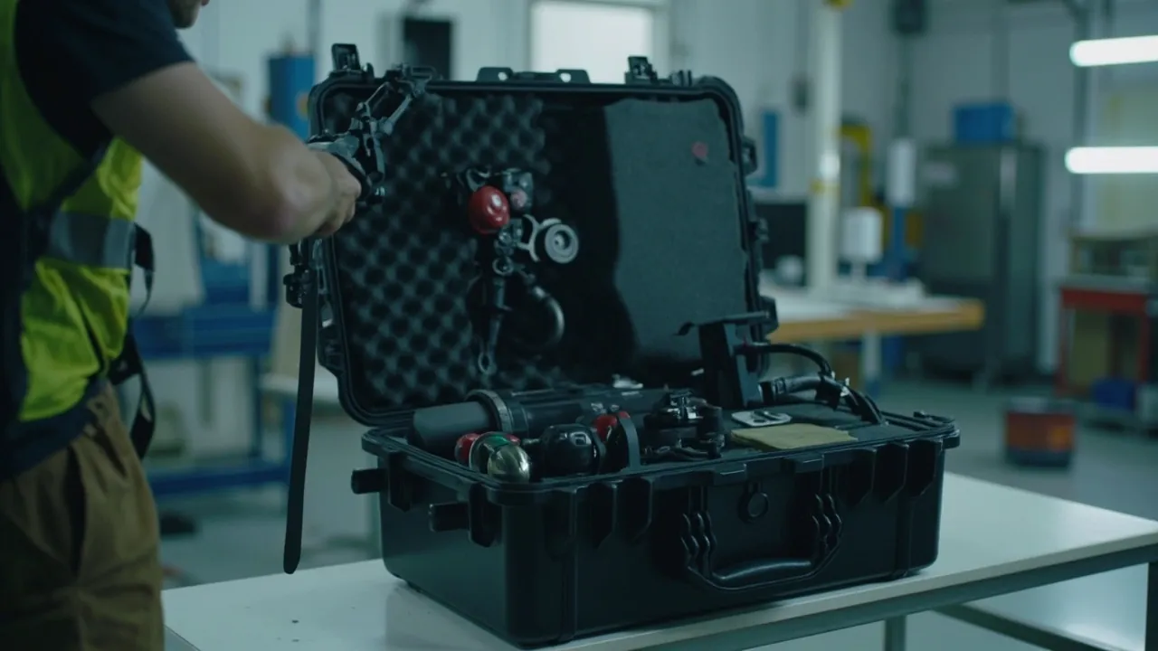
A spring manufacturing parts case has to keep coiling mandrels, forming blades, feed rolls, grinding wheels, shot-blast blades and inspection instruments dimensionally stable, surface-intact and coaxial through in-plant changeover, inter-plant transfer and export shipment. What makes spring production distinctive is that there is almost no buffer between machine accuracy and finished-part accuracy: a 0.02 mm deviation in mandrel diameter can push a coiled spring's inside diameter outside the tolerance band of GB/T 1239.2, and 0.05 mm of grinding wheel face runout shows up as scatter in end-face parallelism. The parts case is not a consumable here; it is a link in the precision chain.
The practical difficulty is that the route is long. A typical sequence in a spring plant runs from the tool crib to the coiler, back to the crib for regrinding, from the main plant to a sister plant or a customer site, and sometimes overseas alongside a fully automatic coiling machine. A slender mandrel 6 mm in diameter and 300 mm long will develop a bend invisible to the eye if both ends are unsupported and transport vibration does its work. A grinding wheel that contacts metal parts inside the case can take a crack in the bond layer from a single impact, and that crack only becomes a risk once the wheel spins at full speed. This article breaks protection down by component type and gives workable practice on case material, IP ratings under IEC 60529 and GB/T 4208, cushioning inserts, rust control, and transport validation with ISTA, GB/T 4857, ASTM D4169 and MIL-STD-810H test methods.
Table of Contents
- 1. The spring production flow and component protection tiers
- 2. Coiler feeding and straightening components: preventing bend in long thin parts
- 3. Coiling mandrels, forming blades and tooling: precision compartment locating
- 4. Grinding wheels and end-face grinding components: brittle parts and dust control
- 5. Heat-treat and tempering furnace components: moisture, scale and hot hardware
- 6. Shot-blast and peening components: wear parts and seal coordination
- 7. Spring inspection instruments: load cells and reference standards
- 8. Case material, structure, UL94 and IK impact requirements
- 9. Sealing and ingress protection: IP65/IP67 under IEC 60529 and GB/T 4208
- 10. Custom inserts and internal locating: EVA/PE foam, channels and layer marking
- 11. Rust and vibration control with transport validation: VCI, ISTA, GB/T 4857, ASTM D4169
- 12. Selection table, load calculation and OEM/ODM acceptance
- Frequently Asked Questions
- Conclusion & Related Reading
1. The spring production flow and component protection tiers
The basic spring production chain runs: wire pay-off, straightening, feeding, coiling, stress-relief tempering, end-face grinding, shot peening, preset (scragging), inspection and surface treatment. Every step has its own tooling and wear parts, and their transport sensitivities differ enormously. Packing them all to one standard creates waste and risk at the same time.
| Tier | Typical components | Dominant failure mode | Key protection measure |
|---|---|---|---|
| --- | --- | --- | --- |
| A (highest) | Coiling mandrels, forming blades, cams, pitch tools | Diameter tolerance drift, edge chipping, face scratching | Individual pockets, axial restraint, soft transition layer, dry rust protection |
| B | Feed rolls, straightening rolls, wire guide tubes, tension rolls | Outside diameter marking, bore fit damage | Bore locating, outside diameter suspended, compartmentalized tray |
| C | Grinding wheels, wheel flanges, clamping discs | Bond cracking, face runout, strength loss from moisture | Face support, vibration pads, moisture-barrier packing |
| D | Shot-blast blades, wear plates, sorting screens, hoppers | Distortion of wear parts, sharp-corner impact, corrosion | Rigid support, hard separation, rust treatment |
| E | Load cells, force gauges, vision measurement lenses | Zero drift, calibration loss, lens scratching | Independent cushioning, vibration isolation, dust sealing |
Tier A components are the hidden assets of a spring plant. A forming cam or a set of pitch tools is expensive, and when it fails it rarely breaks; instead it produces unstable coil counts, pitch deviation or free-length scatter. By the time inspection catches it, several hundred non-conforming parts may already have been produced. Tier A components therefore follow three rules: individual locating, no mutual contact, and no axial movement.
Tier C components carry underrated risk. Resin-bonded grinding wheels are hygroscopic, and prolonged exposure to high humidity degrades strength and balance. If a wheel bears load on its side or strikes a metal component inside the case, a fine crack can form within the bond, and that crack shows nothing at all during slow handling while becoming a hazard once the wheel spins up. This risk has to be designed out structurally rather than caught by visual inspection.
JUNZHJIA's usual approach for the spring equipment sector is tiered, split-case packaging based on the customer's tooling list and precision classes: Tier A parts go into individual cases or individual pockets, Tier B and C parts travel in general-purpose stackable cases with dedicated carriers, and Tier D parts travel in heavy-duty frame cases. Total packaging cost stays under control while the most expensive tooling sits on the most controlled path.
2. Coiler feeding and straightening components: preventing bend in long thin parts
The front end of a coiling machine is a cluster of feeding and straightening components: the pay-off stand, a straightening roll set of five to nine rolls, feed rolls, pressure rolls, wire guide tubes and tension control parts. What they share is length, slenderness, thin walls and precision fits.
Straightening and feed rolls fail in a characteristic way: outside diameter marking and bore fit damage. The outside diameter contacts the wire directly, so once it carries a mark the feed length fluctuates periodically, which shows up as scatter in coil count and free length. The bore is usually a precision fit, so once it is damaged the assembled roll runs out of alignment and the roll itself runs out. The correct arrangement is bore locating with the outside diameter suspended, using a locating arbor through the bore so the outside diameter never touches the case wall or insert.
Wire guide tubes, tension rods and linkages fall into the long-and-bendable class. The dominant transport risk is not impact but accumulated bending from vibration. Three-point or multi-point support is the practical answer, with supports at roughly one-fifth, one-half and four-fifths of the length and soft support between them, so the middle does not sag the way end support alone would allow. Guide tubes longer than 500 mm belong in a dedicated long-item case with continuous channel foam running axially.
One detail is often overlooked on straightening roll assemblies: the bearings or bushings between roll and shaft are precision items, and axial impact in transit can brinell the raceways, which then shows up as noise and temperature rise after assembly. Long-item cases should therefore avoid free axial travel, achieved with elastic stops at both ends that allow limited cushioning but prevent the part from running.
| Component | Typical size | Failure mode | Recommended packing |
|---|---|---|---|
| --- | --- | --- | --- |
| Straightening roll | 40 to 120 mm OD | OD marking, bore damage | Bore locating arbor, compartmentalized tray |
| Feed roll | 60 to 200 mm OD | OD marking, bearing brinelling | Bore locating, elastic axial stops |
| Wire guide tube | 200 to 800 mm long | Bending, tube end deformation | Long-item case, continuous channel foam |
| Tension rod / linkage | 150 to 600 mm long | Bending, thread end damage | Three-point support, end caps |
| Wire guide block | Irregular | Guide face scratching | Individual pocket, working face up |
3. Coiling mandrels, forming blades and tooling: precision compartment locating
The coiling mandrel is the tool that determines a spring's inside diameter. Cold-coiled springs have their inside diameter tolerances controlled under GB/T 1239.2, and mandrel diameter wear translates directly into that dimension. Forming blades, pitch tools and cut-off blades determine coil count, pitch and end-face quality.
Protection for these parts comes down to zero movement and zero contact.
- Zero axial movement. The mandrel must be fixed along its axis. If it can slide inside the case, repeated impact in transit makes the end strike the case wall, producing burrs or a rolled edge. Use elastic end blocks, or narrow the channel locally to grip the mandrel.
- Zero contact. A coiling tooling set typically includes several mandrels and several blades, and they must be separated by the insert. Blades go one per pocket, with cutting edges facing the same direction, never stacked.
- Soft transition. Mandrel working surfaces are often finished below Ra 0.4 and must not rub directly against firm foam; add a non-woven or EPE transition layer.
For mandrels below 3 mm in diameter, bending is the dominant transport risk. The answer is a snug channel matched to the diameter with 0.1 to 0.2 mm single-side clearance, letting the foam itself provide support rather than leaving the mandrel spanning between two end supports.
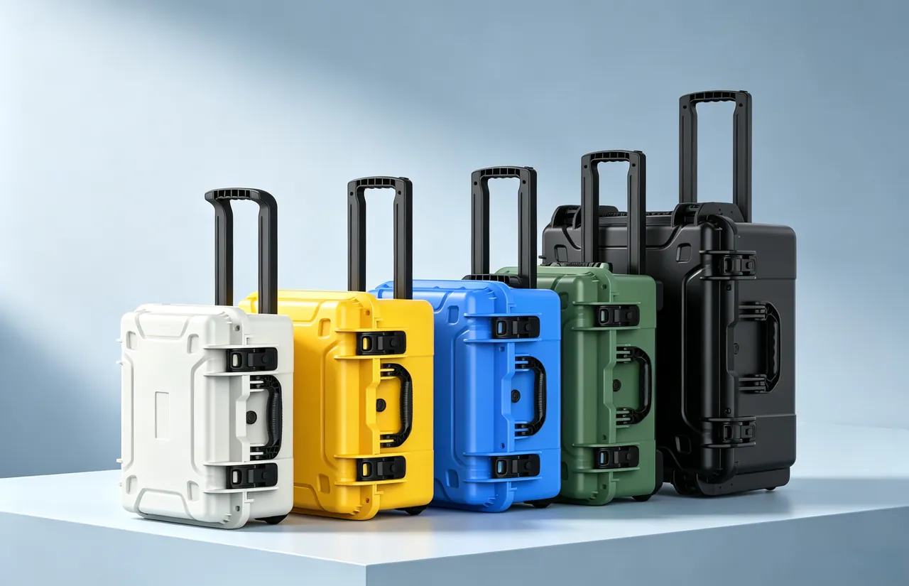
One procedural detail belongs in the work instruction: a mandrel removed from the machine carries oil and metal fines, and packing it directly lets those fines adhere to the working surface as lapping compound. The disciplined sequence is demagnetize, blow clean, apply a very thin rust-preventive film, wrap in rust-inhibiting paper, then pack. For tooling that serves oil-tempered and tempered spring wire meeting GB/T 18983 requirements, this step matters especially.
4. Grinding wheels and end-face grinding components: brittle parts and dust control
End-face grinding determines free length and end-face parallelism, and the associated components include grinding wheels, wheel flanges, clamping discs, feed plates and dressing tools. The core tension here is that a grinding wheel is a brittle body that must withstand centrifugal stress at speed, which means the first packaging objective is not "no breakage" but "no invisible internal damage."
Three principles apply to grinding wheels in transit:
- Face support, never edge loading. Lay the wheel flat, supported across its full face or on a dedicated carrier. Never stand it on edge with point contact, and never cinch it with cord or metal strapping.
- Vibration isolation and moisture control. Resin-bonded wheels are moisture sensitive, and prolonged humidity affects strength and balance; fit desiccant and a humidity indicator card, which is essential for sea freight.
- One wheel per layer. Wheels must be separated from each other and from flanges by dividers or foam pads so they cannot strike one another in transit.
Wheel flanges and clamping discs fail differently, mainly through damage to their mating faces and loss of balance accuracy. A dinged flange causes wheel runout after assembly, which grinds a taper into the end face. Pack them with bore locating and face support, and keep flanges separate from wheels so their weight never rests on a wheel's brittle edge.
Dressing tools such as diamond points and roller dressers are small and valuable, and they are the parts most often tossed into a corner of the case. Give them their own pocket, with the diamond tip facing inward behind a protective cap.
It is worth stating that grinding wheels are safety-relevant consumables whose storage and use are governed by established rules on environment, stacking and pre-use inspection. Case protection serves those rules, it does not replace them. The case solves transport damage; the pre-use visual and ring test still has to happen.
5. Heat-treat and tempering furnace components: moisture, scale and hot hardware
After coiling, springs undergo stress-relief tempering, and some products are quenched and tempered or hot coiled. Transportable components along this line include mesh belts, baskets, lifting gear, furnace guide rails, hot-air circulation fans, thermocouples and protective sheaths.
These components have three characteristics:
- Heavy. A single basket or lifting fixture is commonly 20 to 80 kg, putting substantial load on the case base when stacked.
- Thermal history. After long service between 300 and 900 C, the surface carries a porous oxide layer that accelerates corrosion once moisture is present, and the scale sheds and contaminates mirror-finish tooling sharing the case.
- Irregular geometry. Welded structures with many sharp corners, prone to gouging neighbors.
For load, the case base needs reinforcing ribs or a full tray-style bottom, and stacking strength should be designed at roughly 1.5 times total case weight as a safety factor. For unitized pallet dispatch, verify pallet capacity separately. Following the logic of the GB/T 4857 series, a stacking test should replicate the actual stored layer count and dwell period rather than applying one short load.
For scale contamination, the most effective measure is separation: heat-treat components and precision tooling should never share a case. Where they must, isolate them on separate levels with a solid divider. Components should also cool to near ambient temperature before packing, which avoids creating negative pressure inside the case.
Thermocouples and sheaths need protection from bending and contamination. Striking the measuring junction of a sheathed thermocouple changes its response characteristics, so support the full length and give it its own compartment. Ceramic sheaths should be treated as brittle items.
| Component | Typical weight | Main risk | Packing essentials |
|---|---|---|---|
| --- | --- | --- | --- |
| Mesh belt and guide rail | 15 to 60 kg | Distortion, corrosion | Coiled and fixed, rust-inhibiting paper, rigid case |
| Basket, lifting fixture | 20 to 80 kg | Distortion, scale shedding | Reinforced base, hard separation |
| Fan impeller, fan parts | 10 to 40 kg | Blade distortion, balance loss | Individual fixing, blade protection ring |
| Thermocouple, sheath | Under 5 kg | Bending, junction damage | Full-length support, individual pocket |
6. Shot-blast and peening components: wear parts and seal coordination
Shot peening is the key process for improving spring fatigue life, and the equipment interior sees continuous shot impact, which makes it a classic high-wear environment. Transportable components include blast blades, shot distributor wheels, wear plates, control cages, elevator buckets and dust filter cartridges.
The protection logic here diverges completely from precision parts. The focus is preserving geometry and protecting assembly faces:
- Blades are high-chromium cast iron or wear-resistant alloy, hard and low in toughness, so edges chip easily on impact. Pack them in compartments with the back face loaded and the working arc suspended.
- Distributor wheels and control cages are mating wear parts whose clearance determines how evenly shot is distributed, so their mating faces must not be damaged in transit.
- Dust filter cartridges and seals are consumable soft goods that hate compression and moisture; keep them on a separate layer from metal parts and never under a heavy item.
Shot-blast system seals, whether door gaskets, shaft seals or viewing-window seals, work on the same principle as case gaskets: compression plus elastic recovery. That is why gasket material and the compression window deserve separate confirmation when specifying a protective case. For the underlying figures, see our write-up on matching case hinges, latches and seals, where the compression guidance applies directly to shot-blast equipment seals as well.
7. Spring inspection instruments: load cells and reference standards
Spring quality judgment depends on three families of instruments: dimensional (profile projectors, vision measuring machines, calipers), force (spring testers, force gauges, load cells) and performance (fatigue tester fixtures, preset devices).
Force instruments fear two things above all: overload and vibration. A strain-gauge load cell contains a precision elastic element and bonded strain gauges, and impact can produce zero drift or non-linearity that on-site calibration may not reveal. Packing requirements are:
- Give the cell its own pocket with at least 30 mm of cushioning all around, and never let another part rest on it.
- Keep the axial load direction free of impact in transit, and retain the manufacturer's transport locking device where one exists.
- Include the calibration record and an unpacking checklist, and verify zero and repeatability before putting the instrument back into service.
Vision measuring lenses and projector screens scratch easily, so give them soft independent pockets and dust caps. Reference standards such as master springs, gauge blocks and calibration weights need rust and magnetism control, and weights must also satisfy metrology management requirements so that impact does not change their mass.
For instrument cases in frequent use, the insert should be laid out so that every item has a place and a missing item is obvious, for example one pocket per item backed by a checklist. That protects the instruments and keeps the metrology ledger easier to maintain.
8. Case material, structure, UL94 and IK impact requirements
Spring equipment case bodies are usually chosen from copolymer polypropylene, high-density polyethylene, ABS and modified engineering plastics:
| Material | Impact | Low-temp toughness | Chemical resistance | Typical use |
|---|---|---|---|---|
| --- | --- | --- | --- | --- |
| Copolymer PP | Good | Fair to good | Good | Mainstream industrial tool cases, best overall value |
| HDPE | Very good | Very good | Good | Heavy-duty cases, cold environments, outdoor circulation |
| ABS | Moderate | Moderate | Fair | Instrument housings, appearance-driven cases |
| Modified PP | Good | Good | Good | Anti-static or flame-retardant requirements |
For export to the EU or North America, customers often specify a material flammability rating. UL94 is the common basis for evaluating plastic material flammability, with HB for horizontal burning and V-0, V-1 and V-2 for vertical burning, lower numbers being more demanding. It must be stated that UL94 rates the material, not the finished case; a flammability claim about a finished case requires separate evaluation of the finished structure.
For mechanical impact, the IK rating defined in IEC 62262 (IK00 to IK10) characterizes an enclosure's resistance to impact in energy terms. Precision tool cases in the spring industry are commonly designed around the IK08 (5 J) level, while heavy shot-blast component cases may call for IK10 (20 J). IK performance depends strongly on wall thickness, rib layout and corner radius, and well-placed ribs are usually more economical than extra wall thickness.
Hardware selection affects long-term performance just as much: on instrument cases opened many times per shift, hinge and latch life determines whether the seal can be maintained. On corrosion risk, case material and hardware surface treatment must match the service environment, and coastal or high-humidity plants should specify more corrosion-resistant hardware.
9. Sealing and ingress protection: IP65/IP67 under IEC 60529 and GB/T 4208
IP codes are the most basic and most misread specification on a protective case. IEC 60529, and GB/T 4208 which China adopted equivalently, define the first characteristic digit as protection against solid foreign objects and dust, and the second as protection against water.
| IP code | Dust | Water | Typical spring industry scenario |
|---|---|---|---|
| --- | --- | --- | --- |
| IP54 | Dust protected (limited ingress) | Splash resistant | Short in-plant circulation |
| IP65 | Dust tight | Jet water resistant | Brief outdoor transfer, washdown areas |
| IP66 | Dust tight | Powerful jet resistant | Loading in rain, short port drayage |
| IP67 | Dust tight | Temporary immersion (order of 1 m / 30 min) | Sea freight, container condensation, rainy-season warehousing |
| IP68 | Dust tight | Continuous immersion (per manufacturer conditions) | Specialized water transport |
For spring equipment cases the decision can be reduced to one question: will the case travel by sea? If it will, or if it will enter a high-humidity warehouse in the rainy season, specify IP67. If it only circulates inside and around the plant, IP65 is sufficient and more economical. Where outdoor loading and short port drayage dominate, IP66 is the closer fit.
For sealing details, including dual-lip gaskets, foamed silicone, seal groove cross-sections and the compression window, see the sealing structure of IP67 protective cases. The conclusion here is short: gasket compression should be held between 25 and 35 percent. Below 20 percent leaks are likely, and above 40 percent the gasket takes a permanent set and the case becomes hard to close. On tool and instrument cases opened many times per shift, this matters a great deal.
The tighter the seal, the more pronounced the pressure problem becomes. In air freight or thermal cycling, the pressure difference can make a lid very hard to open or locally suck the gasket out of shape. Precision tool cases that will travel by air or over long road routes should be specified with a pressure equalization valve; see protective case pressure equalization valves for structure and selection.
10. Custom inserts and internal locating: EVA/PE foam, channels and layer marking
The insert is the real protective gear of a parts case. Material properties are as follows:
| Material | Density range (kg/m3) | Resilience | Abrasion resistance | Best suited to |
|---|---|---|---|---|
| --- | --- | --- | --- | --- |
| EVA | 60 to 120 | Good | Good | Precision tooling compartments, frequent access |
| Cross-linked PE foam | 25 to 60 | Fair | Fair | General cushioning, large-area support |
| PU foam | 20 to 45 | Good | Moderate | Instruments, load cells |
| EPE | 18 to 30 | Fair | Poor | Low-cost void fill, transition layer |
| XPE | 30 to 60 | Fair | Good | Water barrier layers, pads |
Spring tool cases most often use an EVA inner locating layer plus a cross-linked PE foam outer energy-absorbing layer. For slender parts such as mandrels and guide tubes, use continuous channels rather than intermittent pockets; for irregular parts such as blades and cams, use machined compartments with the working face up.
Pocket tolerance depends on the process: hot-knife cutting lands around plus or minus 0.5 mm, CNC routing reaches plus or minus 0.2 mm, and die cutting suits high-volume thin sheets. Tier A tooling should be specified as CNC routed with 0.3 to 0.5 mm single-side clearance, while slender mandrels want tighter clearance of 0.1 to 0.2 mm so the foam provides the support. For a fuller comparison, see foam material comparison and the EVA insert customization process.
Two design details belong on the drawing. First, finger access: pockets deeper than 40 mm need a finger relief or a nylon pull tab, otherwise the shop floor will tip the case over to get parts out. Second, layer identification drawings: mark each layer with part numbers and shape outlines to reduce mismatch. For a spring plant running many specifications in small batches with frequent changeovers, layered identification drawings save significant search time.
11. Rust and vibration control with transport validation: VCI, ISTA, GB/T 4857, ASTM D4169
Corrosion of a metal part requires three conditions at once: a metal surface, water, and oxygen with an electrolyte. A protective case controls the water, using sealing and dehumidification to hold internal relative humidity below the critical value for corrosion, commonly taken as about 60 percent RH for carbon steel.
A three-layer system is well established for spring tooling transport:
- Contact layer. Rust-inhibiting paper or film wrapped around the tooling. VCI-bearing products sublimate vapor-phase corrosion inhibitor inside the enclosed space, where it adsorbs onto the metal surface as a molecular film.
- Barrier layer. A VCI film or aluminum-plastic laminate envelope reduces the water vapor transmission rate.
- Moisture absorption layer. Desiccant in the case plus a two-stage humidity indicator card, typically 40 percent RH and 60 percent RH.
One caution is essential: VCI is not a substitute for process rust-preventive oil. VCI depends on an enclosed environment at reasonably stable temperature, and when a case is opened frequently or left open the concentration cannot be maintained and performance drops off. High-frequency tool cases fit a thin oil film plus rust-inhibiting paper; long-term storage and sea freight fit a VCI envelope plus desiccant. Desiccant quantity can be estimated from free internal volume, with a rule of thumb of 200 to 500 g of high-efficiency desiccant per 100 L of free space, taking the upper end for long sea voyages.
On transport validation, three frameworks are commonly used:
- ISTA. ISTA 3A covers single packages up to 70 kg in parcel and LTL service, with drop, random vibration and concentrated impact. ISTA 3E covers unitized loads with compression, vibration and inclined impact. ISTA 2A suits basic single-case verification.
- GB/T 4857 series. China's basic test methods for transport packages, covering vibration, impact, stacking, drop and compression, and the series most often cited by domestic customers.
- ASTM D4169. Organizes test intensity around distribution cycles, well suited to North American customers and complex logistics chains.
In addition, methods 514 (vibration) and 516 (shock) of MIL-STD-810H are frequently cited as the methodological basis for environmental testing. This must be stated plainly: citing MIL-STD-810H means only that its test methods are used. It does not mean the product holds any military certification or qualification.
| Framework | Primary scope | Common sub-tests | Suggested use |
|---|---|---|---|
| --- | --- | --- | --- |
| ISTA 3A | Parcel and LTL single package | Drop, random vibration, concentrated impact | Export express, single-case dispatch |
| ISTA 3E | Unitized load | Compression, vibration, inclined impact | Pallet dispatch, third-party warehousing |
| GB/T 4857 | Domestic transport packaging | Vibration, stacking, drop, compression | Domestic customer acceptance |
| ASTM D4169 | Distribution cycle | Sequences assembled per DC | North America, complex logistics chains |
The practical advice is to copy your actual logistics chain into the test conditions rather than copying a good-looking report. Draw the node map from dispatch to machine installation, mark the maximum drop height, longest vibration duration and highest stack count, and then choose the program. For program details, see ISTA transport testing procedures and GB/T 4857 transport packaging tests.
12. Selection table, load calculation and OEM/ODM acceptance
The most common selection error is choosing a case from the largest component's footprint, which yields an oversized case, too much fill and unstable stacking. The right order is to calculate load and stacking first, then fix external size and structure, and finally lay out the insert compartments.
Load can be estimated as follows, though these are engineering estimates and not test results:
- Total case weight W = sum of component net weights + insert weight + case self weight
- Required stacking strength F = W x stacked layers x safety factor (1.5 to 2.0 recommended)
- For unitized pallet dispatch, verify pallet load separately following the stacking test logic of GB/T 4857
Three sizing rules apply:
- Internal clear size = largest component envelope + insert wall (15 to 25 mm per side) + finger-access allowance.
- External size should align with standard pallet modules, such as a clean subdivision of 1200 x 1000 mm or 1200 x 800 mm, to raise load efficiency and reduce transit damage.
- Keep total case weight in the 25 to 35 kg band. Above 40 kg, add casters, a telescopic handle or forklift pockets. Above 60 kg, design as a palletized unit from the start.
Customers changing over machines across multiple plants should also plan for returning empty cases. A nestable design can cut return volume by 40 to 60 percent, and with the many-specification, small-batch rhythm of a spring plant that saving usually exceeds the price difference on the cases.
For acceptance, sampling beats both full inspection and no inspection. The counting-sampling logic of GB/T 2828.1 offers a workable scheme: a tighter AQL for critical characteristics such as sealing, hardware function and insert pocket location, and a looser AQL for color variation and printing. See custom case acceptance AQL sampling for details.
On delivery capability, JUNZHJIA is manufactured by Kexin New Materials (Guangdong) Co., Ltd. and serves wholesale, distribution, OEM/ODM and global supply. We build foam inserts and compartments to a customer's tooling list, match seals and hardware to the case platform, and can supply material and test documentation for a quality department to file. For spring customers we generally recommend a prototype run using one specification's mandrel and blade set, validated through the real logistics chain before committing to volume. When comparing quotes, include lifecycle cost: a case that is 30 percent cheaper but distorts and leaks within two years usually costs far more in tooling repair and corrosion rework than the price difference, and service-life expectations are covered in protective case service life.
Frequently Asked Questions
Q: How should I select a parts case for a coiling machine, and which parameter should be fixed first?
A: The first parameter to fix is not case size or IP rating but the precision class of the tooling and the length of the longest item. Spring plant tooling carries two risk families: precision items such as mandrels, forming blades and cams, which fail through diameter tolerance drift and edge chipping, and long slender items such as guide tubes and tension rods, which fail through accumulated bending from vibration. Select in this order. List the tooling, individual weights and precision classes, and determine the longest item, since that normally sets the case length. Then define the insert: machined compartments with 0.3 to 0.5 mm single-side clearance for precision parts, continuous channels with 0.1 to 0.2 mm clearance for slender mandrels, and three-point support with end caps for long guide tubes. Only then choose the IP rating: IP65 under IEC 60529 and GB/T 4208 is enough for in-plant and local circulation, while IP67 is advisable for sea freight or high-humidity warehouse storage in the rainy season. If heat-treat baskets share the shipment, separate them into different cases or at least onto separate levels.
Q: How do I prevent damage to coiling mandrels and forming blades, and what are the hard packaging requirements?
A: Three hard requirements summarize it: no axial movement, no mutual contact, soft transition. No axial movement means the mandrel must be fixed along its axis, with elastic end blocks or a locally narrowed channel that grips it. If a mandrel can slide inside the case, repeated impact in transit makes its end strike the case wall, producing burrs or a rolled edge. No mutual contact means that since a coiling tooling set usually contains several mandrels and several blades, the insert must separate them, with blades one per pocket, cutting edges oriented consistently and never stacked. Soft transition means mandrel working surfaces are often finished below Ra 0.4 and must not rub directly against firm foam, so add a non-woven or EPE layer. One procedural point is easily missed: a mandrel removed from the machine carries oil and metal fines, and packing it directly lets those fines adhere to the working surface as lapping compound. The disciplined sequence is demagnetize, blow clean, apply a very thin rust-preventive film, wrap in rust-inhibiting paper, then pack. Whether this step happens determines whether a mandrel survives three regrinds or eight.
Q: What should I watch for when transporting and storing grinding wheels, and why can they not be packed like ordinary metal parts?
A: Because a grinding wheel is a brittle body that must withstand centrifugal stress at speed, so the first packaging objective is not "no breakage" but "no invisible internal damage." Three principles apply. First, face support and never edge loading: lay the wheel flat, supported across its full face or on a dedicated carrier, do not stand it on edge with point contact, and do not cinch it with cord or metal strapping. Second, vibration isolation and moisture control: resin-bonded wheels are moisture sensitive, and prolonged humidity degrades strength and balance, so fit desiccant and a humidity indicator card, which is essential for sea freight. Third, one wheel per layer, with dividers or foam pads separating wheels from each other and from flanges. Wheel flanges and clamping discs fail mainly through damage to mating faces that causes runout, so locate them on the bore with face support and never let a flange's weight rest on a wheel's brittle edge. Finally, note that the case solves transport damage only; the pre-use visual and ring test on a grinding wheel still has to happen, and packaging protection does not replace the applicable use rules.
Q: How do I keep long slender parts such as guide tubes, tension rods and long mandrels from bending in transit?
A: The answer is support point placement and axial restraint rather than thicker foam. First, support points. The dominant risk for a long slender part is accumulated bending from vibration, not a single impact. The practical approach is three or more support points at roughly one-fifth, one-half and four-fifths of the length with soft support between them, so the middle does not sag the way end support alone allows. Second, channel form. Guide tubes longer than 500 mm belong in a dedicated long-item case with continuous channel foam running axially, so the foam supports the full length instead of leaving the part spanning between supports. Third, axial restraint. Elastic stops at both ends of the case should permit limited cushioning while preventing the part from running, because axial impact on a rolling element or a mating face can brinell a raceway and show up as noise and temperature rise after assembly. Fourth, end protection. The ends of a guide tube deform easily and should have caps or local thickening. Note that a bend is often invisible on arrival while directly affecting coil count and free-length stability, so validation for these parts should prioritize vibration and drop testing rather than a visual check alone.
Q: How do I choose between IP65 and IP67 for spring equipment parts cases?
A: Choose from the harshest link in the logistics chain, not from the shop floor environment. IP65 means dust tight plus protection against water jets, covering in-plant circulation, brief outdoor transfer and washdown areas, and it is entirely sufficient for day-to-day internal movement in a spring plant. IP67 means dust tight plus protection against temporary immersion, in the order of one meter for 30 minutes, and its real value lies in container condensation. Day-night temperature swings inside a sea freight container deposit water vapor as liquid on the case surface, and only a temporary-immersion-rated seal blocks it, which matters especially for moisture-sensitive items such as grinding wheels. The decision rule is simple: will the case travel by sea, or enter a high-humidity warehouse during the rainy season? If yes, specify IP67; if no, IP65 is more economical, and IP66 fits where outdoor loading and short port drayage dominate. Remember that an IP rating is a type test result and real protection depends on the gasket retaining compression, so hold compression between 25 and 35 percent and check hinge and latch clamping regularly. If the case will travel by air or through thermal cycling, add a pressure equalization valve so the lid stays easy to open and the gasket is not sucked out of shape.
Q: Should the insert be EVA or cross-linked PE foam, and what do spring tooling applications prefer?
A: Most spring tool cases use an EVA inner locating layer combined with a cross-linked PE foam outer energy-absorbing layer. EVA is commonly 60 to 120 kg/m3 with good resilience and abrasion resistance, well suited to compartments opened frequently, particularly for precision parts such as mandrels and blades that are handled repeatedly. Cross-linked PE foam is 25 to 60 kg/m3 with a longer cushioning stroke at lower cost, suited to large-area support and the energy-absorbing layer. Why not PU first? PU is 20 to 45 kg/m3, soft and resilient, but only moderately abrasion resistant, and it sheds particles under repeated handling, which then become contamination on precision working surfaces. Density and hardness cannot be judged by feel; load decides. A workable rule is 30 to 38 kg/m3 below 5 kg, 38 to 50 kg/m3 from 5 to 20 kg, and 50 to 70 kg/m3 or a composite structure above 20 kg. On pocket tolerance, hot-knife cutting runs about plus or minus 0.5 mm and CNC routing reaches plus or minus 0.2 mm, so specify CNC routing for Tier A tooling. Finally, do not forget finger reliefs or nylon pull tabs for pockets deeper than 40 mm, otherwise the shop floor tips the case over to remove parts and adds impact risk.
Q: What is a reliable rust prevention approach for spring equipment parts shipped by sea?
A: Use a contact layer, a barrier layer and a moisture absorption layer rather than relying on any single material. For the contact layer, wrap the tooling in rust-inhibiting paper or film; VCI-bearing products sublimate vapor-phase corrosion inhibitor inside the enclosed space, where it adsorbs onto the metal surface as a molecular film. For the barrier layer, use a VCI film or aluminum-plastic laminate envelope to reduce the water vapor transmission rate. For the moisture absorption layer, place desiccant in the case with a two-stage humidity indicator card, typically 40 percent RH and 60 percent RH, so warehouse checks need no unsealing. Desiccant quantity can be estimated from free internal volume at roughly 200 to 500 g of high-efficiency desiccant per 100 L, taking the upper end for long sea voyages. One caution is essential: VCI is not a substitute for process rust-preventive oil, because the mechanisms differ and VCI depends on an enclosed space at reasonably stable temperature, so its concentration cannot be maintained if a case is opened frequently or left open. High-frequency in-plant tool cases fit a thin oil film plus rust-inhibiting paper; long-term storage and export sea freight fit a VCI envelope plus desiccant. Also wear powder-free nitrile gloves before packing, because sweat is a strong electrolyte that can start a corrosion pit within hours.
Q: What does the custom spring equipment parts case process look like, and what should acceptance focus on?
A: A sound flow has five stages: requirement clarification, concept and drawings, prototype, validation and volume production. Clarification needs the tooling list, individual weights and center-of-gravity positions, precision classes, the longest item length, the logistics chain of in-plant, domestic, sea and air legs, whether stacking and pallet dispatch apply, and the target IP rating. The concept stage produces the structure and insert drawings; we recommend prototyping with one specification's mandrel and blade set and running it through the real logistics chain once before committing to volume, which is much safer than a single large order. Validation selects appropriate items from ISTA 3A or 3E, GB/T 4857 or ASTM D4169 based on the logistics chain, with samples built to production structure and process. Where the customer specifies an environmental test methodology, methods 514 and 516 of MIL-STD-810H can be referenced, with the explicit note that this means only the test methods are adopted and implies no military certification. In volume production and outgoing inspection, use a tighter AQL for critical characteristics such as sealing performance, hardware function and insert pocket and layer accuracy, and a looser AQL for color variation and printing, following the counting-sampling logic of GB/T 2828.1. JUNZHJIA is manufactured by Kexin New Materials (Guangdong) Co., Ltd., serving wholesale, distribution, OEM/ODM and global supply, building inserts to a customer's tooling list with supporting technical documentation.
Conclusion & Related Reading
The value of a spring manufacturing parts case comes down to two outcomes: whether a tool survives more regrind cycles, and whether it can go straight onto the machine on arrival. Neither is achieved by making the case thicker. It comes from grading components correctly, supporting long slender parts properly, assembling a complete moisture and rust control system, and copying the right transport conditions into the test plan. In an industry where precision is life, packaging is an underrated link in the chain.
If you are building a protection program for coiling mandrels, forming blades, grinding wheels or heat-treat baskets, start with a complete tooling list and a logistics chain map, and ask the supplier for the insert concept before discussing the case body. Most rework and damage problems can be eliminated at the concept stage.
Related Reading