


An antistatic protective case is an enclosure built from conductive or static-dissipative materials that isolates the interior from external static sources and gives electrostatic-sensitive gear a controlled storage and transport environment. Its core value is to keep the whole cycle of storage, handling and transfer inside a controlled resistance band, preventing kilovolt electrostatic discharge from friction, induction and human contact that would otherwise destroy circuit boards, sensors, semiconductors and pyrotechnic items. In electronics manufacturing, metrology, medicine and equipment support, the antistatic case is not an ordinary plastic box; it is a system-level product combining shell static dissipation, liner equipotential, grounding interface and environment management. This article explains static generation, resistance zones, material process, rating standards, EPA linkage and maintenance, and gives actionable guidance for selecting, designing and using an antistatic protective case. For static-shielding thinking, also see the ESD shield case.
1. What an Antistatic Protective Case Is
The antistatic protective case is designed for electrostatic discharge protection. Its shell and liner use static-dissipative or conductive materials so surface and volume resistance stay in a controlled band: charges from friction are drained promptly without the fast discharge damage that very low resistance would cause. The difference from a normal storage box is "controlled resistance" rather than "mere containment". A normal box ignores surface resistance; an antistatic case requires a continuous equipotential path from shell and liner to latch, plus grounding at lid opening.
In engineering the case stores printed boards, integrated circuits, optoelectronic devices, sensor modules, precision probes and some static-sensitive pyrotechnics. Its job is not "signal shielding" but "charge control", so the pass criterion is whether surface resistance, point-to-point resistance and ground resistance meet the set grade, not whether it looks metallic. Buyers should ask the supplier for material class, resistance band and test method to avoid ordinary plastic boxes being passed off as professional antistatic products. The resistance grading logic is explained further in the ESD shield case guide.
In form the case appears as all-conductive plastic or metal-sprayed hard cases, injection cases with a static-dissipative foam liner, or portable forms with an antistatic bag and rigid frame. Whatever the form, the core standard is that the gear stays in a controlled resistance environment through both closed and open states, not the surface colour. Batch units should combine the protective case selection guide with parameter decisions that include resistance, size and cushioning together.
2. How Static Damages Gear
Static damage has three main mechanisms: human-body model, charged-device model and field induction. Walking staff, clothing friction or lid opening build thousands of volts; contact with gear discharges and punches through gate oxide. A device sliding on an insulating surface also charges and discharges near a conductor; a strong field does not discharge directly but accumulates latent damage. For modern nanometre devices, even tens of volts can cause soft failure, so protection must address source, path and receptor at once.
Static harm is often latent. A non-fatal discharge may only weaken device parameters; it passes the factory test yet fails early in the field, making traceability hard. This is why antistatic must be "controlled end to end": from storage and transfer to lid opening, any segment outside the controlled environment can inject damage. Transit vibration, dry air and insulating packing all raise charging risk, so the liner should be static-dissipative foam, not ordinary foam. For high-sensitivity gear, follow the equipotential practice in the ESD antistatic protective cases.
Understanding the mechanism helps correct selection. If the risk is mostly human handling, focus on the case ground interface and pre-open discharge; if it is transit friction, focus on liner dissipation and isolation; if it is field induction, add a metal shield layer. Protection is not the stronger the better; an over-conductive surface without equipotential can route external discharge straight into the gear, so match the resistance band to the device withstand voltage and aim precisely.
3. Resistance Zones and Material Choices
The antistatic system is usually split by surface resistance into conductive, static-dissipative and insulative. Conductive is below about ten to the fourth ohm, dissipative about ten to the sixth to ninth ohm, insulative above ten to the eleventh ohm. Liners mostly take the dissipative band so charge leaks slowly without spark; the shell sits between dissipative and conductive depending on grounding. Material choice balances resistance, strength and weight.
Mainstream shell materials include static-dissipative polypropylene, conductive modified engineering plastic, conductive-painted ABS and aluminium-magnesium alloy. Polypropylene resists chemical and low temperature, suiting field sites; conductive engineering plastic is strong and dimensionally stable, suiting precision instruments; aluminium is continuously conductive and light, suiting demanding scenes. Whatever the base, every joint must keep resistance continuous to avoid local insulation from gaps. Sandwich structures are explained more systematically in the composite material case guide.
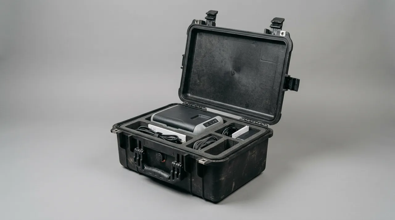
The liner is usually CNC-routed from static-dissipative polyethylene or polyurethane to fit the gear contour, with surface resistance in a device-safe band. Gear should not rest on an insulating wall nor be tied with ordinary nylon. Use routed slots and elastic straps, and ground before opening so gear and shell are equipotential. For mixed loads, separate cells both locate and isolate items and ease counting. Liner design points extend in the custom foam lining case guide.
Liner thickness should follow the drop and vibration profile, not a fixed rule. A good starting point is to size the foam so the gear sits at least ten millimetres from every wall and the cavity holds it with finger pressure but no rattle. Too thin a liner lets the gear bottom out on impact; too thick wastes space and weight. Document the foam grade, density and routed depth in the one-case-one-file so a later re-cut matches the original. Where gear has fragile connectors, add a relieved pocket and a retaining strap so the connector is supported, not cantilevered, during transit.
4. Equipotential, Grounding and Lid Opening
The ground interface of an antistatic protective case is the key link in the protection chain. The compliant method is a dedicated ground point on the case; before opening, a wrist strap or ground wire connects case, person and earth to equipotential, then the gear is taken out, avoiding a charged person touching devices directly. Grounding is not "just one wire"; confirm ground resistance and connection reliability and check the wire regularly.
Lid opening follows a fixed flow. Place on the EPA bench, connect ground, wait for charge balance; use antistatic tweezers, handle gently; before closing confirm the liner is not rolled or dirty. For frequently transferred cases, put a resistance label and ground hint inside the lid and train operators yearly. Ground rules are in the ESD shield case, with dedicated equipotential steps.
Common field errors are replacing grounding with ordinary insulating gloves, opening on dry carpet, or wrapping gear in ordinary bubble film. These seem protective but actually store and keep static. The correct method is static-dissipative packing and grounding throughout, with "ground on open" written into the work instruction. For critical gear, set two-person check: one grounds, one fetches, minimising human error. Cleaning and labelling are in the protective case cleaning guide.
5. Inner Liner and Gear Fixation
The antistatic case still needs cushioning because the gear is mostly precision devices that transit vibration can damage. The liner is CNC-routed static-dissipative foam forming a fitted cavity, surface resistance in a safe band, isolating gear from the metal wall. If the shell is metal, the liner also plays the dual role of insulation and dissipation, preventing hard contact discharge.
Fixation must not break equipotential. Gear should not press a hard point on the metal wall nor hang on ordinary nylon ties. Use embedded routed slots and elastic straps so gear is located in all six directions. For parts with pins or connectors, leave a matching groove to avoid bend or wall-contact discharge. Fixation rules in the ESD antistatic protective cases also apply.
Liner and shell must be "no short, no float". If the liner is conductive and touches the shell, confirm this is intended, not accidental; if the liner is dissipative-insulating, keep a buffer gap between gear and wall. For mixed loads, independent routed cells locate and isolate, avoiding collision damage and speeding inventory. For complex shapes, scan in three dimensions first, then program routing so cavity tolerance stays controlled.
6. Latches, Hinges and Opening Life
The latches of an antistatic case must both secure physically and keep liner-shell equipotential when closed. Butterfly, press and three-point linked latches are common; the three-point lock balances pressure and reduces corner gaps. Hinges should be continuous metal piano hinges whose long overlap forms a conductive path, better for continuity than scattered hinges.
Opening life is evaluated by usage. Static-dissipative foam loses spring-back after repeated compression and is replaced on schedule; metal-shell latches in salt-spray and high-humidity need anti-corrosion to prevent rust breaking conductive contact. For high-reliability electronics and metrology, follow the lessons in the protective case accessories guide and write opening life and ground reliability into the specification.
To extend life, avoid violent opening and foreign objects in the seam. Before closing confirm the liner is not rolled or dirty; after closing check every latch. For frequent transfer, keep an open-cycle log and proactively replace liner and gasket before rated cycles, swapping "failure replacement" for "preventive replacement" to keep resistance stable and lower static risk. Critical-post cases can set a forced-inspection reminder so someone re-tests resistance and replaces the dissipative layer on schedule.
7. Standards and Rating Levels
Antistatic cases usually refer to ANSI/ESD S20.20, IEC 61340 series and GB/T 32304, giving limits for surface, point-to-point and ground resistance. Civil and industrial scenes often use the EPA bench band of ten to the sixth to ninth ohm as the typical dissipative range; high-sensitivity semiconductor scenes are stricter and add ionisers and continuous monitoring.
Testing covers static resistance and dynamic decay. Buyers require a CNAS- or CMA-accredited report with clear test temperature, humidity and electrode layout. Higher conductivity is not always better; an over-conductive surface without equipotential can introduce discharge, so match to device withstand. Resistance and ground rules compare with the ESD shield case guide, whose limits complement resistance tests.
When reading a report, watch the "worst point" not the "best". One spot meeting resistance does not mean the whole surface; real risk may sit at a seam or liner joint. The agreement should state "whole-surface resistance not above a band ceiling" and keep the right to sample by worst point on arrival, preventing suppliers hiding weak spots behind peak data. For batch units, combine first-article qualification with periodic sampling to ensure consistency.
8. Use Linked to the EPA
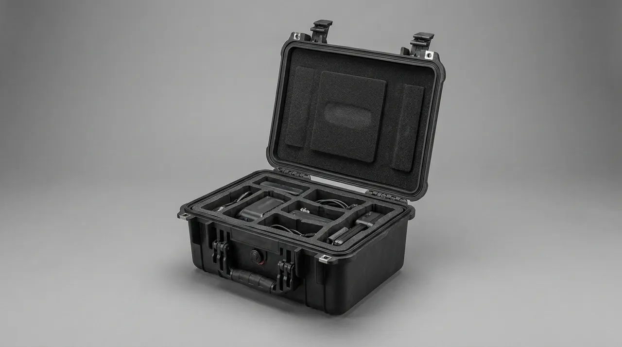
An EPA (electrostatic discharge protected area) is a resistance-controlled workspace; the antistatic case should be opened inside the EPA to minimise risk. In transfer the case acts as a "mobile EPA" moving gear from one controlled environment to another. The link rule: enter EPA, ground first then open; leave EPA, close first then disconnect ground; never expose gear to uncontrolled space.
In electronics shops the case moves boards and half-finished goods between stations, avoiding cumulative damage; in metrology labs it protects standard probes and reference sources from personnel discharge; in medical and equipment fields it secures sensors and controllers during debugging. Transport protection for electronics is in the communication electronics protective case, whose location and buffer methods also apply.
Beyond these, semiconductor assembly, photovoltaic and display lines rely on the antistatic case to keep controlled resistance between stations. Once static-damaged, such gear can drop batch yield or fail early in the field, so the case is paired with full-process monitoring and two-person operation. For cross-border or cross-plant transfer, also evaluate road and vibration risk with the transport vibration testing cases to stop charging from compounding mechanical damage.
A useful pattern is to treat the case as part of a chain of custody rather than a standalone box. At each handover, record the ground-check result, the case serial and the responsible person; on arrival, confirm the ground interface is intact before any field check. If the case carries a location tag, the tag itself should be outside the controlled cavity so it can report position without becoming a leak path, and its battery should be isolated from the inner gear. This discipline matters more than the last ohm of resistance, because a perfectly dissipative case with a broken ground still fails its protection purpose.
9. Difference from Shield Case and Ordinary Box
Users confuse "antistatic case", "EM shield case" and "ordinary box"; their goals differ. The antistatic case controls resistance and drains charge; the shield case isolates RF and blocks eavesdropping; the ordinary box only contains. Structurally the antistatic case relies on dissipative material and grounding, the shield case on a continuous conductive cavity and filters, so materials and interfaces differ.
Clarify the main threat first: static breakdown, RF leak or mere storage. If static is core, prioritise resistance band, dissipative liner and ground interface; if secrecy is core, prioritise conductive continuity and physical seal. The two families can be derived from one shell platform with different liner and interface, so stating the purpose avoids paying for unneeded capability. The detailed comparison is in the ESD shield case guide, with a chapter on equipotential versus shielding trade-offs.
With limited budget, rank by "main risk". For short in-shop transfer with controlled humidity, a dissipative liner plus ground interface is enough; for powered debugging or strong fields, add a shield layer and filtered interface. When modifying stock cases, first assess the original liner resistance before reuse to avoid losing protection from old insulating foam. Any modification should re-test whole-surface resistance and confirm it is still in the qualified band before use.
10. Stacking, Piling and Transport Fixation
Batch transport needs piling stability. Corner ribs and locating bosses let stacked load pass along side walls instead of pressing the lid liner, avoiding permanent deformation of the dissipative layer under long load. Keep pile height within rated layers and use straps or pallet limits. General piling rules are in the protective case stacking guide.
Transport fixation follows "reduce vibration, prevent slip, prevent charging". After gear is located by routed foam, put the case in a tray with antistatic pads; road transport cares about random vibration and shock, rail and air about low-frequency high acceleration. For antistatic cases, straps must not press the lid seam and break equipotential contact. Piling and transport safety are in the seal shock case, whose buffer and locating blocks can be borrowed directly.
For cross-city or cross-border transfer, also plan the case position and buffering inside the vehicle. Place the case at the centre of a damped tray, fixed by locating blocks to avoid collision on hard braking. For long road transport, add an elastic layer between tray and floor to absorb low-frequency vibration. On arrival, re-test key resistance before opening, confirm protection was not harmed, then enter the EPA. For valuable gear, measure resistance before and after transport to form a comparison record, controlling risk before lid opening.
Do not overlook the tray itself. A steel tray with welded corners keeps the case square under stack load, while a thin stamped tray can rack and twist the lid seam. For air transport, the tray should be sized to the unit-load-device footprint and secured with certified restraints; for sea transport, add desiccant and a vapour barrier because the container atmosphere can swing widely. The stacking discipline in the protective case stacking guide applies here too: keep the rated layer count and never rest a second case directly on the lid liner of the one below.
11. Environmental Adaptation and Temperature-Humidity Control
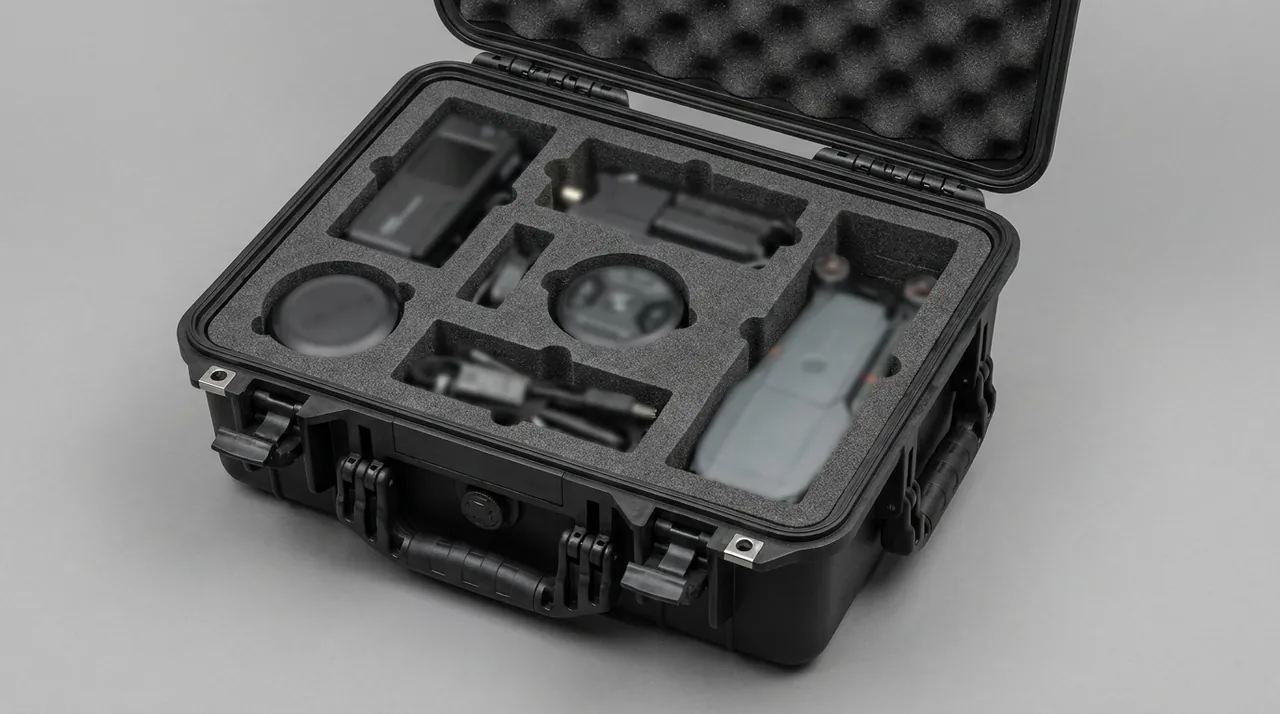
Most antistatic cases are plastic or composite shells; at low temperature the liner hardens and surface resistance rises, at high temperature it may soften. The fix is a dissipative material graded for the use temperature band and controlled opening frequency so internal humidity balances slowly. For high-humidity and tropical use, the shell needs mould treatment and the liner a weather-resistant material to avoid resistance drift after moisture uptake.
For temperature, a plastic shell heats up in direct sun; if the gear has an upper working limit, add a thermal shroud or avoid direct light. High-altitude air transport pressure difference is eased by a pressure-equalisation valve, but the area near the valve is still a resistance weak point, so keep the overlap continuous. Co-design of temperature-humidity and protection grade is in the IP rating guide, treating antistatic, water proofing and humidity control as one system.
In extremely cold or hot regions, also watch liner low-temperature brittleness and high-temperature softening. Static-dissipative silicone and some modified foams keep elasticity at minus forty degrees Celsius, while ordinary foam hardens and loses spring-back when cold. Cold-region selection should specify low-temperature-grade dissipative layer and do a resistance re-check before winter to prevent the liner hardening and weakening location and protection. For tropical long storage, check material weather resistance regularly so UV does not accelerate shell ageing.
Humidity control is not only about desiccant. A humidity card with six or more colour steps gives a quick visual state without opening the case to a gauge, and an electronic logger with a window lets staff read trend without breaking the ground. If the gear inside has a lower humidity limit, set the desiccant quantity from the case volume and the expected transit days, then add a margin for hot, humid legs. Remember that opening the lid in a humid bay can dump more moisture in one minute than a week of slow diffusion, so plan openings for the driest available space and keep them as short as possible.
12. Verification and Arrival Acceptance
Arrival acceptance has three steps. Step one, appearance and resistance: with a surface-resistance meter measure shell and liner points, which should be in the set band. Step two, equipotential: after closing, visually confirm liner-shell contact is even with no break. Step three, send for third-party whole-surface and ground resistance test if needed, keeping data at different points.
Quick field checks use a megohmmeter for point-to-point resistance to confirm the gear contact path is in the dissipative band. In routine maintenance, re-test key resistance quarterly and replace liner, paint or loose ground parts promptly. Suppliers that provide model-specific test files and material certificates sharply lower acceptance risk, a compliance point stressed in the ESD shield case guide. Archive acceptance records as the baseline for later re-tests.
To close the loop, put acceptance results into a "one case one file" of purchase batch, arrival data, past re-tests, liner replacement time and responsible person. Batch units can sample a proportion for re-test to verify consistency. When a batch shows a trend of rising resistance, trace material or process change, stop loss in time and push the supplier to correct. Critical-gear cases can use a two-person acceptance check to avoid single-point error.
A practical acceptance habit is to assign each case a next-inspection date and block its use after that date until serviced, so a case is never opened in the field with an expired liner. For cases that sit unused for years, re-validate resistance before returning them to service rather than assuming the last test still holds, because dissipative elastomers age even in storage. Keep the accredited report with the purchase record and treat it as a contract deliverable, not a marketing extra, so a later dispute can be settled with data rather than memory.
13. Maintenance, Life and Spare Parts
The life weak points of an antistatic case are usually the liner and ground parts. Static-dissipative foam is best replaced every twelve to twenty-four months or by open cycles; metal-shell paint scratches should be re-sprayed with conductive paint promptly to keep resistance continuous. Spare parts list should cover liner, ground wire and lock core.
Long-stored cases should be vented every half month and desiccant dried regularly to avoid internal damp causing resistance drift. Retired cases with residual sensitive information must be de-magnetised or have the conductive layer physically destroyed before scrap. Batch units should keep a "one case one file" of purchase, test, repair and calibration for full-life traceability. Combined protection and maintenance are also in the protective case maintenance guide, whose maintenance cycle can be referenced.
Maintenance should enter budget and cycle management. Liner, desiccant and ground wire are consumables that should be stocked above the minimum to avoid shortage-driven sick use. Critical-post cases can set a "mandatory overhaul on expiry" mechanism where someone replaces the liner on schedule and re-tests, ensuring compliant resistance at all times and turning passive repair into active support. For end-of-life liners, replace the whole piece rather than patch locally, preventing inconsistent resistance between old and new liner causing local insulation.
FAQ
Q: Can an antistatic protective case completely eliminate static? A: No, it cannot absolutely eliminate static. Antistatic means controlling charge in a safe band and draining it slowly, not making charge zero. A qualified case keeps gear from accumulating to the damage threshold during storage, transit and opening through dissipative material and grounding, but dry air, fast friction and ungrounded handling can still charge. The correct method is controlled case resistance, dissipative liner and grounding before opening, plus EPA and work rules as multiple layers rather than a single box. After arrival, also measure the worst-point resistance to confirm whole-surface compliance before use, avoiding misleading by peak data. For extremely sensitive devices, add ion neutralisation and full-process grounding so hardware protection and management close into a loop. Practically, treat the case as one layer in a chain: a perfectly dissipative case with a broken ground still fails its job, so verify the ground at every handover and keep lid openings short in dry bays. Re-test the resistance on a fixed schedule so slow liner ageing is caught before it crosses the protection threshold.
Q: Is a plastic shell with conductive paint reliable for antistatic use? A: It is reliable but depends on coating completeness and thickness. Conductive paint at micrometre scale already gives good dissipation, but pinholes, scratches or edge peeling form local insulation points and raise overall resistance. Engineering practice adds spray and overlap strips at vulnerable corners and avoids frequent friction. For demanding scenes, prefer an all conductive-modified shell; conductive paint suits lightweight, mid-low-grade portable transfer. Either way, provide surface and ground resistance reports and re-test periodically. For batch products, sample-check continuity by batch so individual boxes with uneven spray do not fail and quality variation is controlled at source. Keep in mind that paint is a surface film and can be worn by repeated lid operation or abrasive packing, so inspect the edges at every maintenance cycle and touch up before bare metal shows. Where the case must survive rough field handling, a metal shell with a separate conductive gasket is the more robust choice even if it weighs more, because the protection does not depend on a coating that can be scratched away.
Q: Why use a static-dissipative inner liner? A: Because the printed boards, integrated circuits and sensors being transported are mostly static-sensitive, and friction or contact in transit can generate kilovolt electrostatic discharge that punches through devices or causes latent damage. The dissipative liner keeps surface resistance in a safe range and isolates gear from the metal wall, protecting parts while giving a controlled drain path. The liner material, resistance and replacement cycle should be clearly specified, and the same practice applies in static shield cases. Ground the liner and shell equipotentially and ground before opening to avoid discharge at the instant of lid opening. For multi-cell liners, test surface resistance cell by cell so the whole liner stays in the qualified range with no static blind spot. Note that dissipative is not the same as conductive: a liner that is too conductive can itself couple interference, so select the resistance band that matches the gear class rather than the lowest number. Pair the liner with low-charging foam and avoid wool or nylon that builds static, and log the liner grade in the one-case-one-file so a later re-cut matches the original protection level.
Q: How to judge if supplier resistance data is trustworthy? A: Require a formal report from a CNAS- or CMA-accredited lab stating the test standard, temperature, humidity, electrode layout and case state. Beware of promotions that give only a single maximum with no point distribution. On arrival, do a quick comparison with a megohmmeter; if the gap to the claim is too large, return or claim. In long cooperation, also agree periodic re-test and spare supply terms, and write the "whole-surface worst value" into the technical agreement to stop best-point hiding worst-point and control data distortion at source. For critical projects, ask the supplier to open the test-setup video to confirm the tested state matches the delivered state. A second guard is to specify the exact electrode and dwell used, because resistance numbers shift with measurement geometry; without that detail two reports are hard to compare. Keep the accredited report with the purchase record and re-validate on a cycle, since a liner that passes at delivery can drift after thousands of open-close cycles. Treat the report as a contract deliverable, not a marketing extra.
Q: Will a ventilated antistatic case build static? A: Properly designed, no. The vent uses a metal mesh or grid with conductive overlap, so air flows but charge is drained. The key is that the mesh is resistively continuous with the shell and ordinary insulating punched mesh is not used as a substitute. If the inner gear must work powered, power and signal lines should also enter through suitable interfaces, or the wires become a charging channel. At acceptance, measure point-to-point resistance between mesh and upper shell with a megohmmeter and confirm no abnormal insulation point before judging the ventilation design qualified. For high heat load, enlarge the vent but recalculate resistance continuity so ventilation and antistatic both hold. Remember that the mesh is only as good as its overlap: a visually fine mesh with a discontinuous joint still insulates, so include it in the resistance check along with the lid liner. If the gear does not need to run while sealed, choose the unvented version and cool it only when open, removing the ventilation leak path entirely.
Q: Can an antistatic case be used as a normal water-proof case? A: Structurally they overlap but are not equal. The antistatic seal focuses on resistance continuity and dust, the water-proof seal on liquid blocking, so their gaskets differ. If water proofing, dust proofing and antistatic are all needed, choose a composite product clearly marked with an IP grade whose seal is also conductive, and verify openings block both liquid and charge. Do not assume an antistatic case is necessarily water-proof; check the certification. When buying both, require separate IP and resistance reports from the supplier so one qualification does not substitute for the other. For outdoor long storage, also check the shell weather coating so UV does not accelerate liner ageing. A useful check is to dunk-test the empty case and re-measure resistance afterwards; if the wet liner reads higher resistance than the dry one, the conductive path was partly carried by a water film and the dry-state protection may be overstated. Specifying both ratings in one document avoids that ambiguity.
Q: Does transport compression that deforms the case affect antistatic performance? A: Yes, it does. Local shell dent changes resistance continuity, and lid-seam misalignment makes liner compression uneven and creates gaps, raising local insulation risk. So in piling and lashing, let load pass along the reinforcement ribs and avoid point-pressing the lid seam; the transport tray should add anti-slip and buffer pads. On arrival, if shell deformation is found, first re-test resistance and confirm compliance before use, or repair or replace the liner. For critical gear, measure resistance before and after transport to confirm with data that protection was not harmed, controlling risk before lid opening. For repairable dents, straighten first then re-test; do not use a poorly straightened case. The same logic applies to drops: a corner impact that cracks the weld bead opens an insulation path even if the lid still closes, so include a visual weld inspection in the arrival check and photograph any deformation for the record. Where cases are reused across many trips, set a maximum allowable dent depth in the specification.
Q: What to watch in long-term storage of static-sensitive gear? A: Long storage needs dry environment, regular ventilation and desiccant replacement to avoid moisture-driven resistance drift; monthly check of ground parts and lock integrity with opening records; quarterly re-test of key resistance and liner state. Store away from strong electric fields and high-power RF sources, and stack vertically within rated layers. Keep a one-case-one-file for audit and traceability so the protection chain stays controlled end to end. Retired cases with sensitive information must be de-magnetised or have the conductive layer destroyed before scrap to stop leakage through residual media, extending protection management to the full-life end. Also log storage temperature and humidity and investigate any abnormal swing for impact on resistance or liner state. A practical routine is to assign each case a next-inspection date and block its use after that date until serviced, so a case is never opened in the field with an expired liner. For cases that sit unused for years, re-validate resistance before returning them to service rather than assuming the last test still holds, because dissipative elastomers age even in storage.
Q: Which details are easiest to miss when purchasing? A: The easiest misses are liner life, ground interface and third-party reports. Many quotes give only the shell price, excluding ground wire, spare liner and test files; some suppliers use theory instead of measured values. The technical specification should state resistance grade, test standard, spare list and re-test cycle, and require model-specific test files. For batch purchase, also agree first-article qualification and process sampling to lower systemic risk. Write opening life, low-temperature suitability and arrival sampling rights into the contract to avoid later disputes and protection holes from missing details. For multi-year supply, require a material-change notification obligation so suppliers cannot silently swap liner material and weaken performance. A further blind spot is delivery state versus test state: insist the supplied case is built exactly as the tested sample, with the same liner part number and the same ground interface, and audit a unit from the production batch rather than a hand-built prototype. Closing these gaps in the contract is cheaper than discovering them after a leak.