

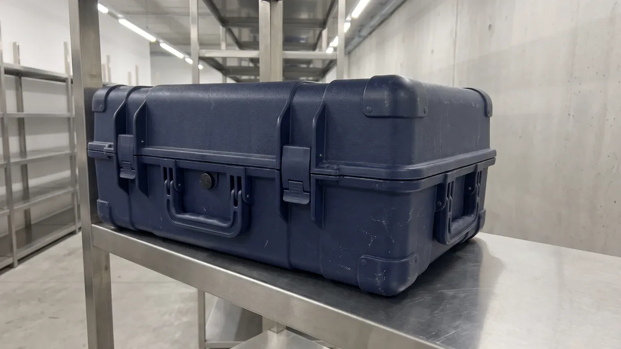
In many protective case failure cases, the problem is not the case itself but the liner failing to fix the equipment, causing it to shake, collide or even crack the lid during transport. Custom foam lining for protective cases embeds each item into an independent slot by cutting cavities to its profile, achieving the synergy of cushioning, positioning and temperature equalization, and is the most direct and cost-effective modification to improve storage and transport safety. This article systematically explains the engineering method of custom lining from four links of material, process, design and acceptance.
1. Function and Value of Custom Lining
The core value of custom lining is "each in its place". General loose sponge only provides overall cushioning and cannot constrain equipment position; under transport vibration, equipment rubs against each other or hits the case wall, with high damage risk. Lining cut to cavity profiles plans exclusive space for each item, absorbing shock and limiting displacement, and reserving cold-air bypass channels to improve temperature uniformity. For multiple set equipment, the lining also undertakes inventory and quick access functions. Compared with replacing the whole case, custom lining costs less and has a shorter cycle, and is an efficient path to upgrade a standard case into a protection scheme. More basics can refer to the Case Foam Lining Guide.
2. Comparison of Common Liner Materials
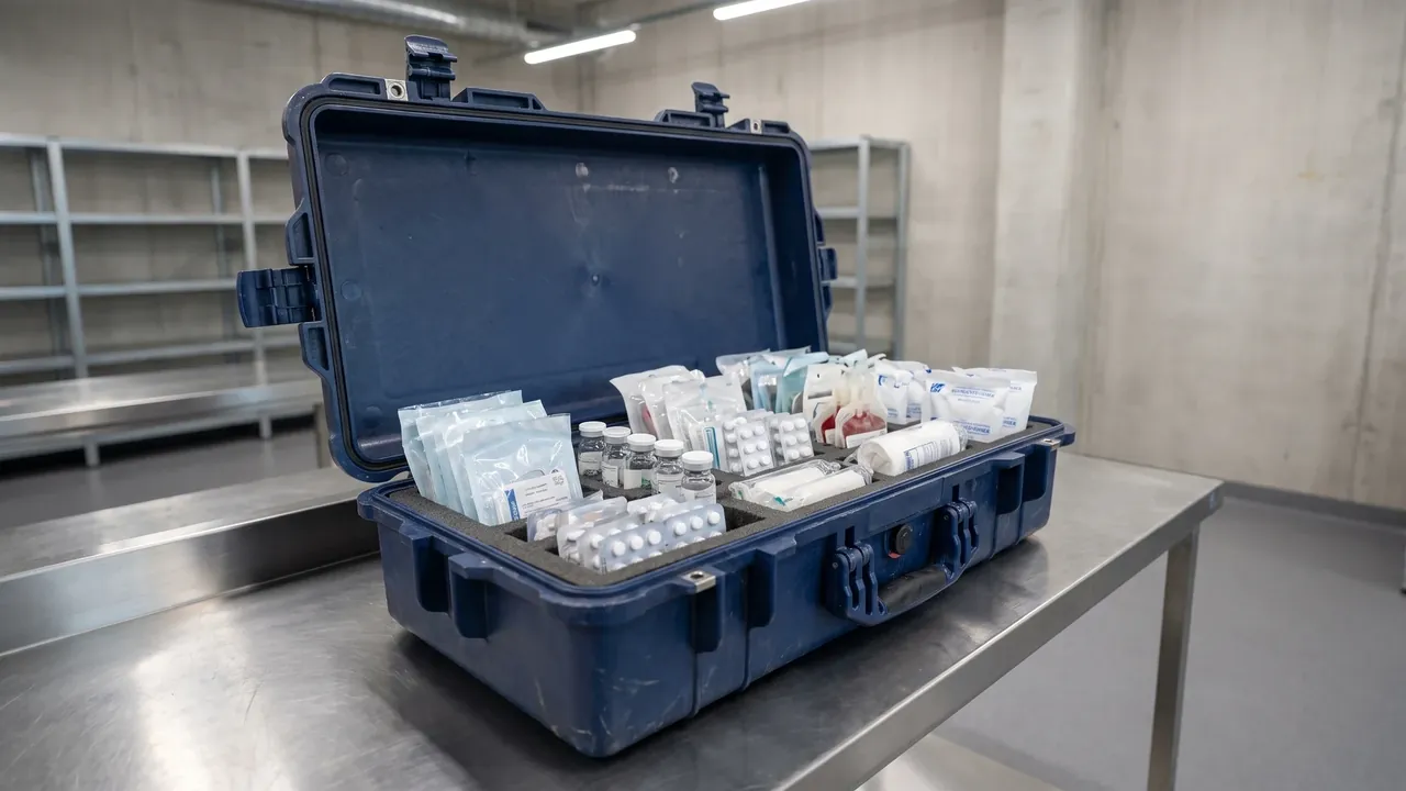
Mainstream liner materials include cross-linked polyethylene, polyurethane, ethylene vinyl acetate copolymer and static-dissipative foam. Cross-linked polyethylene has good resilience, compression resistance and repeated compression tolerance, making it the first choice for general equipment; polyurethane is soft and fits irregular parts but slightly weaker in resilience; ethylene vinyl acetate is easy to thermoform with delicate surface, suitable for appearance parts; static-dissipative foam is used for electronic devices to prevent charge accumulation. Material selection also depends on water absorption and temperature resistance; low water absorption is better for humid environments. For systematic comparison see Case Foam Material Comparison and Case Internal Foam Types. Selection should combine equipment fragility and environment rather than only looking at unit price.
3. Cavity-Cut Process
Cavity cutting means numerically cutting matching grooves on a whole foam block according to the three-dimensional profile of the equipment, so the equipment tightly embeds. The key to the process is dimension collection and cavity layout: first scan or measure the equipment outline, then use software to arrange cavities, ensuring reasonable spacing, no mutual interference, and avoiding case sealing and reinforcement ribs. Cutting methods include numerical control milling, water jet and laser, with different precision and edge quality. Groove depth generally takes two-thirds to all of the equipment height to ensure the center of gravity is covered. Cutting clearance should be negative tolerance tight fit, easy to take and place yet not loose. This process upgrades protection from "soft pad" to "positioning system", significantly improving reliability.
4. EVA and Cross-Linked Polyethylene Forming
Ethylene vinyl acetate liners often use thermoforming, heating the sheet and pressing it into a mold to form cavities, with high efficiency and good consistency, suitable for medium and large batches. Cross-linked polyethylene is mostly milled for cavity cutting, with high flexibility, suitable for small batches and variable cavities. Each has its application: appearance parts and large batches prioritize thermoformed ethylene vinyl acetate; irregular and small batches prioritize milled cross-linked polyethylene. Process details can refer to EVA Foam Insert Custom Process. Regardless of which, first-piece confirmation should be done to check the actual fit between groove and equipment, avoiding deviation between theoretical size and physical object.
5. Pick-and-Pluck and Pre-Cut
Pick-and-Pluck is on-demand tear foam, composed of pre-cut small grids that users can tear off to shape, suitable for temporary or low-frequency scenarios, but with poor precision and aesthetics. Pre-cut liner is cut by the manufacturer according to the drawing in advance, ready to use, balancing flexibility and precision. Both belong to semi-custom, between general sponge and full custom. For initial projects with uncertain equipment layout, Pick-and-Pluck can be used first to verify, then converted to manufacturer pre-cut or numerical cavity cutting. Related methods see Pick and Pluck Foam Guide and Case Pre-Cut Foam.
6. Cushioning Thickness and Clearance Design
Cushioning thickness determines energy absorption capacity and needs to be calculated by combining equipment weight, fragility and expected drop height. Too thin transmits shock directly; too thick wastes space and may push the lid. Clearance design is also critical: the slot should be slightly smaller than the equipment shape for tight fit, but reserve finger space for taking and placing; adjacent slot wall thickness must be sufficient to avoid penetration. For heavy parts, hard support or double-layer foam should be added at the bottom. During design, refer to the empirical parameters in Case Custom Foam Factors. Reasonable thickness and clearance are the basis of both cushioning and positioning and should be verified by measured drop at the prototyping stage.
7. Antistatic and Special Materials
Electronic, semiconductor and pyrotechnic equipment are static sensitive, and the liner needs static-dissipative foam with controlled surface resistance, combined with conductive coating or grounding parts to avoid charge accumulation discharge. Medical and food scenarios focus on non-toxic and low-bleed materials. For high flame-retardant requirements, flame-retardant modified foam can be selected and its rating checked. Special materials are often more expensive and should be selected by equipment risk level rather than applied throughout. For the trade-off between foam and divider, refer to Case Divider versus Foam. Material compliance documents should be obtained together at acceptance.
8. Coordination with Case Sealing
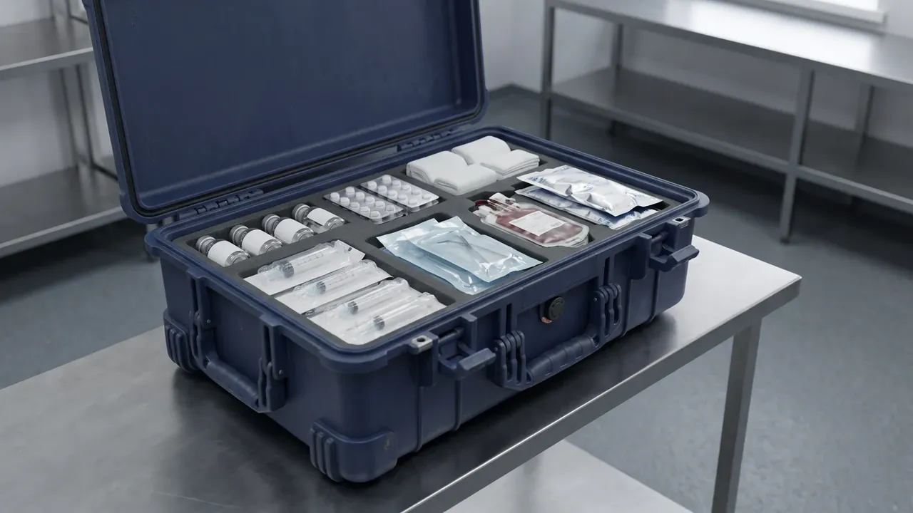
Liner design must coordinate with case sealing, otherwise even the best cushioning is in vain due to lid failure. The total liner height should be lower than the case lid closure margin to avoid deformation or gap under closure. Cavity layout must avoid the door seal line and latch compression area to prevent local lifting that destroys the seal line. For wading cases required by Protective Case IP67 vs IP68, the liner should also be low water absorption and non-ponding to avoid becoming a moisture source. At the customization stage, review liner size and case closure gap together, and if necessary do sample-case immersion and closure verification to ensure the seal is continuous and complete.
9. Liner Design for Temperature-Control Scenarios
In constant-temperature scenarios such as Active Temperature-Control Protective Case, the liner must both cushion and ensure uniform cold-air bypass. Wrong fully-filled liner blocks the air duct, causing local overcooling or excessive temperature difference. The design principle is "point support, leave channels": use island cavities to support equipment, leaving air gaps between equipment and case walls. Low-conductivity, low-absorption materials are more conducive to stability. For temperature-sensitive samples, a temperature-equalizing block or phase-change material can be added at the bottom of the slot to buffer instantaneous disturbance. Liner and temperature control should be verified as a coupled system rather than designed in isolation, and temperature-field testing is recommended into acceptance.
10. Customization Process and Prototyping
The standard customization process includes requirement communication, equipment dimension collection, cavity layout design, first-piece prototyping, fit confirmation, batch production and acceptance. The more accurate the dimension collection, the better the fit; it is recommended to provide physical equipment or three-dimensional model rather than only sketches. First-piece prototyping is the key node; actually place the equipment to check access force and fit, and fine-tune if necessary. Before batch, confirm material, color and labeling requirements. For custom projects, the contract should stipulate mold and intellectual property clauses in Custom vs Standard Case Decision. A standardized process is the premise of stable quality.
11. Reuse and Modification
When equipment is updated or layout changes, the liner does not need to scrap the whole case. The liner can be replaced or modified on the original case through Foam Relining and Recutting, extending case life. For Pick-and-Pluck types, users can adjust by themselves; for numerical cavity-cut types, it is recommended to return to the factory for re-cutting according to the new drawing. During modification, re-evaluate thickness and clearance and check whether sealing and closure are affected. Reuse saves cost and is environmentally friendly, suitable for units with frequent equipment iteration. Establish a liner version ledger recording the equipment list and date of each modification for traceability and spare parts management.
12. Acceptance and Quality
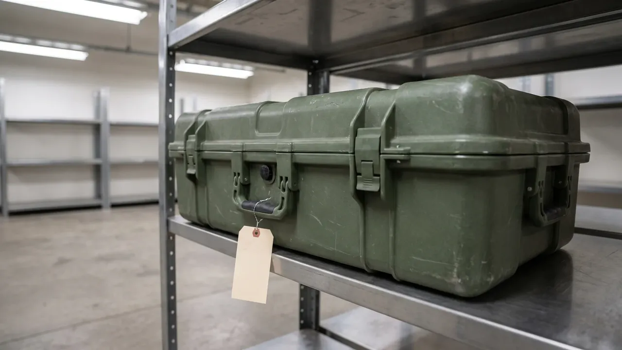
Liner acceptance should focus on four items: fit between slot and equipment, access force, edge quality and material compliance. Too loose fit causes displacement, too tight is hard to access; edge burrs may scratch equipment or personnel; material needs environmental and flame-retardant documents. It is recommended to sample by proportion and combine with load drop testing to verify overall protection. For critical equipment, simulate transport vibration and drop with liner and equipment. Acceptance criteria should be clarified in the contract to avoid subjective disputes. Related basics can refer to Custom Foam Inserts and Custom Foam Inserts Guide.
13. Application Scenarios and Selection Advice
Custom lining is widely used in instruments, medical, electronics, military and outdoor equipment. Set instruments emphasize inventory and positioning; electronic devices emphasize antistatic; military emphasizes stability and confidentiality; outdoor emphasizes light weight and weather resistance. When selecting, first determine material and process, then cavity layout, and finally check sealing and temperature-control coupling. Combine with the overall framework of Protective Case Selection Guide and treat lining as a mandatory step after case selection. For ammunition and equipment storage, also refer to Ammo Box Foam Insert Customization. The final scheme should return to equipment risk level and match corresponding protection intensity.
14. Liner Design Calculation and Cost Optimization
Liner design can also use simple calculation to avoid guessing. The first step estimates cushioning needs: based on equipment fragility value and expected drop height, reverse the required foam thickness, with heavy or fragile parts taking the upper limit. The second step plans cavities: arrange equipment projections within the case net size, leaving equipment spacing, case wall margin and sealing avoidance zone; common nesting software can quickly verify interference. The third step accounts for material usage and labor: numerical cavity cutting is charged by board area, thermoforming by mold and piece count, with small batches prioritizing milling and large batches prioritizing thermoforming. The fourth step does cost comparison: spread liner cost to single case and compare with overall protection benefit.
Several directions of cost optimization deserve attention. One is standardizing equipment size to reduce the number of irregular cavities, thereby lowering cutting complexity. The second is reusing existing cavity libraries, establishing standard slot templates for general equipment, and directly calling them for new projects rather than redesigning. The third is semi-custom transition: use tear foam to verify layout in the early stage, then convert to manufacturer pre-cut or numerical cavity cutting after confirmation, avoiding premature mold investment. The fourth is bidding the liner and case as a whole, with the manufacturer optimizing collaboratively, which is often cheaper and better matched than separate procurement. Combined with the idea of Custom vs Standard Case Decision, the liner strategy should also be dynamically adjusted with quantity and change frequency.
In implementation, it is recommended to list liner design inputs: the equipment list includes weight, shape, fragility value and static requirement; the case parameters include net size, closure margin and seal line position; the acceptance criteria include fit, access force and load drop. Give these inputs to the manufacturer for prototyping, and batch after first-piece confirmation. For units with frequent equipment iteration, establish a liner version ledger and retain rework margin, which can significantly reduce long-term holding cost. Only by treating the liner as a quantifiable and reusable engineering object can a stable balance be achieved between protection intensity and cost, truly realizing the value of Custom Foam Lining.
15. Cross-Scenario Liner Schemes and Trends
Liner schemes continue to iterate with the evolution of equipment forms, and several cross-scenario practices are summarized below. Set instruments mostly adopt layered liners: upper layer for easy-access small parts, lower layer for heavy parts, balancing inventory and center of gravity. Precision optics and sensors emphasize zero indentation, often with velvet surface or soft-hard composite foam, and thin lining on slot walls to prevent scratches. Medical consumables focus on classification and labeling, with liner zones corresponding to different items and color codes established to shorten emergency access time. Electronic batch parts tend to grid-array cavities, achieving high density without mutual contact. The common point of these practices is to treat the liner as equipment management tool rather than mere cushion.
In technology trends, numerical cutting accuracy continues to improve, reducing the cost of irregular cavities; parametric design allows cavity layout to be generated with one click and interference simulated; recyclable and low-volatile materials are driven by environmental regulations; antistatic and electromagnetic-shielding composite foam is popularized in high-end electronic scenarios. Future liners will emphasize modularity and reversible modification, where the same case adapts to multiple tasks by replacing the liner, improving asset utilization. For purchasers, attention should be paid to the manufacturer's digital capability, prioritizing suppliers who can provide three-dimensional design and sample-case data collaboration, and incorporating the liner into product life-cycle management. Grasping these trends can control long-term cost while upgrading protection, allowing Custom Foam Lining to continuously create value.
FAQ
Q: What is custom lining better than general sponge? A: General sponge only provides overall soft cushioning and cannot constrain equipment position; under transport vibration, equipment rubs against each other or hits the case wall with high damage risk. Custom lining cuts grooves according to the three-dimensional profile of the equipment, with each item embedded in an independent slot, absorbing shock and limiting displacement, and reserving cold-air bypass channels to improve temperature uniformity. For multiple set equipment, the lining also undertakes inventory and quick access. Compared with replacing the whole case, custom lining costs less and has a shorter cycle, and is an efficient path to upgrade a standard case into a protection scheme. Its essence upgrades protection from soft pad to positioning system, significantly improving reliability and consistency. In field operations the value goes beyond protection: a visible cavity layout makes missing items obvious at a glance, and pre-shift inventory shrinks from tens of minutes to a few minutes. Custom grooves also stabilize repeated packing, so every team member loads the case the same way, eliminating the variability that comes from personal habits. Over a service life of several years, the lining is typically re-used across hundreds of trips, and the one-time design cost amortizes to a negligible amount per trip. When equipment is upgraded, the grooves can be recut on the same case, so the initial investment keeps paying dividends rather than being written off with each procurement cycle. The habit also simplifies insurance claims with documented packing standards.
Q: How should liner material be selected? A: Mainstream materials include cross-linked polyethylene, polyurethane, ethylene vinyl acetate copolymer and static-dissipative foam. Cross-linked polyethylene has good resilience and compression resistance, the first choice for general equipment; polyurethane is soft and fits irregular parts but slightly weaker in resilience; ethylene vinyl acetate is easy to thermoform with delicate surface, suitable for appearance parts; static-dissipative foam is used for electronic devices to prevent charge accumulation. Also consider water absorption and temperature resistance; low absorption is better for humid environments. Electronic and semiconductor scenarios should choose static-dissipative type with grounding; medical and food focus on non-toxic low bleed; high flame-retardant requirement chooses flame-retardant modified foam. Selection should combine equipment fragility and environment rather than only unit price. A practical method is to build a material file for each equipment category, recording measured resilience, compression set, and water absorption, then match new projects to the database by fragility and environment instead of repeating trials. For mixed loads, hybrid linings are common: only the sensitive slots use static-dissipative or flame-retardant material while the remaining areas use general foam, balancing protection and budget. Also check the supplier's batch consistency, because foam properties drift between lots, and request test reports with each order. When in doubt, prototype with the intended material and run a loaded drop test before committing to volume, since paper parameters rarely capture the full picture. Keep the file updated whenever a supplier or formulation changes, so decisions stay anchored to current data. Review the archive whenever equipment changes.
Q: What is the key to cavity-cut process? A: The key is dimension collection and cavity layout. First scan or measure the equipment outline, then use software to arrange cavities, ensuring reasonable spacing, no mutual interference, and avoiding case sealing and reinforcement ribs. Cutting methods include numerical control milling, water jet or laser, with different precision and edge quality. Groove depth generally takes two-thirds to all of equipment height to cover the center of gravity; cutting clearance should be negative tolerance tight fit, easy to take yet not loose. The first piece must actually place equipment to confirm fit, avoiding deviation between theoretical size and physical object. Standardized dimension and layout are the basis of cushioning, positioning and temperature equalization and should be verified by measurement at prototyping. Edge treatment also matters more than buyers expect: chamfered, deburred edges prevent scratches on both equipment and hands, and they are the most visible difference between a premium lining and a cheap cutting job. When scanning, invest in high-accuracy capture for valuable instruments and smooth the data in software to avoid stepped grooves, then keep tolerance annotations so the design can be reproduced later. Document each cavity with photos of the loaded first article; these records settle future disputes about fit and serve as the reference when ordering replacements. For heavy items, verify that the groove walls carry the load without bulging, since foam creep under sustained pressure can slowly loosen an initially tight fit. A small setup sheet per model keeps future edits fast and error-free.
Q: Will the liner affect case sealing? A: Yes, if designed improperly. If the total liner height exceeds the case lid closure margin, it will be deformed or gap under closure, weakening or even destroying the seal. If the cavity layout pushes against the door seal line or latch compression area, it will cause local lifting and interrupt the seal line. For wading cases, the liner should also be low water absorption and non-ponding to avoid becoming a moisture source inducing condensation. At the customization stage, review liner size and case closure gap together, and if necessary do sample-case immersion and closure verification to ensure the seal is continuous and complete. Accept liner and case as a whole rather than separately to exert cooperative protection. A quick review tool is pressure-sensitive film: place it on the seal line, close the lid, and the color pattern reveals exactly where the liner lifts the cover. For high water-resistance ratings, repeat the closure test after dozens of open-close cycles, because foam creep gradually changes the gap. Keep the liner top surface at least a few millimeters below the lid landing plane, and chamfer any area near the gasket. During acceptance, run a sample-case immersion together with the liner installed, since a case that passed empty can still leak when foam paths wick or bridge the seal. These small checks cost minutes but prevent the most common field failure. Recheck after any liner modification, even minor ones. Liners should always be stored flat to avoid permanent set.
Q: What special requirements does temperature-control case liner have? A: In constant-temperature scenarios the liner must both cushion and ensure uniform cold-air bypass. Fully-filled liner blocks the air duct, causing local overcooling or excessive temperature difference. The design principle is point support and leave channels: use island cavities to support equipment, leaving air gaps between equipment and case walls. Low-conductivity, low-absorption materials are more conducive to temperature stability. For temperature-sensitive samples, add a temperature-equalizing block or phase-change material at the slot bottom to buffer instantaneous disturbance. Liner and temperature control should be verified as a coupled system, with temperature-field testing into acceptance rather than designed in isolation. Only by balancing airflow and cushioning can both protect equipment and stabilize temperature. Validate airflow with multi-point loggers: place sensors at the cold-air inlet, the farthest slot, and a box corner, then compare start-up and steady-state curves. When the spread exceeds your limit, adjust channel width or cavity placement before raising cooling power, which saves energy and improves stability. Avoid fully-filled layouts even when equipment density is high; trade a little packing efficiency for continuous airflow around every item. Phase-change buffers under sensitive slots smooth transient disturbances during door openings or power transfers. Treat the lining and the cooling unit as one coupled system in every review, and re-verify after any equipment change, because a new item can redirect airflow in ways drawings never predict. This discipline keeps thermal performance stable over years of service. Small thermal habits protect expensive samples.
Q: How to choose between Pick-and-Pluck and manufacturer pre-cut? A: Pick-and-Pluck consists of pre-cut small grids that users can tear off to shape, suitable for temporary or low-frequency scenarios with uncertain layout; the advantage is flexibility and ready to use, but poor precision and aesthetics. Manufacturer pre-cut cuts grooves in advance according to the drawing, balancing flexibility and precision, suitable for projects with basically determined layout. Both belong to semi-custom, between general sponge and full custom. It is recommended to use Pick-and-Pluck first to verify layout, then convert to manufacturer pre-cut or numerical cavity cutting. The decision can refer to foam guides, combining equipment quantity and change frequency to choose the most economical path. Remember the load limit of tear-out foam: the web between grids tears under heavy weights, so dense or metal items should never rely on small plucked blocks alone. Long-term users also note that grid edges fuzz and shed particles after repeated use, which matters in cleanroom or precision-optics settings; once the layout stabilizes, switch to a closed-edge integral lining for appearance and dust control. Budget-wise, pre-cut liners cost more per piece but avoid labor and rework, while Pick-and-Pluck shifts shaping effort to your own team. For a fleet of identical cases, order one validated pre-cut design and replicate it, keeping unit cost and quality consistent across the fleet. Record which grid layout each project used to speed future conversions. When switching between the two, photograph the final plucked layout first so the pre-cut drawing matches reality.
Q: How many steps does the custom lining process generally have? A: The standard process includes requirement communication, equipment dimension collection, cavity layout design, first-piece prototyping, fit confirmation, batch production and acceptance. The more accurate the dimension collection, the better the fit; provide physical object or three-dimensional model rather than only sketches. First-piece prototyping is the key node; actually place equipment to check access force and fit, and fine-tune if necessary. Before batch, confirm material, color and labeling requirements, and stipulate mold and intellectual property clauses in the contract. A standardized process is the premise of stable quality. For modification projects, reline and recut on the original case to extend life and save cost. A unified input template shortens the cycle: fill in the equipment list with weights, dimensions, fragility, and static requirements, plus case parameters such as internal size, closure margin, and seal-line position, and the acceptance criteria up front. Accurate inputs cut email rounds dramatically and let the supplier quote a realistic lead time. At the first-article stage, involve the people who will actually pack the case daily, because their feedback on access force is more practical than any drawing review. Keep the cutting files of every version in your archive, so even a supplier change does not strand your equipment; a new vendor can reproduce the cavities directly from the files you provide. Standardized inputs also make quotes comparable across suppliers. Keep one owner accountable for the archive. Over time, these small habits compound into measurable savings.
Q: What indicators are checked in liner acceptance? A: Acceptance focuses on four items: fit between slot and equipment, access force, edge quality and material compliance. Too loose fit causes displacement, too tight is hard to access, both are not ideal; edge burrs may scratch equipment or personnel; material needs environmental and flame-retardant documents. It is recommended to sample by proportion and combine with load drop testing to verify overall protection; critical equipment should also simulate transport vibration and drop with liner and equipment. Acceptance criteria should be clarified in the contract to avoid subjective disputes. Only by including fit, force, craft and documents can we confirm the liner truly meets protection requirements rather than only looking neat in appearance. Define a layered sampling plan by batch size: full inspection of key dimensions for small lots, proportional sampling with trend charts for large ones, and immediate tool checks when drift approaches tolerance limits. Retain samples from each production batch so later complaints can be compared against the same lot. Include a loaded drop test at the weakest orientation, repeated several times with the worst result recorded, because a single pass in the easiest orientation convinces few auditors. Document every acceptance with photos and signed reports, and file them with the technical documentation. These records also raise your credibility in customer audits, turning acceptance into a demonstration of system maturity rather than a formality. Share the summary with production to close the loop.
Q: Must the liner be redone when equipment is updated? A: Not necessarily. When equipment is updated or layout changes, the liner can be replaced or modified on the original case through relining and recutting, extending case life without scrapping the whole case. Pick-and-Pluck types can be adjusted by users themselves; numerical cavity-cut types are recommended to return to the factory for re-cutting according to the new drawing. During modification, re-evaluate thickness and clearance and check whether sealing and closure are affected. Reuse saves cost and is environmentally friendly, suitable for units with frequent equipment iteration. It is recommended to establish a liner version ledger recording the equipment list and date of each modification for traceability and spare parts management, ensuring protection intensity is still met after each change. Annually review the ledger: count usage, damage, and modification frequency for each cavity, then merge idle slots into general-purpose areas so the lining evolves with your equipment structure. When switching equipment generations, reuse the case and recut instead of rebuying, and verify that the modified layout still respects closure margins and seal zones. For organizations managing dozens of cases, a shared digital archive of drawings and cutting files prevents knowledge loss when staff change. Budget planners should treat relining as routine maintenance with predictable cost, far below the price of replacing cases or losing equipment, which is exactly why long-life protection assets deserve the same lifecycle discipline as the gear they carry. A one-page summary per case, listing slot count and revision date, speeds audits and reorders for everyone.