

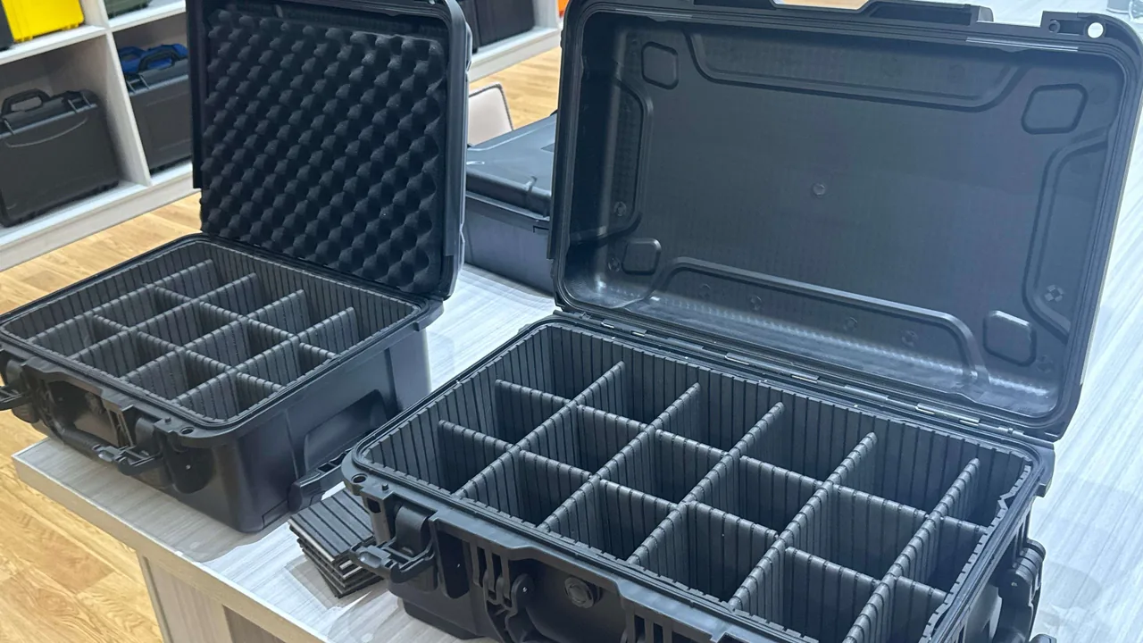
Aquaculture is moving from feeding by intuition to feeding by data. In a recirculating aquaculture system, an automatic feeder drops pellets on a preset schedule, a dissolved oxygen sensor reports a reading every thirty seconds, pH and temperature probes trigger the aerators, and cameras and sonar on a cage platform translate feeding intensity into the next ration. What all these devices share is a contradiction: they are expensive, yet they live permanently in hot, humid, salt-laden and vibration-heavy conditions at the water's edge. Once they take on water, absorb moisture or suffer an impact during relocation, maintenance, seasonal migration or export shipment, the cost is rarely just a repair invoice. It is an interrupted feeding cycle and a water quality parameter that has drifted out of control.
JUNZHIJIA's position is that protecting aquaculture equipment is never a matter of throwing a box around a machine. It is a systematic design exercise spanning sealing level, cushioning structure, anti-corrosion treatment and compartment layout, so that salt spray, water vapor, condensation and vibration are all isolated at the moment of packing rather than discovered on site.
This article is written for equipment managers at farming operations, export packaging engineers at aquaculture equipment manufacturers, and technical buyers responsible for farm consumables. It breaks down the protection methods for automatic feeders, water quality monitoring controllers, dissolved oxygen, pH and temperature probes, and cage-side electrical components, and provides selection tables and acceptance criteria that can be quoted directly.
Table of Contents
- 1. Four Environmental Risks Facing Aquaculture Equipment
- 2. Automatic Feeder Structures and Their Protection Needs
- 3. Water Quality Monitoring Controllers and Sensors
- 4. Transport Risks for Dissolved Oxygen, pH and Temperature Probes
- 5. Salt-Spray Corrosion in Marine Farming Environments
- 6. Water Sealing and IP Rating Design
- 7. Condensation, Humidity and Desiccant Strategy
- 8. Shock, Vibration and Foam Liner Design
- 9. Handling Protection for Cage and Offshore Platform Equipment
- 10. Compartments, Dividers and Accessory Management
- 11. Selection Parameters and Acceptance Criteria
- 12. Customization, OEM/ODM and Tooling Services
- Frequently Asked Questions FAQ
- Conclusion and Related Reading
1. Four Environmental Risks Facing Aquaculture Equipment
The failure modes of aquaculture equipment differ from those of ordinary industrial machinery, because the equipment sits at the boundary between water, electricity and salt. Broken down, the risk comes from four directions.
| Risk category | Typical trigger | Direct consequence | Protection direction |
|---|---|---|---|
| --- | --- | --- | --- |
| Liquid water ingress | Deck spray, rain, washdown guns, bilge water | Board shorts, seized relays, fogged displays | IP65 or better sealing, compressed gaskets, drainage geometry |
| Vapor and condensation | Large day-night swings, repeated cold store to sun exposure | Oxidized contacts, fogged optics, blurred lenses | Desiccant, breather valve, anti-condensation liner |
| Salt-spray corrosion | Offshore cages, coastal ponds, vessel-mounted gear | White rust on aluminum, seized threads, rising contact resistance | Material selection, salt-spray validation, surface treatment |
| Shock and vibration | Lifting, sea transport, mountain roads, manual drops | Sensor zero drift, displaced optics, cracked solder joints | Foam cushioning, compartmentalized fixturing, stacking design |
Farming sites seldom have climate-controlled warehouses, and a device may go through four or more relocations a year as it moves from buffer stock to installation, to service, and back into storage at season end. Every relocation is a complete transport event. Without a dedicated case, the device itself absorbs loads that packaging was supposed to absorb. This is precisely why, in both deep-water cage and recirculating system farming, equipment makers increasingly deliver a protective case as a standard accessory rather than an afterthought.
2. Automatic Feeder Structures and Their Protection Needs
An automatic feeder typically consists of a hopper, a dispensing mechanism (auger or vibrating tray), a throwing motor, a control board, a level sensor and a solar or battery module. The protection challenge is not volume but the electromechanical mix: the same machine contains water-sensitive electronics, corrosion-prone moving metal parts and easily crushed plastic hopper walls.
- Hopper and dispensing mechanism. Hoppers are usually PP, PE or FRP with thin walls that deform under load, so the whole machine weight must not rest on the hopper wall. The auger shaft is a slender part that can bend slightly under sustained vibration and then jam the feed path. During packing, the hopper is best inverted or laid on its side, supported at the mouth by EVA blocks.
- Throwing motor and gearbox. The bearing at the motor shaft end is sensitive to axial impact. A cushioning layer of at least 30 mm under the machine base is advisable. If the complete unit exceeds 25 kg, the compression set of that layer should stay below 10 percent.
- Control and driver boards. Boards fear moisture and static. Relative humidity inside the case should be kept below 45 percent, boards should travel inside anti-static bags, and the case itself should offer ESD protection so that friction-generated charge does not discharge through the connectors.
- Battery module. Lead-acid or lithium packs should occupy a separate compartment to prevent leakage from contaminating other parts and to prevent metal tools from bridging the terminals. Lithium cells must also satisfy UN38.3 transport provisions.
- Solar panel and bracket. Glass panels need rigid support and must not be supported only by point contact with foam, or localized stress will cause micro-cracks.
For complete-machine exports, split the feeder into three packing units: electrical enclosure, hopper, and throwing assembly. The electrical enclosure travels in a high-protection case, while the hopper and throwing assembly use structural cushioning. Even if a sea voyage brings prolonged humidity, only the electrical portion then requires expensive protection.
3. Water Quality Monitoring Controllers and Sensors
Water quality monitoring underpins every farming decision. A typical online controller integrates dissolved oxygen, pH, temperature, ammonia nitrogen and conductivity channels, connects several external probes, and houses an analog front end, an isolated power supply and a wireless or cellular module inside its enclosure. Protection for such a device follows three lines: sealing, isolation and restraint.
- Sealing. The controller enclosure may itself be IP65 or IP66, but the transport case still needs independent protection. Vibration in transit makes the enclosure gasket micro-move, and stacking loads can distort the housing and destroy flatness. The transport case must supply a rigid outer shell that isolates the controller from stacking force.
- Isolation. Probes normally connect through waterproof connectors. During transport, remove the probes and stow them in separate compartments so that cables are not repeatedly flexed and broken internally. Protect connector faces with caps against salt spray and dust.
- Restraint. Any pluggable module inside the controller, such as a cellular modem, SD card or calibration chip, should be secured against loosening. Molded foam can fixture the controller on all six faces, with total travel in any direction held under 3 mm.
Water quality instruments are often paired with dosing and aeration actuators, and their required protection level follows directly from the installation environment. If you also manage process instruments, the sealing and anti-corrosion approach in Water Treatment Instrument Cases: Sealing and Corrosion Protection applies the same wet-side and dry-side zoning logic used in aquaculture monitoring.
4. Transport Risks for Dissolved Oxygen, pH and Temperature Probes
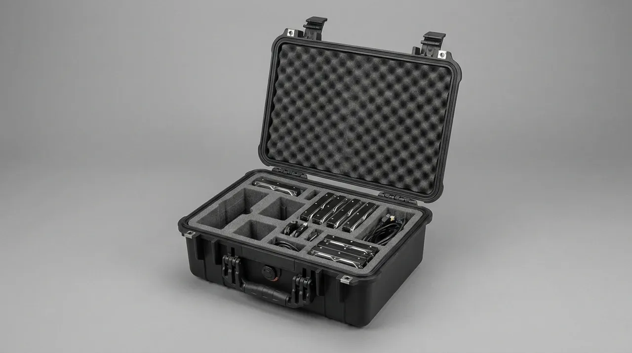
Probes are the most delicate part of any system and the component with the highest transport damage rate. They share three traits: a sensing face made of a sensitive membrane or glass electrode, a high-impedance signal path, and a slender mechanical body.
| Probe type | Sensitive area | Main transport risk | Recommended protection |
|---|---|---|---|
| --- | --- | --- | --- |
| Optical dissolved oxygen | Fluorescent membrane, optical window | Membrane scratches, optical misalignment, membrane aging | Protective cap, stored upright, no contact with hard parts |
| Polarographic dissolved oxygen | Permeable membrane, electrolyte | Electrolyte drying, membrane rupture, trapped bubbles | Keep in storage solution, transport upright, never inverted |
| Glass pH electrode | Glass bulb, liquid junction | Bulb fracture, reference loss, junction clogging | Soak in KCl storage solution, molded foam cradle |
| Temperature probe (Pt100/NTC) | Sensing element, lead wires | Broken strands from pulling, deformed tip under pressure | Coil cables at large radius, tie down at the connector |
| Ammonia or conductivity electrode | Plates, plated coatings | Coating wear, contamination of chemically sensitive face | Sealed individual bag, never share a cavity with metal |
Three practical rules deserve emphasis. First, any probe holding a storage solution must never be inverted in transit, or the solution can run into the terminal cavity and cause leakage current. Second, the minimum bend radius of probe cable should not fall below eight times the cable diameter, otherwise long-term storage produces hidden broken strands. Third, never mix probe materials in the same compartment; a glass electrode sharing a cavity with a metal wrench is a classic transport accident. For the wider principles behind these choices, see Sensor Transport Cases: Compartment and Cushioning Design.
5. Salt-Spray Corrosion in Marine Farming Environments
Equipment on offshore cages, tidal flats and coastal ponds lives in a permanently saline atmosphere. The damage is progressive: first white corrosion spots on aluminum, then seized threads and rising connector resistance, and finally reduced structural strength and failed sealing faces. Protection during transport and storage is essentially buying a safe buffer period before the equipment ever enters the sea.
The common material and corrosion pairings are worth memorizing:
- Plain carbon steel shows visible red rust within weeks in coastal open air and should never be exposed unpainted.
- Zinc-plated parts show white rust early, but structural loss is slow. White rust should be wiped off and the coating touched up promptly.
- Aluminum and its alloys pit readily in marine atmospheres, especially at high chloride concentration, and need anodizing or coating.
- Type 304 stainless steel can suffer pitting and stress corrosion cracking in chloride environments, so 316 or 316L is preferred for high-salinity coastal duty.
- Engineering plastics such as PP, ABS, PC and PA resist salt spray inherently, but UV aging and low-temperature embrittlement must still be considered together.
Because corrosion is a function of time multiplied by environment, validating a protection scheme requires more than reading a material grade; it requires accelerated verification. The duration and judgement rules are set out in Salt Spray Corrosion Testing: Duration and Pass Criteria for Cases. For exported farming equipment, attaching a salt spray report to the shipping documents substantially reduces customer complaints that a unit rusted within two years.
6. Water Sealing and IP Rating Design
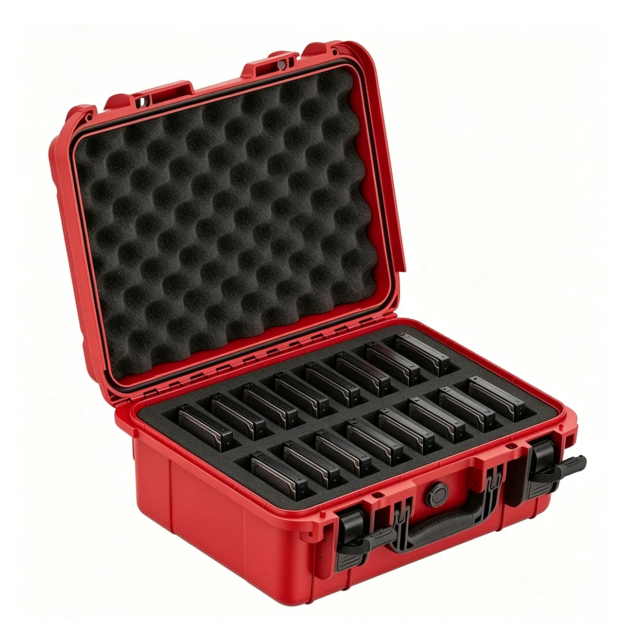
A case's water resistance is decided by its structure, not by its marketing copy. What actually determines the rating is the gasket cross-section and compression ratio, the flatness of the parting line, the clamping force delivered by the latches, and the rigidity of the hinge side. The IP definitions commonly cited in the industry come from IEC 60529 and GB/T 4208, and IP65 (water jets), IP66 (powerful water jets) and IP67 (temporary immersion) serve different purposes in aquaculture logistics.
| Transport or storage scenario | Suggested rating | Notes |
|---|---|---|
| --- | --- | --- |
| Indoor workshop transfer, temporary storage | IP54 / IP65 | Dust first; occasional splash tolerated |
| Short open-air storage at a coastal site | IP65 / IP66 | Must tolerate rain and washdown |
| Deck handling with fall-overboard risk | IP67 | Temporary immersion without ingress; buoyancy helps |
| High-pressure washdown zone | IP69K | Hot high-pressure jets need special sealing |
Three details are frequently overlooked. The first is compression ratio: a gasket is normally flattened by 20 to 30 percent. Too little and it does not seal; too much and it takes a permanent set and its service life collapses. The second is pressure equalization. A sealed case transported by air or across a steep thermal gradient develops a pressure differential; if the case is perfectly sealed, it becomes hard to open and the gasket can be drawn inward. A breathable waterproof vent, either a membrane type or a labyrinth design, is the established solution, and the selection logic is covered in Pressure Equalization Valves for Protective Cases. The third is parting-line rigidity: if the case mouth warps under latch load, the best gasket in the world fails. Adequate ribs and wall thickness are therefore structural requirements, not cosmetic ones. For a full treatment of outdoor sealing architecture, see Outdoor Case Waterproof Design Essentials.
7. Condensation, Humidity and Desiccant Strategy
Much of what is reported as water ingress is actually condensation. A device baked in the sun by day and cooled by sea breeze at night will precipitate moisture from the trapped air onto whichever metal surface is coldest. For water quality controller boards and optical sensors, liquid intrusion matters, but vapor intrusion is harder to stop and far more insidious.
Humidity control works on four levels:
- Reduce the starting humidity. Confirm that both the equipment and the foam are dry before packing, and avoid packing during rain or in the humid early morning.
- Block exchange. IP sealing reduces, but never eliminates, vapor exchange with the outside atmosphere; over long storage there is always slow permeation.
- Absorb actively. Size desiccant to the internal volume. A rough rule is 50 to 100 g of silica gel per 0.05 cubic meters, with a humidity indicator used to decide when to replace it.
- Indicate. Place a reversible humidity indicator card inside the case and read it at every opening. This is far more reliable than judging by feel.
Dissolved oxygen probes and pH electrodes need a nuance. Electrical and optical parts want the case as dry as possible, while electrodes in storage solution must stay wet. The practical answer is zone management inside one case: a dry zone for electronics and optics, a wet zone for solution-filled probes, and a sealed divider between them so the two humidity targets do not fight each other.
8. Shock, Vibration and Foam Liner Design
The typical transport damage to aquaculture equipment is not a broken shell but a loosened assembly. Prolonged low-frequency vibration backs out screws, wears connectors through micro-motion, and shifts sensor zero points. The core of cushioning design is to create an energy-dissipating layer between the device and the case wall while eliminating free movement inside the case.
Material trade-offs are summarized below.
| Material | Cushioning | Resilience | Moisture resistance | Typical use |
|---|---|---|---|---|
| --- | --- | --- | --- | --- |
| EPE (expanded polyethylene) | Good | Medium | Good | Hoppers, housings, large supports |
| EVA | Good | Good | Good | Precision probes, molded cradles |
| PE foam | Medium | Medium | Good | General filling and underlay |
| IXPE | Good | Medium | Good | Thin-wall parts, surface protection |
| PU sponge | Good | Good | Poor | Surface protection with moisture treatment |
Two quantified rules govern the design. First, travel control: the device must not move more than 3 mm in any direction inside the case. Second, drop redundancy: match the required drop height to the packed weight, because heavier packages are allowed lower drop heights. For vibration and resonance verification methods, including sweep testing logic, see Transport Vibration and Resonance Verification.
9. Handling Protection for Cage and Offshore Platform Equipment
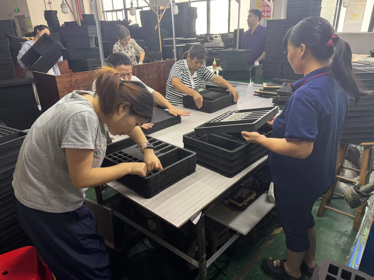
Loading and unloading equipment on a deep-water cage platform is the most demanding link in the whole supply chain. Lifting, vessel transport, temporary deck storage and manual handling occur side by side, and the case must withstand salt spray, wave splash and sling compression simultaneously. Here the design emphasis shifts from preventing water entry to resisting mechanical damage.
- Lifting load points. If a case will be lifted, the load must land on primary structural ribs and never on the shell alone. Provide lifting apertures or reinforced blocks so that ropes do not bite into the corners.
- Stacking capacity. Deck space is tight and cases get stacked. The lid should carry locating grooves for stacking, and the base load at the maximum stacked height must be verified. Foam under permanent compression takes a compression set, so heavy cases belong at the bottom.
- Anti-slip and drainage. Deck surfaces are wet, so the base needs anti-slip pads and should stand clear of standing water.
- Marking. Lifting orientation, center of gravity and this-side-up markings must survive seawater immersion without peeling.
- Associated electrical parts. Junction boxes, inverters and communication modules sharing a case must occupy separate compartments to prevent interference.
The long-term protection thinking for offshore platform equipment overlaps heavily with Marine Buoy Instrument Cases: Weather-Resistant Design, particularly in watertight connectors, anti-fouling measures and weathering coatings.
10. Compartments, Dividers and Accessory Management
Aquaculture equipment comes with a wide, oddly shaped accessory set: wrenches, clamps, cables, spare probes, gaskets, manuals and calibration fluids. Mixed packing looks space-efficient, but it is a hidden tax on transport survival and on-site installation efficiency. Compartmentalization pays off in three ways.
First, physical isolation. A metal tool sharing a cavity with a glass electrode is effectively scheduling a free-fall experiment for the probe. A removable divider between the tool bay and the instrument bay is the cheapest risk control available.
Second, counting efficiency. Farm installation sites rarely have a proper workbench. When accessories are loose in one pile, finding a single item means emptying the whole case. With functional compartments, the installer opens the case and takes items in sequence, and installation time usually shortens noticeably.
Third, condition management. Fixing what belongs in each compartment, reinforced by labels, builds a long-term habit of noticing a missing item immediately. For farms rotating several sets of equipment, this directly determines equipment availability.
In layout terms, follow four rules: heavy items low, hard items inboard and soft items outboard, liquid-bearing items isolated, and tools in their own bay. Put the heavier motor and battery in the lower part of the case, cradle precision probes in the middle with molded foam, seal solution-filled probes separately, and route tools and cables into a dedicated accessory compartment or a lid organizer.
11. Selection Parameters and Acceptance Criteria
Consolidating the concerns above into one table lets procurement and equipment management speak the same language.
| Parameter | Recommended value | Notes |
|---|---|---|
| --- | --- | --- |
| Outer shell material | PP, ABS, PC or modified engineering plastic | Coastal duty favors salt-spray and UV resistant grades |
| Protection rating | IP65 minimum, IP67 for deck duty | Verify against a third-party report |
| Wall thickness | 2.5 to 4 mm, thicker at ribs | Must match stacking load |
| Gasket | Silicone or EPDM | Watch compression set and weathering |
| Cushioning layer | EVA or EPE, at least 30 mm | Thicker as weight rises |
| Pressure equalization | Breathable waterproof vent | Essential for air freight and thermal cycling |
| Operating temperature | Minus 20 C to plus 60 C | Must cover sun-exposed deck temperature |
| Stacking capacity | Calculated from actual stack height | Requires a full-load static test |
| Latches and hinges | Cycle-life tested | Track opening count and clamping force decay |
| Shipping documents | Certificate, test reports, packing list | Export units should include salt spray and drop reports |
Acceptance criteria should include at least four checks: appearance and structure (no cracks, no deformation, complete ribs); sealing performance against the target IP rating; liner fit (travel under 3 mm with no hard spots); and document completeness including material certificates, test reports and packing list. For tenders and bulk procurement, the technical agreement should also state the acceptance method and the rule for judging nonconformity. Clause wording is discussed in Writing Tender Specifications for Protective Cases.
12. Customization, OEM/ODM and Tooling Services
Aquaculture equipment shapes vary enormously: one feeder has a cylindrical hopper, one water quality controller is a flat rack-mount unit, and one probe set is a bundle of slender rods. A standard case rarely fits exactly, and exact fit is precisely what determines protection. Too loose and the equipment vibrates; too tight and assembly is difficult and sensitive parts are crushed.
Custom protective cases typically offer the following options:
- Custom liner. CNC-cut EVA or EPE matched to the three-dimensional equipment model, with molded foam and snap features for precision probes.
- Form and structure. Adjust height, add tiers, fit handles or wheels on an existing tool, or cut a new mold for unusual dimensions.
- Sealing level customization. Adapt gasket structure and test level for deck and submerged duty.
- Marking and color. Screen-printed logos, heat-transfer branding and color matching to a farm's visual standards for on-site asset identification.
- Shipping documents. Certificate of conformity, material and test reports, packing list, and installation and maintenance instructions, with multilingual versions for export.
There are three common OEM and ODM models: pure OEM manufacturing to the customer's drawing under the customer's brand; joint design, where the customer supplies operating conditions and the manufacturer returns a structure and liner proposal; and full ODM, where the manufacturer offers a mature case and liner and the customer applies its own brand. Whichever model is chosen, the contract should state drawing ownership, tooling ownership and acceptance standards to avoid disputes at mass production.
A typical tooling process runs through seven stages: requirement and operating-condition review, structure and liner design, 3D printed or rapid sample validation, mold design and manufacture, trial molding and first-article inspection, small-batch pilot production, and mass production. For a first collaboration, the most under-estimated stage is sample validation. Problems such as probe cradle interference, excessive lid closing force and poorly placed handles only show up on a physical part, and validating early substantially reduces rework cost and schedule risk later. If you also need a complete transfer solution for fishing and vessel equipment, Fishing and Marine Gear Cases shows how the modules combine. JUNZHIJIA supplies custom liners, structural modification, tooling, OEM and ODM programs and shipping documentation for automatic feeders, water quality controllers, and dissolved oxygen or pH probe sets.
Frequently Asked Questions FAQ
Q: For a complete automatic feeder, should we keep the original factory packaging or switch to a protective case?
A: It depends on the length and severity of the logistics chain. For a short road leg from factory to distributor, original foam and a carton are usually sufficient. But as soon as sea freight, multiple transshipments, open coastal storage or seasonal recovery are involved, upgrade to a case with sealing and cushioning. The reason is that factory packaging is usually designed to be single-trip and disposable, while farming equipment logistics are multi-trip, reversible and continuous. Reduce the decision to three questions: must salt spray and moisture be kept out, must repeated lifting and drops be resisted, and must the unit sit outdoors for long periods? If any two answers are yes, move to an engineered case and split the hopper, throwing assembly and electrical enclosure into separate packing units so the total weight is distributed across several cases. As a practical benchmark, any unit that will be handled more than twice by crane or forklift, or that will sit outdoors for more than a month, should be treated as an engineered case application from the start, with a written packing method and a defined repacking procedure for the return leg.
Q: What most commonly damages the fluorescent membrane of a dissolved oxygen sensor in transit?
A: Three factors usually combine. The first is physical abrasion, where the membrane touches a hard tool, a metal clamp or the case wall; even light rubbing leaves a permanent scratch that shifts the reading. The second is optical misalignment, as internal optical components shift under sustained vibration, showing up as calibration drift or a slower response. The third is accelerated membrane aging, where high temperature, high humidity and ultraviolet exposure all shorten fluorescent membrane life. The correct approach is to fit each sensor with a dedicated protective cap, use a molded single-unit cradle so the membrane touches nothing hard, and keep the case out of direct sunlight for extended periods. After opening, run a zero and slope check before returning the sensor to service, and only deploy it once the reading is stable. It also helps to log the serial number and calibration date of every sensor before dispatch, so that any drift discovered on arrival can be traced to transport rather than blamed on the instrument, which keeps warranty conversations factual.
Q: Why must a glass pH electrode be transported upright and kept wet?
A: A pH glass electrode measures through a hydrated gel layer on the surface of the glass bulb. Once that layer dries out it stops functioning, and it takes prolonged soaking to recover even partially; in severe cases the change is irreversible. At the same time, a liquid junction separates the bulb interior from the reference chamber, and if the electrode is inverted in transit the reference electrolyte can escape or mix with the internal solution, causing reference potential drift. The correct practice is to store the electrode upright in 3 mol/L potassium chloride storage solution, use a dedicated cradle so the bulb is never loaded, keep transport temperature between 5 and 40 C, and avoid freezing. During long storage, check the storage solution level periodically, top it up when low, inspect the junction for crystal blockage, and soak it in warm water to clear the junction before use. Never store a dry electrode as a spare without protection, because a dried bulb is effectively a dead spare by the time it is needed.
Q: Should an aquaculture equipment case be IP65 or IP67?
A: The deciding question is whether brief immersion is realistically possible, not whether a higher number sounds better. IP65 withstands water jets, such as washdown or driving rain, and suits workshop transfer and sheltered storage. IP67 withstands temporary immersion at a specified depth and time, and suits deck handling, vessel transport and work where a unit might fall overboard. Note that IP67 does not automatically mean longer life. Its gasket normally sits at a higher compression ratio, so the seal is under greater deformation continuously and, if maintenance is poor, may actually age faster. For most coastal farms, where equipment spends most of its time in a covered store, IP65 with desiccant and a well-designed liner is often more practical than an unmaintained IP67. Only equipment that genuinely goes aboard a vessel or onto a deck justifies the cost of IP67, and then the supplier should provide a matching third-party test report. It is also worth remembering that an IP67 case must still be opened periodically for inspection, because a gasket that is never examined cannot be assumed to be intact.
Q: How much desiccant should go inside the case, and how often should it be replaced?
A: Estimate from internal volume and expected storage duration. A rough rule is 50 to 100 grams of silica gel per 0.05 cubic meters of internal volume, taking the upper figure in humid conditions and for longer storage. That number is only a starting point. The real method is closed-loop management with a humidity indicator card: place a reversible card inside, mark the threshold color zone, read it at every opening, and if the reading has crossed the line, replace the desiccant and inspect the seal. There is no universal replacement interval. In a wet season it may be monthly, while in a dry season three months or more may be acceptable. Another commonly missed point is judging saturation. Most silica gel changes color as it absorbs, but some formulations change only slightly, so weigh the sachet against its initial weight and treat a defined percentage gain as end of life. Whichever method is used, record the desiccant weight, the indicator reading and the replacement date on a label inside the lid so the next inspection has a baseline.
Q: How do we prevent and diagnose hidden broken strands in probe cables?
A: Hidden broken strands look intact and may even pass a continuity test intermittently, yet during operation they cause intermittent signal loss under vibration or thermal drift, which makes them very hard to trace. Prevention depends on controlling bend radius and fixation. The minimum bend radius should be at least eight times the cable diameter, cables should be coiled in large loops rather than folded sharply, and the connector should be tied down so stress does not concentrate at the solder joint. Cables must not be crushed by the lid or share a cavity with hard tools. For diagnosis, test each conductor with a multimeter while gently flexing the cable and watching for a jump in reading. For high-impedance signal lines, a more reliable approach is to monitor data fluctuation with the device powered while applying vibration, so the fault is reproduced under load. Recording each cable before and after transport allows a fast comparison. Keep a spare cable in the accessory bay as well, so a suspect run can be swapped out on site without pulling the whole installation apart.
Q: In a salt-spray environment, how should the case material be selected?
A: The first rule is to avoid bare carbon steel and 304 stainless steel structural parts in marine atmospheres. Prefer salt-spray modified engineering plastics such as weather-resistant PP, ABS or PC, which do not undergo electrochemical corrosion and whose outdoor life can be extended with UV stabilizers. Fasteners, latches and hinges should use 316 or 316L stainless steel or an appropriately plated finish, and galvanic corrosion at dissimilar metal joints must be considered. If a metal frame is unavoidable, anodize or coat it and avoid coating damage. Once the material is chosen, do not rely on the material certificate alone. Run salt spray acceleration testing, correlate the test duration with the intended exposure years, and state the inspection and maintenance interval in the shipping documents so the customer knows what to check. Where possible, review that interval after the first two years of service and shorten it if inspection finds early corrosion, because coastal conditions vary far more between sites than any catalogue figure suggests. Document the tests you run as well, so the records can support a warranty discussion if one is ever needed.
Q: What stages does a custom protective case go through from requirement to mass production?
A: The standard process has seven stages. First, confirm requirements and operating conditions, including equipment size and weight, transport mode, storage environment and target protection rating. Second, design the structure and liner, producing a drawing set and a three-dimensional model. Third, validate a sample through 3D printing or a hand-built prototype to confirm fit and cushioning. Fourth, design and manufacture the mold, which can be skipped if an existing case tool is reused. Fifth, trial molding and first-article inspection covering dimensions, sealing and appearance. Sixth, pilot production with drop, vibration and immersion validation. Seventh, mass production and delivery. For a first-time partner, the most under-estimated stage is sample validation, because issues such as probe cradle interference, excessive lid closing force and poor handle placement only appear on a physical part, and resolving them early sharply reduces rework cost and schedule risk.
Conclusion and Related Reading
Aquaculture equipment is only worth what it delivers while online. Getting sealing, cushioning, corrosion resistance and compartment design right at packing time is the cheapest insurance a farm can buy.
Related Reading