

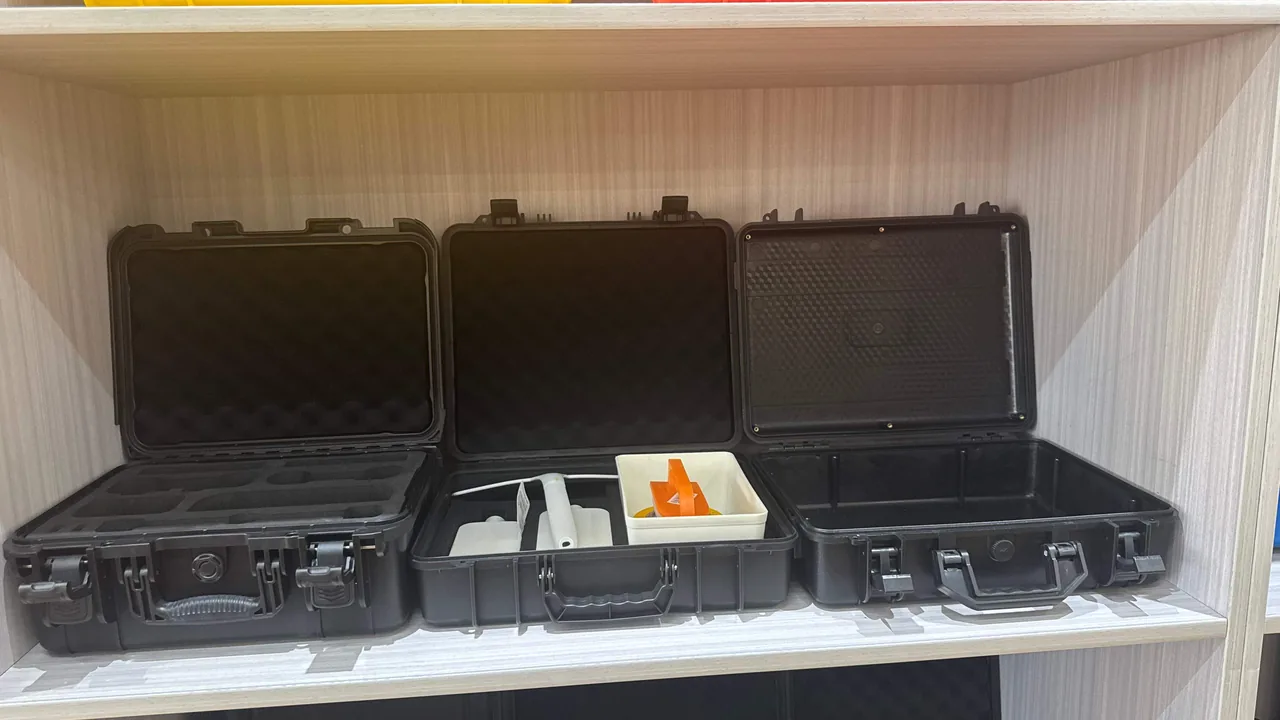
Biogas plants rarely sit in clean industrial parks. They cluster around livestock farms, municipal wastewater works, landfill cells and agricultural waste depots, so every skid and module leaves the workshop on a long highway run before it is unloaded onto a muddy yard and left waiting for the civil works to catch up. A desulfurizer media tray, a fiberglass shell flange, a long agitator shaft coupled to a gearbox, and the delicate internals of a gas-water separator share one uncomfortable property: they are large, non-standard and expensive to replace, and their mating surfaces tolerate far less abuse than the trip will deliver. The JUNZHIJIA protection principle is simple: corrosion, moisture, shock and stacking must be solved inside a single case at the factory, not improvised at the site.
This article walks the full biogas chain, from desulfurization and digester agitation to gas-water separation and boosting, and breaks each equipment family down into its real failure modes. From there we set out the case materials, sealing levels, cushion builds, compartment logic, latch selection and test evidence that turn transport protection into a specification item an engineer can accept, rather than a packaging gamble nobody can verify.
Table of Contents
- Why Biogas Plant Equipment Resists Ordinary Packaging
- Desulfurization Skids: Packing Media Trays, Shell Flanges and Analyzers
- Agitators and Gearboxes: Protecting Long Shafts and Seal Faces
- Gas-Water Separators and Blowers: Guarding Precision Mating Surfaces
- Case Materials That Survive Hydrogen Sulfide and Salt
- Moisture, Condensation and the Right Desiccant Strategy
- Cushioning: EPE, EVA, IXPE and Composite Liner Builds
- Compartment Layout and Part Retention
- Latches, Hinges and Pressure Equalization Valves
- Stacking, Pallet Planning and Load Distribution
- Transport Testing and Acceptance Criteria
- Custom Tooling and OEM/ODM Delivery
- Frequently Asked Questions FAQ
- Conclusion and Related Reading
Why Biogas Plant Equipment Resists Ordinary Packaging
A biogas plant is a wet, mildly acidic, high-humidity environment. Feedstock ranges from pig and dairy slurry to food waste, straw and high-strength organic effluent, and anaerobic digestion produces raw gas carrying 50-70 percent methane, 30-45 percent carbon dioxide, and hydrogen sulfide that can run anywhere from 500 to 5,000 ppm. Ammonia, siloxanes and water vapor are frequent companions. Metal components live in a low-pH, sulfur-bearing, damp atmosphere where stainless steel is not automatically maintenance-free: chloride stress corrosion, pitting and galvanic attack all concentrate at welds, threads and crevices.
The logistics of a biogas build add three more problems. First, delivery is usually a one-off complete set: a 500 kW gas engine project may ship a desulfurizer tower, agitators, a gas-water separator, a roots blower, a compressor and control cabinets together, often more than a hundred parts, many of them custom and with no spare on any shelf. Second, the last leg is rough: the final five to twenty kilometers are frequently unpaved, mixing potholes with standing water. Third, storage is long: equipment often sits outdoors or under a light shelter for weeks or months before pipework is ready, and that waiting period is where moisture and thermal cycling do their quiet damage. Together these conditions demand a case that is simultaneously impact-resistant, moisture-resistant, corrosion-resistant, stackable and durable across many open-close cycles.
Our field reviews of transport damage show a consistent pattern: media trays that collapsed at the edges under stacking, agitator shafts bent at mid-span because nothing supported them, glass level gauges shattered inside the case, and blower pulleys seized after water entered the packaging. None of these are bad luck. Each is a missing calculation in the protection design.
Desulfurization Skids: Packing Media Trays, Shell Flanges and Analyzers
Biogas desulfurization divides into dry and wet routes. Dry towers hold iron-oxide or activated-carbon media as pellets or extruded shapes, and a single tower can carry several hundred kilograms of media. Wet systems circulate a chelated-iron solution through pumps, oxidation blowers and spray layers. Both have their own weak points in transit.
Media and trays suffer most from stacking compression and moisture caking. Iron-oxide media loses strength once it absorbs water, and vibration then breaks it down; a powder fraction above roughly five percent usually forces top-up or a full media change. Trays are commonly stainless or FRP grating with limited edge stiffness, so they collapse at the rim when stacked directly. Give each tray its own cavity with 15-25 mm of clearance around the perimeter, and support it from underneath with EVA blocks rather than loading the grating face.
Shell flanges, whether fiberglass or carbon steel, are the sealing interface. A dent or deep scratch on a flange face may need re-machining on site, where no lathe exists. Fit wooden or PE protection rings on both sides and wrap the flange in foam so it cannot touch the case wall. If the tower already carries internal gas distribution pipes or spray headers, add temporary internal bracing so a cantilever cannot swing against the shell during vibration.
Inline instruments such as pressure transmitters, temperature probes, H2S analyzers and flow meters are small, costly and fragile. Ship them segregated in an upper compartment, never in the tower cavity. Coil and restrain capillaries and cable tails, cap every connector against mud and water, and keep the transmitter diaphragm away from any hard surface.
The table below maps the common failure modes of a desulfurization package to the measures that prevent them.
| Component | Typical failure mode | Trigger | Protective measure | Acceptance criterion |
|---|---|---|---|---|
| --- | --- | --- | --- | --- |
| Media tray | Collapsed rim, deformed grating | Stacking, drop | Dedicated cavity + EVA edge support | Flatness deviation no more than 2 mm/m |
| Iron-oxide media | Caking, dusting | Moisture ingress, vibration | Foil vacuum bag + desiccant | Dust fraction no more than 3 percent on opening |
| Shell flange | Dents, scratches | Hard contact with case | PE protection ring + foam wrap | No visible marks on sealing face |
| Spray header | Cantilever distortion | Transport resonance | Temporary internal bracing | Straightness deviation no more than 3 mm/m |
| Analyzer probe | Broken glass, damaged diaphragm | Collision inside case | Segregated upper compartment + foam | Intact, within calibration tolerance |
| Cable connectors | Mud ingress, oxidation | Water entry | Dust caps + desiccant | IP67 re-test passes |
Wet desulfurization auxiliaries such as circulation pumps and oxidation blowers follow the same logic as industrial water treatment hardware, so the protection approach in our guide to water treatment equipment cases can be combined with the layouts described here. Sludge-handling equipment that shares the same wet, abrasive duty can be approached in the same way as sludge dewatering cases.
Agitators and Gearboxes: Protecting Long Shafts and Seal Faces
The digester agitator is among the riskiest items in any biogas shipment. Configurations include side-entry mixers, top-entry long-shaft units and submersible mixers. A top-entry shaft can be six to twelve meters long, a classic slender flexible body with a low natural frequency. Highway excitation in the three-to-fifteen-hertz band easily drives it into resonance, and the result is mid-span plastic bending, mechanical seal face misalignment and coupling distortion.
For a long shaft the central idea is to change the support condition and convert a cantilever into a multi-support beam. Fit at least three axial cradles inside the case, spaced no more than one third of the shaft length apart, each lined with EVA or rubber so it both supports and damps. Clamp the end flanges with limit blocks to stop axial travel, and add longitudinal stiffeners along the case so the shaft weight and any shock load travel into the primary structure. Above four meters, split the shipment and join on site, or combine a steel transport frame with a protective enclosure.
Side-entry mixers fail at the mechanical seal and gearbox output shaft. Seal faces are flat to microns, and any axial shock can chip an edge and start a leak. Gearbox damage usually comes from oil sloshing violently plus radial load on the output shaft. Pack the mechanical seal in a dedicated EVA box, or wrap the gearbox end in corrugated board and foam and restrain it heavily. Check the oil level and the breather before shipping, and bolt the whole assembly to wooden skids or steel rails cast into the case floor; never let it float on straps alone.
Submersible mixers are compact and dense, so the threats are impeller deformation and damage to the cable gland. Ring the impeller with an EVA locating block, coil the cable at a bend radius of at least ten times its diameter, and keep all load off the gland.
| Equipment type | Primary risk | Key protection | Case structure |
|---|---|---|---|
| --- | --- | --- | --- |
| Top-entry long-shaft agitator | Shaft resonance, seal misalignment | Three or more cradles + EVA + end limit blocks | Extended case + longitudinal ribs |
| Side-entry mixer | Seal chipping, oil loss | Dedicated seal box, oil check, floor rails | Compartmented case + vertical bracing |
| Submersible mixer | Impeller deformation, gland damage | Ring locator, large-radius cable coil | Single-part cavity |
| Gearbox | Gear shock, oil slosh | Correct oil level, intact breather, rigid fixing | Shared main cavity + floor stops |
| Couplings and fasteners | Loss, collision | Dedicated small bins + packing list seal | Upper drawer-style bins |
Gas-Water Separators and Blowers: Guarding Precision Mating Surfaces
The gas-water separator strips free water and mist from raw gas using baffles, swirl vanes or mesh demisters, while the biogas compressor or roots blower lifts gas from a few kilopascals to roughly 0.6-1.0 MPa on the way to the engine or the grid. Both share dense internal parts and precision mating surfaces that dislike shock.
A separator level instrument, whether glass tube, magnetic flap or radar, is either fragile or drift-prone. A glass gauge must be wrapped in a full foam sleeve and located independently inside the case, never resting against the shell. A magnetic flap unit needs its float secured or travel-limited with ties before shipment. A radar antenna horn must not take any load, so protect it with a soft hood. Support the shell on wooden or curved EVA saddles rather than letting the support lugs carry the weight.
For compressors and blowers, the priorities are rotor, bearings and coupling. Roots and screw rotor clearances typically run from 0.1 to 0.3 mm. Transport shock rarely causes direct rotor contact, but if the base lacks rigidity and the machine shifts on it, coupling alignment can drift out of tolerance. Bolt the machine to wood or steel rails embedded in the case floor with M12 fasteners or larger, tighten to the manual torque and mark for verification, restrain the coupling guard separately, and blank off inlet, outlet and oil ports so grit cannot enter.
Electrical and control items such as pressure switches, junction boxes and variable-frequency drives should ship in a separate case from the mechanical parts. When a package combines shells, flanges and instruments, place them in layers as described for pressure vessel component cases. Where diaphragms or elastomeric elements are involved, the fixation and temperature-control methods used for diaphragm pump cases apply directly.
Case Materials That Survive Hydrogen Sulfide and Salt
Hydrogen sulfide accompanies a biogas plant through its whole life. Dissolved in water it forms a weak acid that attacks carbon steel, zinc coatings and aluminum, and coastal or riverside projects add chlorides that drive pitting and stress corrosion together. A protective case therefore has to do two jobs: shield the equipment from mechanical damage in transit, and survive a corrosive atmosphere during long storage and site use.
Material choice depends on the role. A case for long-term outdoor storage needs UV, salt-spray and chemical resistance. A transit returnable case trades some chemical resistance for impact and stacking strength. A site tool and spares case prioritizes portability and cycle life. The table compares common materials under biogas conditions.
| Material | H2S / acid atmosphere | UV aging | Impact | Relative cost | Best role |
|---|---|---|---|---|---|
| --- | --- | --- | --- | --- | --- |
| PP (polypropylene) | Excellent | Moderate | Moderate | Low | Long storage, chemical contact |
| HDPE | Excellent | Moderate | Excellent | Low | Returnable transit, general protection |
| ABS | Moderate | Moderate | Excellent | Medium | General protection, visible parts |
| PC (polycarbonate) | Moderate | Good | Excellent | High | High strength, inspection windows |
| FRP | Excellent | Good | Moderate | High | Large shells, odd shapes |
| 304/316L stainless | Good (316L better) | Excellent | Moderate | Very high | High-value precision parts |
For cases stored near a desulfurizer we usually specify natural PP or HDPE with a UV masterbatch, and we avoid deep drainage-trapping recesses in the surface. Metal hinges and latches should be 316L or carbon steel with dacromet or hot-dip galvanizing plus a closed coating, and always galvanically isolated, because stainless touching aluminum creates a corrosion cell. Choose EPDM or silicone gaskets; nitrile hardens faster in acid atmospheres.
Do not accept a verbal claim about salt-spray performance. Sample to GB/T 10125 neutral salt spray and grade the coating and hinge corrosion after 240 to 480 hours, using the interpretation method in our note on salt spray corrosion test criteria. For coastal biogas projects, set 480 hours as the baseline and require a third-party report.
Moisture, Condensation and the Right Desiccant Strategy
On a biogas site, moisture is harder to beat than rain because it arrives three ways at once: external rainfall, internal condensation, and water carried inside the equipment itself. A case stored on site through wide day-night temperature swings expands in the warmth and contracts at night, and if it is tightly sealed with no pressure balance it draws damp air in and condenses on the inner wall at dawn. If it is not sealed, rain and splash enter directly. Both failures are common.
The remedy has three steps. First, fix the protection level. Ordinary transport protection is normally IP65, dust-tight with protection against water jets. A case needing brief immersion or washdown should be IP67. High-pressure hot washdown, as in food-waste projects, may justify IP69K. Apply IEC 60529 or GB/T 4208 for definitions and test conditions, and remember that IP67 immersion is one meter for thirty minutes, not a permanent underwater rating.
Second, design pressure equalization. A valve with a waterproof breathable membrane lets air pass slowly while blocking liquid water, which removes the suction effect that makes cases hard to open and vents the expansion pressure of a warming case. Mount the valve away from the floor, typically at mid-height on a side wall, and protect the membrane from oil and dust; our case pressure equalization valve note covers the installation rules. A balance valve is not a drain, and standing water inside a case is never acceptable.
Third, add desiccant. For cases holding media, instruments or electrical parts, place 500 to 1,000 g of silica gel or molecular sieve per cubic meter of internal volume, wrapped in breathable non-woven fabric so dust cannot reach the equipment. For long storage, add a humidity indicator card and hold relative humidity below 60 percent. If the equipment itself carries residual water, as a separator shell will, blow it dry with air and purge with nitrogen before closing.
| Storage or transit scenario | Suggested IP | Balance valve | Desiccant | Humidity target |
|---|---|---|---|---|
| --- | --- | --- | --- | --- |
| Short regional road transit | IP65 | Optional | 200-500 g/m3 | 65 percent RH or less |
| Long transit in rainy season | IP65 | Recommended | 500-800 g/m3 | 60 percent RH or less |
| Three months open yard storage | IP67 | Required | 800-1,000 g/m3 | 55 percent RH or less |
| Coastal high-salt humidity | IP67 | Required | 1,000 g/m3 + molecular sieve | 50 percent RH or less |
| High-pressure washdown | IP69K | Required | 500 g/m3 | 60 percent RH or less |
Cushioning: EPE, EVA, IXPE and Composite Liner Builds
The cushion is the second skin of the case. Its job is not simply to be soft; it has to absorb the energy of a drop or a vibration within a limited stroke so the equipment sees an acceleration peak below its allowable value. Biogas parts span a huge weight range, from a few hundred grams of instrumentation to several hundred kilograms of tower shell, so the liner must match the mass. Too hard and it offers no cushioning; too soft and it crushes and loses support.
| Material | Density (kg/m3) | Rebound | Cushion vs support | Tear resistance | Typical use |
|---|---|---|---|---|---|
| --- | --- | --- | --- | --- | --- |
| EPE | 25-35 | High | Cushion-biased | Medium | Large part wrapping, surface protection |
| EVA | 60-150 | Low, good energy absorption | Support-biased | High | Precision locating, load blocks |
| IXPE | 30-60 | Closed cell, stable | Balanced | High | Returnable liners, repeated cycles |
| PU foam | 40-120 | Wide adjustable range | Customizable | Medium | Contoured liners for odd shapes |
| Rubber/EVA composite | Not applicable | Strong damping | Support-biased | High | Long shafts, vibration-sensitive parts |
We design to a three-layer rule. The outer layer uses EPE or corrugated board for surface contact so the case wall cannot scratch the equipment. The middle layer uses EVA or PU foam for contour locating, restraining degrees of freedom by geometry. The base or load layer uses high-density EVA or rubber composite to carry weight and damp shock, spreading the load into the primary structure. For instruments and glass parts, add closed-cell IXPE for local soft wrapping.
Set drop height by mass. Common practice uses 800 mm below ten kilograms, 600 mm from ten to thirty, 400 mm from thirty to sixty, and 300 mm above sixty kilograms. The liner must not fully compact at the highest drop energy; keep at least forty percent of the original thickness remaining, or the acceleration peak climbs sharply. For slender parts such as shafts, cushioning must be paired with a support stiffness check. Additional material pairing data appears in our EPE versus EVA foam comparison and in the broader case foam material comparison.
Compartment Layout and Part Retention
The biggest hidden risk in a complete biogas shipment is mixed loading. When parts of different weight, stiffness and precision share one cavity, the heavy item acts like a hammer on the light one through every kilometer, while small parts migrate into gaps and jam. Compartmenting gives every part one defined position that is restrained in every direction.
Four rules govern the layout. Weight grading: shells, gearboxes and compressors go low and near the geometric center; instruments, probes and fasteners go high. Stiffness isolation: rigid parts and fragile parts never share a cavity, separated by dividers or a dedicated inner box. Center of gravity alignment: keep the assembled center close to the geometric center, using ballast if needed so lifting stays level. Identification: give every cavity an icon and a number matched to the packing list, so the site can count parts in and back out.
Dividers may be PP honeycomb board, EVA standing board or PVC foam board. EVA cushions well but has limited stiffness and suits light to medium parts; PP honeycomb is stiff and light and works as the primary divider; for cases opened often, a removable divider system lets the user re-plan the layout on site. Leave 10-20 mm of assembly clearance around each part to ease removal and absorb thermal movement and vibration.
For complete-set projects, supply a cavity layout drawing and a packing list showing cavity number, quantity, protection level and acceptance points for every item. On opening, count against the list, and photograph any shortage or damage immediately so claims against the carrier and insurer are supported.
Latches, Hinges and Pressure Equalization Valves
Open-close reliability determines case life. Biogas sites are harsh and operators wear gloves, so a latch must open one-handed, close with a clear feel of engagement, and stay tight over thousands of cycles. Hinges must carry the lid weight and the fatigue of frequent opening.
Latch selection rests on three numbers: retention force, cycle life and operating torque. Engineering cases commonly use elastic draw latches, rotary latches and cam latches. Elastic draw latches are simple and cheap and suit small to medium cases; rotary latches hold strongly and resist accidental opening, so they suit heavy and stackable cases; cam latches are low-effort and generate compression, which suits IP67 cases that must compress a gasket. Cycle life should be at least 1.5 times the intended open-close count, typically 5,000 to 10,000 cycles for an engineering case.
For hinges, a metal pin beats an all-plastic hinge on large lids. Use stainless or surface-treated carbon steel pins, and isolate pin from housing with a bushing to cut wear and noise. Where the lid must come fully off, a detachable hinge works, but tether the pin with a stainless lanyard so it cannot be lost.
The pressure equalization valve was covered above; here are the installation points. Keep it off the top of the lid, where it can be stepped on, and off the floor, where it can sit in water. Replace the membrane every two to three years or on any color change. If the case travels across an altitude change, from plains to a plateau project, recheck the airflow capacity or the opening suction will be uncomfortable. General valve selection rules appear in our pressure equalization valve guide.
Stacking, Pallet Planning and Load Distribution
Site space is tight, so cases are often stacked two to four high for storage. Stacking capacity comes from the compressive stiffness of the case structure, the mid-span support of the lid and the overall rigidity of the pallet, not from wall thickness alone. Blind stacking collapses lids, bulges walls and can crush the bottom case.
We verify stacking in three steps: single-case static load on the lid to check lid deflection, full-stack static load applied at the actual number of tiers to check the bottom case, and transport dynamic load, which adds the equivalent of vibration and shock on top of the static figure. Stacking tests may follow the GB/T 4857 series; a typical requirement holds the load for 24 to 72 hours with deformation inside the design limit and no permanent crush. The broader packaging test framework is summarized in our GB/T 4857 transport packaging note.
Pallet and loading practice adds a few rules. Match the pallet to the case feet and keep it inside the case footprint so a pallet corner cannot lever the case. Strap with polyester or steel banding placed clear of latches and valves. Load heavy low, large low and frequently used parts near the door, leave no gap that lets cases slide, and fill any unavoidable void with airbags or foam blocks. Mark the side wall with the center of gravity and a no-tipping symbol to guide lifting and stacking. For vibration control on complete sets, see our transport vibration testing notes.
Transport Testing and Acceptance Criteria
Reliability has to be measured, not felt. For high-value, non-standard biogas equipment with no spare on the shelf, complete four verification blocks before volume supply: vibration, drop and shock, stacking and environmental.
Vibration testing simulates sustained road excitation and matters most for shafts, cantilever pipes and instrument brackets. Run a modal check first, confirm the first natural frequency is not inside the three-to-fifteen-hertz road band, and if it cannot be moved, add supports, raise damping or change the mass distribution until the response amplitude falls inside the allowable range. Drop and shock tests validate the energy absorption of the liner and the case corners, usually with one corner, one edge and one face each. Environmental testing covers high-temperature storage, low-temperature brittleness and damp heat, verifying dimensional stability and impact resistance from minus twenty to plus sixty degrees Celsius.
Write the criteria so they bind to the contract, for example: after a 600 mm corner drop to GB/T 4857.5, the case shows no cracks, the gasket stays attached, latches function normally and the internal equipment acceleration peak stays below a stated value in g. Quantitative criteria like these are far easier to enforce at acceptance than a vague promise to meet transport requirements. A fuller read on the standards landscape appears in our transport vibration test and damping design article.
Custom Tooling and OEM/ODM Delivery
Biogas equipment is inherently non-standard. The same desulfurizer model can differ in flange elevation and nozzle orientation from one project to the next, so a protective case almost always has to be custom. The workflow runs through five stages: requirement confirmation, structural design, sample review, pilot production and volume delivery.
Requirement confirmation collects the 3D model or measured dimensions, weight and center of gravity, fragile features, expected transport environment, stacking tiers, open-close frequency and service life. Structural design produces the case assembly drawing, liner drawing, cavity layout and bill of materials, together with the design values for sealing level, stacking load and drop height. Sample review is where projects most often go wrong, so always trial-fit the real machine or an equal-weight dummy and verify removal clearance, latch torque and stacking stability. Pilot production verifies tooling and process stability, checking for sink marks, flash and color variation. Before volume delivery, sample to AQL for appearance, dimensions and sealing.
JUNZHIJIA supports a full OEM/ODM scope from case structure, liner, color and printing through to the documents that ship inside the box, including new tooling, tooling modification, logo and QR spraying, cavity layout drawings, packing lists, desiccant and humidity indicator cards. As the manufacturer, Kexin New Materials (Guangdong) Co., Ltd. keeps structural design, injection and blow molding, liner fabrication and final assembly inside one delivery chain, cutting the coordination load for assembly builders who would otherwise manage several suppliers.
Frequently Asked Questions FAQ
Q: Why can a standard wooden crate not be used to ship desulfurizer media trays?
A: Media trays are grating structures with weak edges, usually stainless or FRP, and inside a wooden crate with no dedicated locating and support, trays stack directly on each other, so stacking load and road shock concentrate at the rims and collapse the grating. Once a tray warps, the media bed no longer sits level, and gas channelling starts immediately at commissioning. The bigger problem, though, is moisture. Wood crates rarely seal reliably, and iron-oxide media loses mechanical strength quickly once it absorbs water, then dusts under sustained vibration. A powder fraction above five percent often forces a top-up or a full bed replacement, which costs far more than the case itself. The correct approach is a rigid case with each tray in its own cavity, 15 to 25 mm clearance around the perimeter, and EVA blocks supporting the grating from below rather than loading the face. Keep the media in foil vacuum bags with desiccant, hold internal humidity below 55 percent, and ship a humidity indicator card so the site can verify condition on arrival before accepting the delivery.
Q: What really causes a top-entry agitator shaft to bend during transport?
A: The cause is usually resonance rather than a single impact. A long shaft is a slender flexible body with a low natural frequency, and when the shaft length puts that frequency inside the three-to-fifteen-hertz band of road excitation, the mid-span amplitude is amplified several times. Even a modest road input can then push the shaft into plastic bending, and the damage is often invisible until coupling run-out is measured on site. The fix is to change the support condition. Fit at least three axial cradles inside the case, space them no more than one third of the shaft length apart, and line them with EVA or rubber to add damping. Clamp the end flanges with limit blocks to prevent axial travel, and add longitudinal stiffeners along the case so the load reaches the primary structure. Above four meters, split the shipment and join on site, or use a steel transport frame combined with a protective enclosure, which removes the resonance problem at its root before it can damage an expensive shaft.
Q: How should hinges and latches be specified for a hydrogen sulfide environment?
A: Hydrogen sulfide dissolves in water to form a weak acid that attacks carbon steel and zinc coatings, and coastal projects add chlorides that drive pitting and galvanic corrosion together. Specify 316L stainless steel hinges and latches, or treat carbon steel with dacromet or hot-dip galvanizing followed by a closed coating. Galvanic isolation matters even more: stainless steel must never touch aluminum directly, so add a nylon or insulating washer between them and prevent a corrosion cell from forming at the joint. Specify EPDM or silicone gaskets, because nitrile hardens and cracks faster in an acid atmosphere, and confirm that any metal insert inside the case body is fully encapsulated. Do not rely on a verbal performance claim. Sample to GB/T 10125 neutral salt spray, use 480 hours as the baseline for coastal biogas projects, and require a third-party report that grades both the coating and the hinge hardware after exposure. This turns a vague material promise into a verifiable acceptance item your project team can enforce at incoming inspection.
Q: Should a biogas plant case be rated IP65 or IP67?
A: The answer depends on the real exposure, not on choosing the highest number available. If the case only sees ordinary road transit plus indoor or light-shelter storage, IP65, meaning dust-tight with protection against water jets, is usually sufficient and keeps cost under control. If the equipment will sit outdoors on site for three months or more, or may see brief standing water and washdown, specify IP67, but note that the immersion test is one meter for thirty minutes and does not imply permanent underwater service. Only high-pressure hot washdown, as in food-waste projects, justifies IP69K. Whichever level you choose, write both the required rating and the applicable test standard into the purchase order, verify them to IEC 60529 or GB/T 4208, and check that gasket compression sits inside the design range on a production sample rather than a hand-built prototype. A printed rating and the actual sealing performance of a volume case often differ, and the gap widens as the gasket ages, so re-test after an accelerated aging cycle before approving the final design.
Q: If the case has a pressure equalization valve, is desiccant still needed?
A: Yes, because the valve and the desiccant solve different problems. The balance valve uses a waterproof breathable membrane to let air pass slowly, which equalizes pressure, removes the suction that makes a case hard to open, and vents the expansion of a warming case. It filters liquid water, but it does not remove moisture that has already entered as vapor. Desiccant works actively to absorb that vapor and lower internal relative humidity, protecting media, instruments and electrical parts from condensation. Use them together. Mount the valve at mid-height on a side wall, away from any water that could collect low in the case, and protect the membrane from oil and dust so it does not clog. Add desiccant at 500 to 1,000 grams per cubic meter of internal volume, wrapped in breathable non-woven fabric so dust cannot reach the equipment, and replace it on a fixed service interval. Remember that a balance valve is not a drain, and standing water inside any case is never acceptable for biogas hardware.
Q: Should the cushion liner be EPE or EVA foam?
A: They play different roles and are normally combined rather than chosen one over the other. EPE has low density, high rebound and low cost, which suits surface contact protection and broad wrapping so the case wall cannot scratch the equipment. EVA has higher density, lower rebound, good energy absorption and strong tear resistance, which suits contour locating and load blocks that restrain the equipment by geometry instead of by tight straps. We generally build three layers: an outer layer of EPE or corrugated board for surface protection, a middle layer of EVA or PU foam for contour locating, and a base layer of high-density EVA or rubber composite for load carrying and damping. For precision instruments and glass level gauges, add closed-cell IXPE for local soft wrapping. Set drop height by total case mass, and always confirm the liner is not fully compacted at the highest drop energy, keeping at least forty percent of the original thickness so the acceleration peak stays inside the equipment limit.
Q: How do I decide how many cases can be stacked, and can I just stack by experience?
A: No, stacking capacity must come from a load calculation and a test, not from habit. Capacity depends on the compressive stiffness of the case structure, the support across the middle of the lid and the overall rigidity of the pallet, not on wall thickness alone. We verify in three steps. Single-case static load checks lid deflection under a uniformly distributed load. Full-stack static load applies the actual number of tiers to check the bottom case. Transport dynamic load adds the equivalent of vibration and shock on top of the static figure, which is the case that matters when a truck hits a pothole at speed. Stacking tests may follow the GB/T 4857 series, typically holding the load for 24 to 72 hours with deformation inside the design limit and no permanent crush. Keep the pallet inside the case footprint, place strapping clear of latches and balance valves, leave no gap that allows sliding, and fill unavoidable voids with airbags or foam blocks before dispatch.
Q: What are the key review points from requirement to volume delivery for a custom case?
A: The chain runs through requirement confirmation, structural design, sample review, pilot production and volume delivery, and sample review is where projects most often fail, so it deserves the most time. Requirement confirmation collects the 3D model or measured dimensions, weight and center of gravity, fragile features, transport environment, stacking tiers, open-close frequency and expected service life. Structural design outputs the case assembly drawing, liner drawing, cavity layout and bill of materials, and fixes the design values for sealing level, stacking load and drop height. Sample review must trial-fit the real machine or an equal-weight dummy to verify removal clearance, latch operating torque and stacking stability. Pilot production confirms tooling and process stability and checks for sink marks, flash and color variation. Before volume delivery, sample to AQL for appearance, dimensions and sealing, so a systematic deviation is caught in the factory rather than discovered on the biogas site.
Conclusion and Related Reading
Protecting biogas equipment means converging corrosion, moisture, shock and stacking in one case design, part by part, with testable criteria, backstopped by JUNZHIJIA custom liners and OEM/ODM service.
Related Reading