

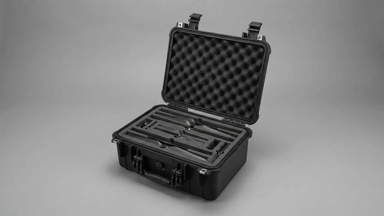
Elevator controller components never travel under ideal conditions. In the factory, a main board and a set of drive power units pass pre-assembly, burn-in and final test, then travel hundreds or even thousands of kilometres by road to project sites. On arrival they must pass through narrow machine-room corridors, up steep stairwells, and sometimes through the car top or the pit before they can be installed. Years later the same parts travel again as service replacements: an I/O board fails, a drive power module ages, an encoder interface board needs a revision upgrade. Machine-room dust, hoistway moisture, handling shock and electrostatic discharge accompany every trip, while the shutdown window available on site is often only a few hours.
JUNZHIJIA's position: a case for elevator controller components must serve two roles at once, as transport packaging and as an on-site workstation. It should survive vibration and impact on the road, then convert immediately in the machine room into a dust-sealed, moisture-controlled, reusable and traceable temporary storage container in which every board revision and every drive serial number stays clearly identifiable throughout the transfer.
Table of Contents
- Two Transfer Paths: New Installation and Service Replacement
- Board-Level and Drive-Level Failure Modes at a Glance
- Dissipative and Conductive Foam Liners: How to Use Each
- Board-Level Fragility and Connector Protection
- Bagging Practice for Shielding Bags and the Opening Sequence
- Handling the Weight and Awkward Shape of Drives and Inverters
- Machine-Room and Hoistway Logistics: Access, Lifting and Wheels
- Reusing the Case as an On-Site Container Against Machine-Room Dust
- Choosing an IP Rating: Storage Condition versus Installed Condition
- Shell Options Compared: Rotomoulded PE, Injection PP and Aluminium Frame
- Compartments, Foam Layers and Positive Location
- Labelling, Revision-Level Traceability and Travelling Documents
- Acceptance Criteria and Re-Verification Intervals
- Frequently Asked Questions FAQ
- Conclusion and Related Reading
Two Transfer Paths: New Installation and Service Replacement
New installation and service replacement impose different requirements on a protection case, and treating them as one has cost many projects dearly.
The new-installation path is typically a set shipment, batched and dispatched per project. The main board, I/O expansion boards, drive unit, braking resistor module, encoder interface board, door controller and the associated terminal blocks and harnesses leave the factory after pre-assembly and test, either as a complete cabinet or in split shipments. Batching means the packing scheme must be replicable, stackable and easy to count, and single-case weight must respect what a lorry crew and a site team can actually handle. The dominant risks are prolonged road vibration, repeated transfers, and brief rain or dust exposure at an unshielded site.
The service-replacement path is a single-item, high-frequency, fault-driven shipment. A maintenance technician collects one main board or drive from a regional spare-parts depot and carries it to the machine room. Case volume must balance car-boot transport against stairwell handling, and because the removed part usually travels back, the case should either hold both items or at least permit a single reverse trip. The dominant risks are manual handling knocks, electrostatic discharge, and revision mixing that produces a board which powers up but will not communicate.
Both paths point to three design requirements: clear compartmentation for fast verification, reliable cushioning for repeated loading, and a reusable shell that does not become single-use waste on site. The third matters especially here, because machine rooms are cramped and disposable cartons quickly become a damp dust source in a corner. Test requirements and criteria for the transport stage are described in ISTA Transport Testing.
Board-Level and Drive-Level Failure Modes at a Glance
Listing the failure modes that actually occur on controller components before choosing materials moves the design from experience-based judgement to a checkable correspondence.
| Failure mode | Trigger stage | Countermeasure | Verifiable feature |
|---|---|---|---|
| --- | --- | --- | --- |
| Solder fatigue from vibration | Long road transport | Vertical slots, 15 mm board pitch, foam location | Power-on self-test after transport |
| BGA and fine-pitch cracking | Handling drop, foot traffic | Carved EVA recess plus outer EPE absorber | X-ray sampling shows no cracks |
| Electrolytic capacitor degradation | Sustained 20 to 200 Hz vibration | No unsupported board span, base support | Capacitance and ESR re-measured |
| Interface chip destroyed by ESD | Opening a bag in dry weather | Dissipative liner, shielding bag, grounding | Surface resistance and continuity |
| Bent pins and loose terminals | Harness weight, crushing | Individual terminal nests and protective caps | Insertion force and contact resistance |
| Bus capacitor displacement in a drive | One-hand lifting, awkward shape | Dedicated lifting points, tilt limit of 30 degrees | Internal fastener torque re-checked |
| Heatsink fins cutting harness or hands | Mixed storage, bare placement | Separate heatsink chamber with soft edge | Visual check for interference |
| Machine-room dust and moisture ingress | On-site storage, pit water | Sealing, desiccant, humidity indicator | IP grade and dew point re-checked |
| Wrong revision installed | Multiple revisions in one store | Compartments, revision labels, QR codes | Scan verification and inventory record |
Every row should map onto a line item in the purchase specification, because a replacement forced by transport damage can mean hours of shutdown, a second technician visit and a customer complaint.
Dissipative and Conductive Foam Liners: How to Use Each
Controller boards carry CMOS devices, microcontrollers, interface chips and optocouplers that are highly sensitive to electrostatic discharge. A human body can charge to several kilovolts in a dry environment, and untreated foam is itself a charge-storage medium. The electrostatic properties of the liner must therefore be specified, never assumed.
Two material classes dominate. Dissipative foam, typically pink, blue or light-coloured, has surface resistance between 1 x 10^4 and 1 x 10^9 ohm; it drains charge slowly and evenly, so no high potential builds and no secondary discharge occurs, which makes it suitable as the primary liner beneath boards already inside a shielding bag. Conductive foam, usually dark because it contains conductive carbon black, sits between 1 x 10^3 and 1 x 10^5 ohm and drains faster; it suits handling trays, bag liners and field-shielding.
Three rules are easily overlooked. First, conductive foam should not contact a bare board over a large area, because the material is essentially a conductor and tight contact with exposed pads or vias on the solder side can create a local shunt path; the correct sequence is shielding bag first, conductive foam second. Second, the liner needs a continuous drain path to the shell, which means confirming electrical continuity across frame, hinges and latches, avoiding insulating paint at hinge interfaces, and providing a dedicated internal ground terminal for bonding to the machine-room earth bar, with terminal-to-furthest-liner resistance at no more than 1 x 10^9 ohm. Third, dissipative performance decays with contamination, so electrostatic behaviour belongs in periodic inspection rather than being a one-off factory value. For liner selection trade-offs, see Dividers versus Foam.
Board-Level Fragility and Connector Protection
Board-level components differ enormously in how much mechanical load they tolerate, and treating them as a uniform payload is a common error.
| Board component | Vulnerability | Protection measure | Re-check criterion |
|---|---|---|---|
| --- | --- | --- | --- |
| BGA and QFN packages | Solder cracking under diagonal stress | Support beneath the board, no unsupported span | Self-test plus X-ray sampling |
| Electrolytic capacitors | Capacitance loss under 20 to 200 Hz | Limit board freedom, avoid resonance | Capacitance and ESR |
| Fine-pitch headers and IDC sockets | Pin bending from lateral contact | Protective caps and individual nests | Visual plus insertion force |
| Relays and contactors | Contact sticking or false operation | Store vertically relative to contact travel | Operation count and pull-in voltage |
| Terminal blocks and screws | Loosening and thread damage | Factory pre-torque plus witness marks | Torque sampling |
| Optical modules and comms ports | End-face contamination, latch breakage | Dust caps and individual recesses | Optical power and error rate |
In practice, vertical slotting should be the default storage posture for boards. It decouples board faces from the base cushion so that board weight does not bear on components, and it makes counting and model verification straightforward. Board pitch should be at least 15 mm and the gap from board edge to case wall at least 10 mm; both clearances serve component height and finger access. Where stacking in one slot is unavoidable, keep it to three boards at most with an EVA separator between layers, and never let bare boards press directly against one another.
Connector protection follows a different logic, because connector failures usually come from harness dead weight and insertion cycles rather than transport vibration. On site, disconnect the harness before lifting the board out; when packing, secure the board first and fit protective caps afterwards. For small push-pull connectors, the recess should cover at least three-quarters of the connector body length so the recess wall takes the lateral cable load; for terminal blocks, leave about 10 mm of finger space in front and behind so tools cannot gouge adjacent components.
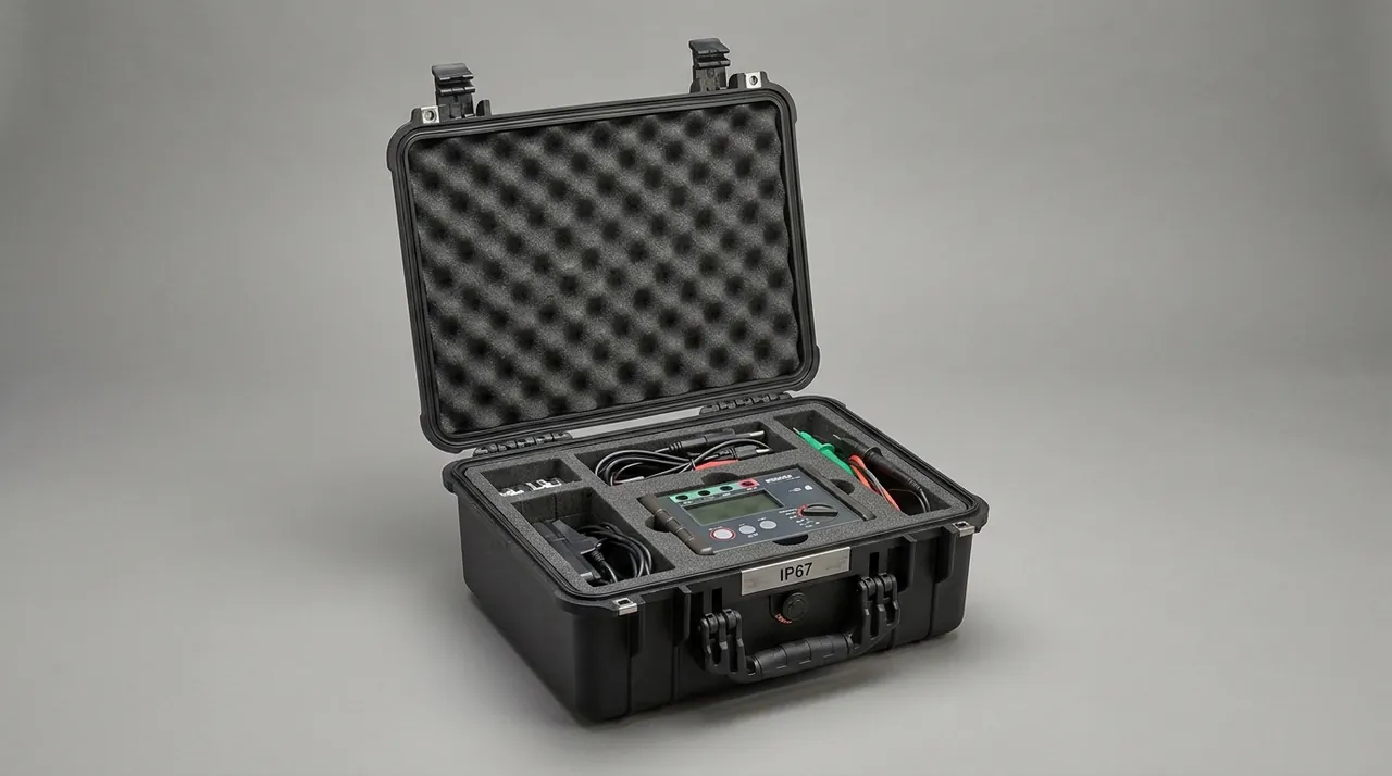
Drive and power units shift the emphasis to mechanical fastening. Bus capacitors, IGBT modules and heatsinks are usually screwed to a mounting plate, and sustained vibration can relax the preload. The drive nest should therefore let the housing carry the load, keep the heatsink free of stress and leave the terminal side clear, with a torque spot-check on key fasteners at every return to store.
Bagging Practice for Shielding Bags and the Opening Sequence
The shielding bag is the first barrier for a board, but it is often mistaken for a complete solution. Its job is to shield electric fields and drain static slowly, not to provide mechanical cushioning, and it cannot stop water vapour permeating over months. A shielding bag must therefore be used together with case cushioning and desiccant.
Two bag types are common. Metallised shielding bags, with surface resistance typically between 1 x 10^4 and 1 x 10^6 ohm, offer good field shielding for general boards. Moisture-barrier bags, usually a laminate of metallised polyester and polyethylene, have very low water-vapour transmission and suit long-term storage and sea freight, but they require desiccant and an internal humidity indicator card.
Bagging rules worth writing into the procedure: enclose the board completely and keep the bag slack modest so the board cannot slide inside; add desiccant sized to the bag volume, roughly 20 to 30 g of silica gel per 10 litres; never substitute a plain PE zip bag, because plain PE can accumulate several kilovolts; apply the external label before sealing, with board name, hardware revision, serial number and packing date; and orient the board so its long edge runs along the short edge of the case.
The opening sequence needs the same discipline, because that moment carries the highest electrostatic risk. The operator drains the body through a wrist strap before touching the case, places the case on a flat bench and opens the latches without prying the seal with metal tools, removes the shielding bag and lets it rest briefly on a grounded surface before opening it, then lifts the board by its edges or metal frame only, never touching gold fingers or components. Boards in BGA packages that have been stored beyond the manufacturer's limit also need a bake-out before installation to avoid the popcorning effect during any reflow, a point that matters when a service partner carries out local repair.
Handling the Weight and Awkward Shape of Drives and Inverters
The drive unit is the hardest component in a controller to move, because its weight spans a wide range, its shape is irregular and it usually carries protruding heatsinks, busbars and terminals.
By weight, common classes are small integrated units at 3 to 10 kg, carried by one person using side handles and liner location; medium wall-mounted units at 15 to 40 kg, which need two-person lifts and a pull-out tray; cabinet-mounted units at 25 to 60 kg, which suit base wheels and a telescopic handle; and large cabinet units at 60 to 200 kg, which require an aluminium frame with marked lifting points.
Awkward geometry creates three specific risks. Heatsink fins are sharp and can cut harness, gaskets and hands, so the heatsink side needs its own chamber with a soft edge guard and must never share a compartment with boards. Offset centre of gravity means weight usually concentrates on the heatsink side, so a single-point lift tilts the case; lifting points belong on both sides of the centre-of-gravity projection. Missing handles on many factory units force a body hold, which is exactly why a pull-out tray is worth specifying, allowing the drive to slide out as a unit instead of being hugged out of a deep cavity.
Tilt limits also matter. Bus capacitors and power modules are designed for vertical loading, and carrying a unit tilted beyond about 30 degrees for any length of time applies non-design loads to fasteners and solder joints. For large units, mark the tilt limit and the lifting points on the case itself. Wheel and handle details for heavy cases are covered in Case Wheels and Trolley Handle.
Machine-Room and Hoistway Logistics: Access, Lifting and Wheels
Logistics in this industry rank among the harshest of any industrial setting. Machine-room corridors are often only 700 to 900 mm wide and usually include thresholds, steps and corners, while hoistway transfers are tighter still, sometimes requiring the car top or the pit, with restricted space and limited sight lines.
For machine-room access, keep case width below 600 mm so that a 700 mm corridor still allows the operator to turn, and keep height under about 900 mm so the centre of gravity stays low on stairwells. Wheel choice directly determines on-site efficiency. Wheels of 100 to 125 mm handle thresholds and sills better, and each wheel should be rated for at least 60 kg. Polyurethane wheels suit epoxy floors because they cut noise and marking, while rubber wheels grip better outdoors and on rough ground. A wheeled case should have a folding or detachable handle so the handle does not become an obstacle in a narrow corridor.
Hoistway transfers add two requirements. Single-case weight must match the load capacity of the car top or pit route, with no multi-point stacking, and the case must tolerate the standing water that can collect in a pit, which makes a rating of IP65 or better and a removable desiccant cartridge necessary. Fall protection is equally important: the case must be secured to a lifting line or safety rope inside the hoistway, and carrying it by hand alone must be prohibited.
For frequent maintenance rounds, a two-case strategy works well: a depot keeps a large primary case with the full spare set, while the service vehicle carries a small fast-access case holding only the boards and terminals likely to be needed that day, which reduces heavy trips and liner contamination. Cost drivers across these options are broken down in Case Cost Structure.
Reusing the Case as an On-Site Container Against Machine-Room Dust
Machine-room dust differs from ordinary workshop dust. Brake wear produces graphite powder, door-operator belts shed rubber particles, and the hoistway contributes cement dust and metal swarf; over time these combine with oil mist into an adherent film. The particles are fine and sticky, and once they reach a board slot or a connector pin field they can reduce insulation resistance, degrade contact quality and, in a humid season, trigger surface tracking.
A protection case should therefore be designed explicitly to be reused as on-site temporary storage rather than treated as one-trip packaging. That positioning produces three concrete requirements.
First, the sealing target is dust rather than immersion. Machine rooms rarely flood, but dust and moisture are constant. IP65 blocks dust jets and brief spray while avoiding the weight and opening effort of IP67; where a case may sit in a pit, move up to IP67 with a pressure-equalisation valve. Second, the case must manage humidity while closed for long periods. Provide a replaceable desiccant cartridge and a humidity indicator card that triggers replacement above 40 percent relative humidity; close the valve for storage and allow it to breathe in transit so pressure differentials cannot damage the gasket, as described in Pressure Equalisation Valve. Third, the closure hardware must be rated for high cycle counts. On-site work can open a case many times in a day, so latches and hinges should target at least 50,000 cycles, with an assistance mechanism and a clear unlatched indicator to prevent a case springing open in transit.
Treating the case as a standard on-site container has a management benefit as well: fixed layout and fixed item positions mean technicians never reorganise the contents, every item has a home, and a missing part is visible at a glance, which is especially valuable for teams covering several districts. Temperature behaviour of liners across seasons is covered in High and Low Temperature Testing.
Choosing an IP Rating: Storage Condition versus Installed Condition
Ingress protection is one of the most misunderstood parameters in elevator control equipment, because the requirement for an installed cabinet and the requirement for a transit case have entirely different origins.
An installed cabinet takes its rating from its location. Cabinets in an electrical machine room normally need IP20 or better; in damp machine rooms with spray risk the cabinet may reach IP54 to IP55; components installed in the hoistway are usually treated as IP54 because of dust. These ratings describe long-term service protection at the installed location and are not a substitute for anything else.
A transit case takes its rating from the worst condition on the route: brief rain, site hose-down, pit water, or storage on an open goods yard. The selection logic is therefore as follows.
Indoors and in a finished-goods store, IP54 suffices because dust is the main concern and a washable liner is an advantage; urban project delivery calls for IP65 against brief rain and wind-blown dust; cross-region road transport calls for IP67 against temporary immersion and road spray together with a pressure-equalisation valve; and pit or damp machine-room storage calls for IP67 plus desiccant and a humidity indicator card.
One boundary must be stated clearly: the transit case rating never replaces the cabinet rating. A transit case finishes its job the moment the equipment is installed, whereas the cabinet must resist the machine-room environment for its entire service life. Confusing the two can lead a site team to assume that because a case exists, the cabinet needs no sealing measures of its own. Differences between common grades and their test methods are compared in IP65 vs IP67.
Shell Options Compared: Rotomoulded PE, Injection PP and Aluminium Frame
The shell determines cost structure, weight and reuse cycles, making it the most consequential selection in a controller-component logistics project.
| Option | Typical wall | Tooling cost | Unit cost | Weight | Reuse cycles | Best suited to |
|---|---|---|---|---|---|---|
| --- | --- | --- | --- | --- | --- | --- |
| Rotomoulded PE | 3 to 6 mm | Low to medium | Medium | Heavy | 1000 and above | Large, heavy, irregular payloads |
| Injection PP | 2.5 to 4 mm | High | Lowest at volume | Medium | 2000 and above | Small to medium board cases at volume |
| Aluminium frame plus panels | 1.5 to 3 mm profile | Lowest | Highest | Lightest | 3000 and above | Precision boards needing shielding and rigidity |
Rotomoulded PE offers relatively low tooling cost, the ability to form large and complex shapes, uniform wall thickness, and good impact and weather resistance, which suits drives and complete cabinet modules. The penalty is weight: at equal volume it is typically 20 to 40 percent heavier than an injection-moulded equivalent, a difference felt immediately on a stairwell. Injection PP suits small and medium board cases with stable volume. Moulding gives tight dimensional accuracy, good surface quality and free rib design, so adequate stiffness can be achieved at thinner walls and lower unit weight, but tooling cost is high and requires sufficient annual volume to amortise, which favours established models and long-term supply. Aluminium frame with panels is common in this industry for precision boards and electromagnetic shielding. The extrusion provides rigidity and dimensional stability, and conductive anodising or coatings deliver shielding and static drainage at the lowest weight, but unit cost is highest and dissimilar-metal contact points need stainless fasteners with isolation to avoid galvanic corrosion. Moulding routes are compared further in Rotomolded Cases and Injection Molded Cases.
Select in three steps: payload, route and annual volume. Heavy irregular parts on harsh routes at medium volume point to rotomoulded PE; standard boards at high volume on stable models point to injection PP; precision boards requiring shielding and low weight point to an aluminium frame.
Compartments, Foam Layers and Positive Location
The liner actually interacts with the payload. Controller-component liners must balance compartmentation against foam conformity: too many compartments thin the cushion, while too few let boards press against one another.
A three-layer composite works well: outer EPE for support and energy absorption, middle EVA carved for location, inner IXPE or low-density PU for soft contact. Outer EPE at 25 to 35 kg/m³ gives 30 to 50 mm of large-area absorption covering base and walls; middle EVA at 40 to 80 kg/m³ is carved into recesses with 1 to 2 mm clearance per side for stable location; inner IXPE at 30 to 60 kg/m³ adds a 3 to 5 mm surface-protection and friction-control layer; and low-density PU at 20 to 45 kg/m³ provides a soft compression layer of 2 to 5 mm.
Three rules of thumb apply to board location: keep board pitch at least 15 mm for component height and finger access, keep board edge to case wall at least 10 mm, and leave 5 mm of settlement clearance at the base of a vertical slot so gold fingers never bear on a hard slot floor. Boards longer than 300 mm need a mid-span location block to prevent bending vibration in transit.
Heavy items such as drives call for a pull-out tray structure: the unit sits on an independent tray with lifting points on both sides, so it can be slid out and positioned directly without being carried through a confined space, and the tray needs a positive lock to stop it moving fore and aft in transit. Foam types and combinations are described in Case Internal Foam Types.
Labelling, Revision-Level Traceability and Travelling Documents
Revision management for elevator control boards is more complex than in most industries, because one board model may exist in several hardware revisions and several software revisions, and different project batches may require combinations that are not interchangeable. A single revision mix-up can present as a communication failure, unrecognised parameters or a drive that simply will not run, and troubleshooting is costly.
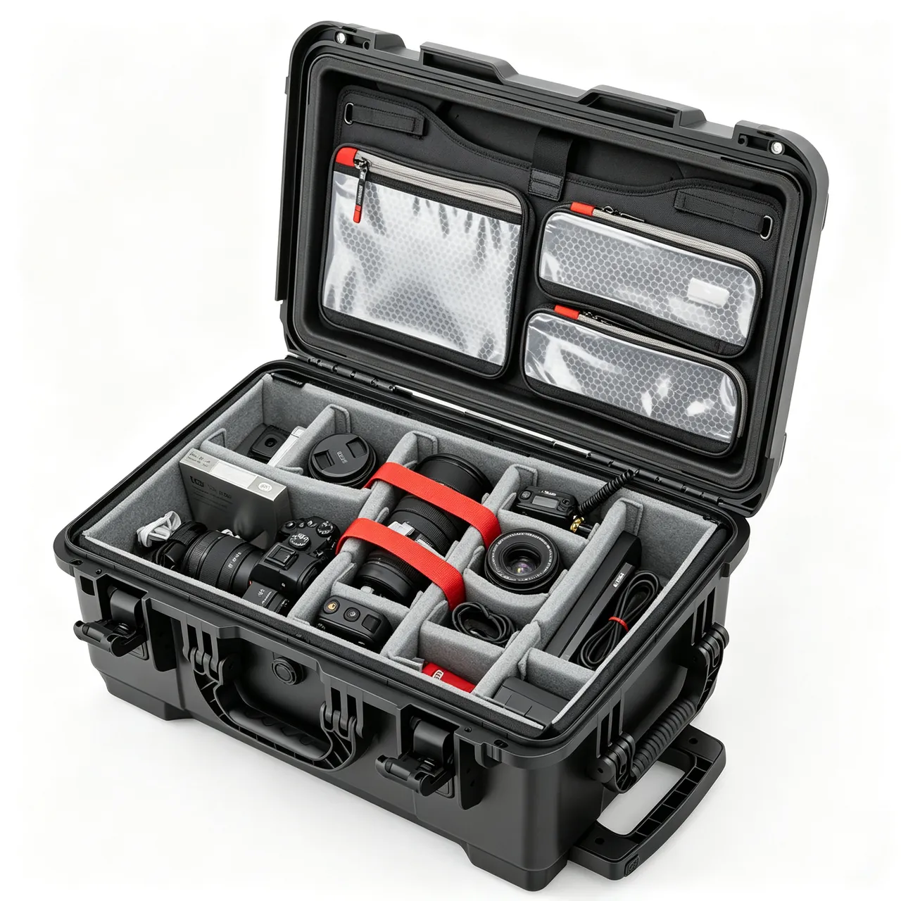
Identification must therefore reach revision level, not merely state what is inside the case. Three layers work well. The exterior label carries project number, lift range, packing date, contents summary, responsible person and contact number, printed on weather-resistant polyester with a matt laminate so barcodes stay readable. Compartment labels use letter and number combinations such as A1 to A6 for main board, I/O board, drive and terminals, mapped one-to-one to liner recesses. Item-level labels give board name, hardware revision, software revision and serial number, with drives also showing rated power, serial number and date of manufacture.
QR-code asset tracking is particularly valuable in maintenance work. Assign a code to every board and every drive so that scanning brings up hardware and software revision, compatible lift models, test records, the last project served and current status. This follows the management approach in Labelling and Asset Tracking and sharply reduces the chance of installing a wrong revision.
Travelling documents should be a fixed, itemised set: a packing list with serial numbers and revisions for verification at every opening, a revision cross-reference table confirming board-to-lift compatibility, site wiring diagrams and terminal definitions, an opening checklist recording appearance and shielding-bag condition, a desiccant and humidity log kept every three to six months, and a QR asset inventory updated on change. The document pocket is itself a constraint: abnormalities are recorded only when the operator must confirm that nothing was wrong and that revisions matched.
Acceptance Criteria and Re-Verification Intervals
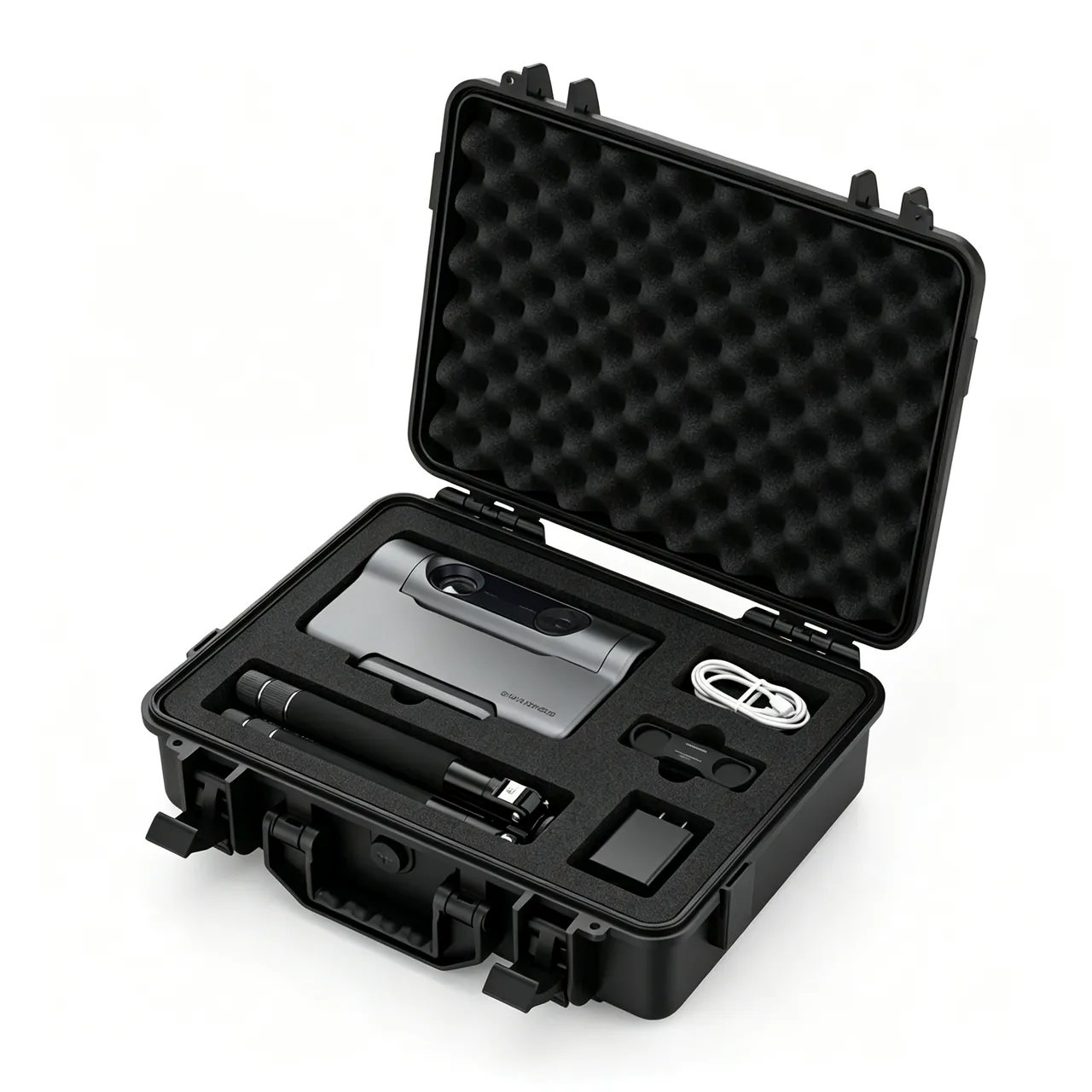
Once a case enters a maintenance system its performance must stay verifiable, so the purchase specification should define the following criteria.
| Item | Criterion | Test method |
|---|---|---|
| --- | --- | --- |
| Appearance and dimensions | No deformation or burr, cavity within 2 mm | Visual and calliper |
| Sealing performance | IP65 or IP67, no ingress | IEC 60529 or GB/T 4208 |
| Pressure-equalisation valve | Cracking at 15 to 50 mbar, no reverse leakage | Pressure bench and immersion |
| Liner surface resistance | 1 x 10^4 to 1 x 10^9 ohm | High-resistance meter |
| Ground continuity | Terminal to furthest liner point at most 1 x 10^9 ohm | High-resistance meter |
| Liner fit | Lateral clearance at most 2 mm, compression 2 to 5 mm | Feeler gauge and visual |
| Drop test | Per GB/T 4857.5 or ISTA 3A, in-case recorder within target | Whole-case drop with recorder |
| Stacking load | 1.5 times stacking load for 24 hours, deformation at most 2 mm | Static load test |
| Salt spray | No substrate perforation after 480 hours neutral salt spray | GB/T 10125 |
| Label durability | Legible after 50 alcohol wipes | Wipe test |
Recommended intervals are quarterly for liner surface resistance, ground continuity, latch and hinge action and gasket appearance; half-yearly for seal re-testing, desiccant and indicator replacement and liner indentation checks; and annually for sampling drop and stacking tests, valve function and label durability. After any drop, immersion, over-temperature event or obvious impact, run the three checks of seal, grounding and liner immediately and record them in the case history.
Disposition rules should be equally explicit. Replace rather than patch a gasket with permanent deformation, cracking or increased hardness. Replace a liner region compressed by more than 20 percent of its original thickness as a module rather than re-lining the whole case. Downgrade a shell with cracks or failed latches to non-precision duties. Replace outright any valve that has admitted water or shows abnormal cracking pressure. For cases used in dusty machine rooms, watch hinge, latch and rivet wear, and use high and low temperature testing to confirm liner dimensional stability across the seasonal range.
Frequently Asked Questions FAQ
Q: Why do elevator controller boards need a protection case rather than the original carton and foam?
A: Original cartons are usually adequate for a single shipment, but they fail quickly under two conditions common in this industry. First, project sites rarely offer dry, clean, sheltered storage, so a carton absorbs moisture, collects dust and loses rigidity in a machine room, and after repeated handling it collapses and becomes a dust source itself. Second, service replacement requires the same container to survive many round trips, which a carton cannot do in terms of opening cycles and stacking. A professional case turns one-trip packaging into a reusable on-site workstation: the seal blocks machine-room dust and brief spray, the dissipative liner provides a drain path, carved EVA slots keep vertically stored boards from touching, and a fixed document pocket holds the revision cross-reference table and opening checklist. Measured over a thousand or more reuse cycles, the cost per trip is far lower than replacing cartons and damaged boards. Where the same board type is stocked for several building models, the label should also state the software variant, because a board that fits mechanically may still load the wrong control logic. Q: How should dissipative and conductive foam be chosen, and can the two be combined?
A: The two classes have different resistance ranges and different jobs. Dissipative foam, typically 1 x 10^4 to 1 x 10^9 ohm, drains charge slowly and evenly, which makes it suitable as the primary case liner beneath boards already inside a shielding bag, because no high potential builds and no secondary discharge occurs. Conductive foam, typically 1 x 10^3 to 1 x 10^5 ohm, drains faster and is used mainly for handling trays, bag liners and situations needing field shielding. They can be combined, but conductive foam should not sit directly against the bare solder side of a board over a large area, because the material is essentially a conductor and tight contact with exposed pads or vias can create a local shunt path. The safe sequence is shielding bag first, then conductive foam slot or dissipative liner recess. Whichever is chosen, the liner must have a continuous drain path to the shell, with terminal-to-furthest-liner resistance no greater than 1 x 10^9 ohm, checked quarterly.
Q: How should a drive unit be secured inside the case, and what tilt and load limits apply?
A: Three principles govern drive protection: the housing carries the weight, the heatsink carries no load, and the terminal side stays clear. The unit should rest on its base or mounting flange on a tray so that the housing takes all the weight, never the heatsink or the terminals. The heatsink side needs its own chamber with a soft edge guard and must not share space with boards, because the fins are sharp enough to cut harness and gaskets. For handling, specify a pull-out tray so the unit slides out as a whole rather than being hugged out of a deep cavity, and place lifting points on both sides of the centre-of-gravity projection so a single lift cannot tilt the case. Keep tilt within about 30 degrees, because bus capacitors and power modules are designed for vertical loading and prolonged large-angle carrying applies non-design loads to fasteners and solder joints. Units above 60 kg need marked lifting points, a stated tilt limit and on-site handling guidance in the documents.
Q: Can a shielding bag carry the whole protection task, and what does the opening procedure require?
A: No. A shielding bag shields electric fields and drains static slowly; it provides no mechanical cushioning and cannot stop water vapour permeating over months. For cross-region transport or long storage, use a metallised shielding bag or a moisture-barrier bag with desiccant sized at roughly 20 to 30 g of silica gel per 10 litres, plus a humidity indicator card. Never substitute a plain PE zip bag, because plain PE can accumulate several kilovolts in dry conditions. The opening procedure matters just as much, since that is the highest-risk moment. The operator drains the body through a wrist strap before touching the case, opens the latches on a flat bench without prying the seal with metal tools, removes the bag and lets it rest briefly on a grounded surface before opening it, and lifts the board only by its edges or metal frame, never touching gold fingers or components. Boards stored beyond the manufacturer's limit also need a bake-out before installation.
Q: What is the relationship between the case IP rating and the cabinet IP rating?
A: They are independent and neither substitutes for the other. A protection case rating describes how well boards and drives are protected during transport and on-site temporary storage, and it follows the worst condition on the route, such as brief rain, site hose-down, pit water or storage on an open goods yard, which is why cross-region transport usually calls for IP67 with a pressure-equalisation valve. A cabinet rating describes long-term protection at the installed location and follows the installation position: cabinets in an electrical machine room normally need IP20 or better, damp machine rooms with spray risk may reach IP54 to IP55, and hoistway components are usually treated as IP54 because of dust. One misunderstanding must be avoided, namely the idea that a case removes the need for cabinet sealing, because the transit case finishes its work once the equipment is installed while the cabinet must resist dust, moisture and temperature for its whole service life. Define both ratings on separate lines with separate acceptance criteria.
Q: How should case dimensions and wheels be chosen for machine-room and hoistway conditions?
A: Work backwards from the access dimensions on site. Machine-room corridors are often 700 to 900 mm wide, so keep overall case width below 600 mm to preserve turning room, and keep height under about 900 mm so the centre of gravity stays manageable on stairwells. For wheels, diameters of 100 to 125 mm handle thresholds, sills and cable ducts better, and each wheel should be rated for at least 60 kg. Polyurethane wheels suit epoxy floors because they reduce noise and marking, while rubber wheels grip better outdoors and on rough ground. A wheeled case should have a folding or detachable handle so it does not become an obstacle in a narrow corridor. Hoistway transfers require two further disciplines: single-case weight must match the capacity of the car top or pit route with no multi-point stacking, and the case must be secured to a lifting line or safety rope inside the hoistway, since carrying it by hand alone risks both injury and equipment damage.
Q: How should rotomoulded PE, injection PP and an aluminium frame be compared for selection?
A: Decide in three steps: payload, route and annual volume. For heavy irregular payloads such as drives and complete cubicle modules on harsh routes at medium volume, rotomoulded PE is usually first choice, because tooling cost is relatively low, large complex shapes are feasible, wall thickness is uniform, and impact and weather resistance are good, at the cost of being 20 to 40 percent heavier than an injection-moulded equivalent at equal volume. For standard boards on stable models at high volume, injection PP wins, since moulding delivers tight dimensional accuracy, free rib design and adequate stiffness at thinner walls, lowering unit weight, but tooling cost is high and needs sufficient volume to amortise. For precision boards that need electromagnetic shielding and low weight, an aluminium frame with panels is the right answer: extrusion gives rigidity and dimensional stability and conductive anodising provides shielding and static drainage at the lowest weight, while unit cost is highest and dissimilar-metal contact points need stainless fasteners with isolation.
Q: When a case is reused on site as a storage container, how should dust and moisture be managed?
A: Sealing, drying and cycling must work together. For sealing, the machine-room threats are brake graphite powder, door-operator rubber particles, cement dust and oil mist, and IP65 is enough to block dust jets and brief spray without paying the weight and opening effort of IP67; if the case may sit in a pit, move up to IP67 with a pressure-equalisation valve. For drying, provide a replaceable desiccant cartridge and a humidity indicator card that triggers replacement above 40 percent relative humidity; close the valve for long storage and allow it to breathe in transit so pressure differentials cannot push the gasket out of its groove. For cycling, on-site work often opens a case many times a day, so target at least 50,000 cycles for latches and hinges and choose a design with a clear unlatched indicator so the case cannot spring open during handling.
Conclusion and Related Reading
Controller-component cases are calibration and revision control hardware. JUNZHIJIA supplies carved EVA slots, EPE support, dissipative materials, pull-out trays and tooling through OEM and ODM programmes. Manufacturing is by Kexin New Materials (Guangdong) Co., Ltd.
Related Reading