

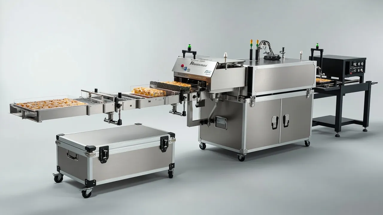
The two core actions of a food packaging machine — forming and sealing — rest on one shared precondition: the geometric precision and surface integrity of the components must not have changed by the time they are installed. Once a forming cavity has been dented, wall thickness distribution across the formed pack becomes uneven. Once a heat sealing jaw face has been compressed or locally scratched, the seal is either weak or over-sealed. What these two failures share is that they are invisible at receiving and only appear once production starts, and by then the cost is machine downtime plus scrapped product. The packaging design objective for forming and sealing components is therefore specific: protect the working surface, resist stacking and impact loads, exclude dust and grease, and deliver parts that can go straight to assembly with no rework. That objective is achieved mainly through structure, not through thicker cushioning material.
This article is written for food packaging machinery manufacturers, packaging line equipment engineers and spare parts buyers. It covers protection priorities for forming and sealing components, liner layout options, food contact and cleanliness compliance, delivery configurations and acceptance flow. Standards are cited with their applicable scope so they can be quoted in a technical annex. The guidance below reflects JUNZHJIA's accumulated practice on food-packaging case projects.
Contents
- 1. The shared weak points of forming and sealing components
- 2. Forming moulds and rollers: cavity faces and surface coatings
- 3. Heat sealing jaws and sealing clamps: thermal uniformity depends on surface integrity
- 4. Cutting, perforating and consumable blade components
- 5. Vacuum and pneumatic components: pump bodies, valve islands and seals
- 6. Drive and guide components: chains, rails and timing parts
- 7. Food contact compliance and lubricant segregation
- 8. Cleanliness control: deriving packaging requirements from the hall environment
- 9. Liner layouts: heavy, long and irregular components
- 10. Case sealing, stacking and handling
- 11. Delivery configurations and acceptance release
- 12. Customization, records and maintenance coordination
- Frequently asked questions
- Conclusion and related reading
1. The shared weak points of forming and sealing components
Grouping forming and sealing components together makes sense because they share three weak points.
The first is surface precision. A forming cavity face, a heat sealing jaw working face and a roller outer diameter all work with their surfaces. Losing surface precision does not require a heavy impact; a single point contact with a hard component or one unreasonable stacking load can leave an unrecoverable mark. Worse, such marks are amplified in service: a dent in a forming face is reproduced cyclically on every pack, and a scratch on a sealing face lowers the sealing pressure at that location and produces a cyclic weak seal.
The second is thermal uniformity. Heat sealing jaws and some forming moulds contain heating elements and temperature sensors, and seal quality depends on even working-face temperature. If the part bends in transit, the relative position of the working face and the heating element changes, the temperature distribution shifts, and the result is a locally weak seal. This failure is even more concealed because the component may look entirely normal.
The third is surface condition. Platings, coatings and polished faces can oxidize, discolour or micro-scratch through friction and moisture in transit; contact with grease or sulphur-bearing rubber can produce stains that are very hard to remove and that directly affect heat transfer during sealing.
Together these three points lead to one conclusion: the packaging principle for forming and sealing components is that the working surface touches nothing and carries nothing. This differs from the conventional heavy-component approach of distributing load across multiple support points, and it requires a dedicated design.
2. Forming moulds and rollers: cavity faces and surface coatings
Forming moulds are typically block, plate or roller shaped, vary widely in weight, and demand high cavity face precision.
| Component | Form and critical face | Main risk | Protection focus | Packing action |
|---|---|---|---|---|
| --- | --- | --- | --- | --- |
| Block forming mould | Cavity face, parting face | Dented cavity, damaged parting face | Working face clear | Support on base, cavity facing up and untouched |
| Forming or pressure roller | Outer diameter, coating | Scratched diameter, bent body | Full perimeter protection | V-cradle, journal support at both ends |
| Mould inserts and cores | Small precision fits | Deformation, mix-ups | One part per cavity | Numbered cavities, mating faces apart |
| Cooling and heating blocks | Water passages, sealing faces | Damaged ports, internal corrosion | Port capping | Cap ports, dry interior before sealing |
| Parting face strips and guide posts | Fit precision | Bending, corrosion | Rigid support | Stand upright, add corrosion protection |
| Vacuum plate | Flatness and air holes | Deformed face, plugged holes | Full face support | Flat with full-face support, cap the holes |
The rule for forming moulds is that the working face points up or outward and stays clear. If a mould is placed cavity-face down on a base plate, even with elastic material underneath, the mould's own weight concentrates stress on the cavity edges, and transport vibration readily produces burrs or rounded corners. The correct arrangement is to load through the parting face or the base, keep the cavity face clear, and add a removable protective cover inside the case so nothing can touch the cavity before unpacking.
Roller-type components should be supported at both journals in a V-cradle so the roller body carries no load. This protects the outer diameter coating and prevents bending. Coated surfaces should also be kept away from sulphur-bearing rubber, felt and newsprint, all of which can discolour platings under damp conditions.
For large forming moulds that must be lifted as a whole, the case should have design lifting points and a marked centre of gravity. The general practice described in transport protection for moulds and mould-type components applies here, particularly regarding working face protection and the load path arrangement.

3. Heat sealing jaws and sealing clamps: thermal uniformity depends on surface integrity
Heat sealing jaws and sealing clamps are long precision components, sometimes over a metre, and most carry heating and temperature sensing features.
The core risk for a heat sealing jaw is bending. A long thin-walled structure is most vulnerable to two loads in transit: bending oscillation from end supports with a free mid-span, and stacking pressure applied directly to the jaw body. Once bending occurs, the fit between jaw face and anvil changes, sealing pressure distribution is no longer even, and the result is a cyclic weak seal. The jaw should therefore be carried on a multi-point full-length cradle: three or more supports along the full length, with flexible contact material that touches only the jaw back or mounting face and never the working surface.
Coatings and PTFE-type surfaces are the other concern. These surfaces provide release properties, and once scratched or dented they lose that function, so film sticks to the jaw and the line stops frequently for cleaning. Leave a clear cavity for the working face, let nothing touch it, and avoid applying protective film to it, since adhesive residue is a risk in this context too.
Sealing clamps and clamping mechanisms consist of linkages, springs and jaw teeth. The tooth profile is functionally critical and the tips crush easily, so jaws must never be pressed against each other or pinned under a load. Springs should not be stored under sustained compression; if the case is laid on its side in transit, a spring can deform slightly under its own weight, which is why the upright orientation must be marked on the exterior. Sealing clamps are often integrated with pneumatic or servo drives, and the relevant protection points for cylinders, fittings and oil ports are set out in transport protection for hydraulic and lifting components.

4. Cutting, perforating and consumable blade components
Cutting and perforating components on a food packaging machine are small, numerous and frequently replaced, which makes them ideal candidates for a modular liner with spare positions.
| Component | Critical feature | Main risk | Liner design suggestion |
|---|---|---|---|
| --- | --- | --- | --- |
| Cross and longitudinal cutters | Edge straightness, hardness | Chipped or rolled edge | Edge up or sideways and clear, individual elastic grip |
| Perforating needles and punches | Needle tip, punch end face | Broken needle, damaged end face | One hole per part, hole deeper than the part |
| Serrated and profile blades | Complex edge form | Chipped teeth | Custom profile cavity, no contact on any side |
| Blade holders and carriers | Mounting face and locating holes | Scored locating face | Mounting face up, supported from below |
| Spare blade sets | Many small parts | Mix-ups, scattered parts | Numbered cavities, spare positions, count marking |
| Blade fasteners | Small, easily lost | Loss, mix-ups | Same cavity as the matching blade, never mixed by size |
These components share one requirement: the cutting edge must never touch any material. Keeping the edge clear is the baseline rule, yet in practice it is often violated because space is tight and the edge ends up resting against the liner. This looks harmless in the short term but produces micro-chipping under transport vibration. The design solution is to grip the blade back and leave the edge in free space, and to choose liner material far softer than the blade so that even accidental contact does not damage it.
For blade-type spares, provide spare positions with count marking so an operator can see at a glance how many remain. This small detail is very effective at preventing a second shutdown caused by discovering too few blades at installation time. The same idea of multi-cavity location for small parts with count management is covered in removable divider systems in component cases.
5. Vacuum and pneumatic components: pump bodies, valve islands and seals
Vacuum and pneumatic spares fail differently from mechanical parts; the dominant issues are sealing and contamination.
- Vacuum pumps and vacuum generators. Internal clearances are fine, so dust or moisture drawn in during transit reduces pumping efficiency after installation. Cap the inlet before shipping and seal the interior after drying. If the pump contains oil, maintain the specified oil level and orientation per the maker's instruction and mark the upright direction on the case.
- Valve islands and solenoid valve groups. These have dense mating faces and seals, and any particle ingress causes internal leakage or erratic actuation. Locate the assembly as a single unit, cap every port, and ensure mating faces carry no load.
- Pneumatic actuators (cylinders, rotary actuators). The piston rod is a precision surface and must avoid side load; a free rod span must never be used as a support point.
- Seals and hoses. Elastomers suffer compression set and ageing, so store flat, away from light and grease. Hoses should not be coiled at a small radius, which leaves permanent kinks.
- Vacuum cups and filter elements. Cup lips deform easily and need a dedicated cavity free of compression; filter elements should stay dry to avoid mould growth.
Vacuum and pneumatic components are generally more moisture sensitive than mechanical parts, so long-haul or cross-climate shipments benefit from desiccant and a humidity indicator card. Where temperature control also matters, apply the approach in cold chain and temperature controlled packaging design.
6. Drive and guide components: chains, rails and timing parts
The forming and sealing actions are driven through the transmission system, and drive spares are typically long, making them vulnerable to bending and contamination in transit.
| Component | Critical point | Transit risk | Suggested measure |
|---|---|---|---|
| --- | --- | --- | --- |
| Chains and chain plates | Pitch and articulation freedom | Bending, corrosion, seizure | Coil at large radius, oil and seal |
| Guide rails and slide rails | Straightness and raceway | Deformation, dented raceway | Full-length rigid support, raceway clear |
| Timing belts and pulleys | Tooth form and groove | Kinks, damaged tooth faces | Coil at large diameter, teeth not in contact |
| Couplings and drive shafts | Mating faces and keyways | Scratches, bending | Stand upright, protect mating faces |
| Linear bearings and carriages | Raceway precision | Dented raceway, dust ingress | Individual cavity with end caps |
| Cams and index mechanisms | Profile precision | Damaged profile | Profile face up and clear |
Rails and slide rails are classic "long parts that hate bending," and full-length cradling is better than tying them at a few points. Timing belts suffer from permanent tooth deformation caused by small-radius bending, so the coil diameter should generally exceed the maker's minimum. Where a drive component is also a precision transmission item, apply the locating and cushioning practice in anti-vibration protection for precision transmission components.
7. Food contact compliance and lubricant segregation
On a food packaging machine, the parts that contact packaging material or food — forming faces, sealing faces, film guides, vacuum cups — should be controlled in the food contact material framework. The GB 4806 series is the Chinese national standard system for food contact materials and articles, setting requirements for raw materials, sensory properties, migration and overall migration for plastics, rubbers and coatings among others. In the packaging context, two things must be done.
First, packaging materials touching food contact surfaces must be controlled. Liners, protective films and bag material that sit against a working face for extended periods should have their grades stated, with excluding regrind and unsuitable additives from the polymer, and releasing material declarations and test reports to the agreed scope.
Second, lubricants must be strictly segregated. This is where accidents most often happen: spares, grease and chain oil travelling in the same vehicle or case, the oil leaks, the liner adsorbs it, and it then transfers to a forming or sealing face. Grease residue on a forming face causes poor release, and on a sealing face it causes abnormal seal strength; both are harder to remove than dust.
| Item | Conflict with spares | Consequence | Handling rule |
|---|---|---|---|
| --- | --- | --- | --- |
| Chain and gear oil | Leaks, then liner adsorbs it | Poor forming, abnormal seal strength | Independently sealed, never co-packed |
| High temperature grease | Flows when warm | Contaminates sealing face and heating zone | Separate case, away from hot components |
| Food grade grease | Still a grease | Contaminates working face, adsorbs dust | Same batch allowed, different case |
| Cleaners and adhesive removers | Volatile and corrosive | Coating discolouration, rubber ageing | Never stored or shipped together |
| Rust preventive oil (drive parts) | Volatiles are adsorbed | Affects contact surface cleanliness | Drive parts only, separately sealed |
8. Cleanliness control: deriving packaging requirements from the hall environment
Cleanliness requirements in food packaging halls vary with the product. Dry goods packaging typically needs dust and pest exclusion, while dairy and wet food packaging adds humidity and microbiological concerns. The packaging class should not be applied uniformly; derive it from the hall environment. The clean zone classification methods in the ISO 14644 family and the contamination control principles of GMP both serve as a basis.
| Hall type | Primary control objective | Packaging requirement | Unpacking requirement |
|---|---|---|---|
| --- | --- | --- | --- |
| General dry goods hall | Dust and pest exclusion | Low-shedding liner, pest-tight case | Remove exterior dust before entry |
| High cleanliness hall | Particle control | Clean grade, non-shedding liner | Strip outer case in airlock, inner case enters |
| Wet food hall | Humidity and microbes | Non-absorbent, mould-resistant liner with desiccant | Install promptly, avoid prolonged exposure |
| Area linked to an aseptic line | Per process validation | Sterilizable liner entering with the part | Follow aseptic area transfer procedure |
One point deserves emphasis: cleanliness control works through procedure and materials, not through adding packaging layers. Multiple wrapping layers have two counterproductive effects: they generate more particles at unpacking, and they increase the risk of fibre shedding from the material itself.
9. Liner layouts: heavy, long and irregular components
Forming and sealing components vary greatly in form, so liner layout should be designed by type.
| Layout option | Suitable components | Structural points | Advantages | Risk note |
|---|---|---|---|---|
| --- | --- | --- | --- | --- |
| Compartment location | Blades, inserts, seals, valves | One part per cavity, walls between | Prevents mix-ups and mutual impact | Over-tight cavities lead to prying damage |
| Full-length cradle | Heat sealing jaws, rails, drive shafts | Three or more supports, working face clear | Strong bending resistance | Support positions must follow stiffness distribution |
| Rigid tray with elastic isolation | Forming moulds, rollers, pump bodies, valve islands | Rigid base carries load, thin elastic layer isolates | Clear load path, stack resistant | Excessively thick elastic layer introduces freedom |
The three options can be combined: a rigid tray carries the load, compartments locate the small parts, and long components occupy their own layer on a full-length cradle. The case should also provide a document pocket and count card position for the packing list, inspection report and consumable count record.
For cushioning material selection, compare density, rebound and compression set data in cushioning liner material comparison to trade impact resistance against stacking resistance. Multi-cavity tolerance control is covered in custom foam insert selection and design guide.
10. Case sealing, stacking and handling
Sealing grade follows the application: IP54 or better for in-plant turnover, IP65 or better for distribution and export, and IP67 where heavy washdown or short-term immersion is expected. The definitions come from IEC 60529 and GB/T 4208. For air freight or cross-climate transport, fit a pressure equalization valve so differential pressure does not load the gasket continuously; see protective case pressure equalization valve for function and mounting.
Stacking affects forming and sealing parts more directly than general components, because working faces usually sit in the middle or upper part of the case. The design principle is for stacking load to pass through the four corners and side wall columns, never through the liner or the component. If the technical annex specifies stacking layers and duration, it should also specify the validation method.
On handling, when a fully loaded case exceeds the safe two-person limit, fit castors or design a palletized case set, and provide braking on wheeled cases. Drops during handling are the most common source of damage, so corners need reinforcement and latches must stay closed under impact. Where lifting is required, mark the lifting points and centre of gravity and follow general heavy-lift safety requirements.
11. Delivery configurations and acceptance release
| Code | Scenario | Case and liner | Sealing and pressure | Acceptance focus |
|---|---|---|---|---|
| --- | --- | --- | --- | --- |
| F-1 In-plant turnover | Part replacement, commissioning, temporary storage | Portable hard case with compartment tray | IP54 or better | Handling convenience, count marking |
| F-2 Distribution transfer | Group transfer, third-party logistics | Medium case with mixed layout liner | IP65 with equalization valve | Locating reliability, complete documents |
| F-3 Export project | OEM export with machinery, overseas project | Palletized case set, item-by-item numbering | IP67 with equalization valve | Distribution cycle validation, humidity record |
A fixed five-step acceptance flow works well: exterior and seal condition assessment, liner cleanliness and integrity check, component working face inspection (full inspection for grade A), document and number verification, then release or isolation. The working face inspection should use strong oblique lighting, because scratches are hard to see under direct light.
Validate transport in layers: liner location (vibration plus drop), case sealing (dust plus water jet), and complete-case distribution cycle (combined items per the GB/T 4857 series, ISTA or ASTM D4169). Where MIL-STD-810H environmental methods are cited, note that the standard serves only as a source of methods and that testing by its methods does not indicate military certification.
Acceptance rules and sampling methods should be unified; custom case acceptance sampling provides a basis for a single acceptance sheet so sites do not diverge.
12. Customization, records and maintenance coordination
Because component turnover on a food packaging machine is high, the case system is better built as a structured family than as one-off custom pieces.
- Build a standard liner library by component family. Forming, sealing, blade and drive families each get standard liner modules, so a new part first matches an existing module, reducing tooling cost and lead time.
- Link records to case numbers. Record the case number, liner model, applicable machine and component list so inter-site transfers and stocktaking are straightforward.
- Coordinate with the maintenance plan. Bind consumable replacement intervals to spare parts case replenishment, for example "inspect the liner support face for compression whenever the heat sealing jaw is replaced."
- Inspect and replace on a cycle. Liners, gaskets and desiccant belong on a periodic inspection list. A liner showing compression, damage or discolouration should be replaced, not kept in service.
JUNZHJIA, manufactured by Kexin New Materials (Guangdong) Co., Ltd., customizes liners and sealing structures to the actual dimensions of forming moulds, heat sealing jaws, blades and drive components, supports wholesale, distribution, OEM/ODM and global supply, and can provide material statements and inspection documentation under agreement. For factory qualification, see how to choose a protective case OEM factory and move acceptance rules into the contract stage.
Frequently asked questions
Q: Why are long components such as heat sealing jaws more prone to irreversible deformation than ordinary long shafts?
A: Because a heat sealing jaw combines long, thin and working-face geometry. Its second moment of area is far smaller than a solid shaft of the same length, so its bending resistance is much lower, and its functional surface is concentrated on one side of the jaw, which means any bend immediately changes the seal pressure distribution. What makes it worse is that these parts usually carry heating and temperature sensing elements. After bending, the relative position of the element and the jaw face changes, the temperature distribution shifts, and the outcome is a locally weak seal — while a visual inspection may show nothing wrong. Two loads commonly cause the bend in transit: bending oscillation from end supports with a free mid-span, and stacking pressure applied directly to the jaw body. Protection must therefore use a multi-point full-length cradle so the jaw back or mounting face is supported at three or more points along its length with the jaw working face clear of all material. The case structure must also ensure stacking load travels through the columns rather than through the liner and jaw. Mark the upright orientation on the exterior to prevent side storage and self-weight bending, and for very long jaws consider upright or near-upright placement to reduce the unsupported span.
Q: When a forming mould is packed, is it better to have the cavity face up or down?
A: In the great majority of cases, cavity face up or outward, with the parting face or mould base carrying the load. The cavity is the functional surface and its geometric precision determines wall thickness distribution and appearance of the formed pack. If the cavity face is laid down against the base, even with elastic material beneath, the mould's own weight creates point or line contact with the liner at the cavity edges, and transport vibration readily produces burrs, rounded corners or fine dents. With the cavity up, add a removable protective cover inside the case so that nothing can touch the cavity before unpacking. The only situation that justifies a different arrangement is a mould with a very high centre of gravity where a downward-opening cavity is easier to secure; in that case use a rigid tray with local support and confirm that the cavity touches nothing. Note also that the parting faces and guide posts are precision surfaces themselves. They may carry structural load, but they must not strike each other or contact a hard component directly, so leave a small clearance and restrain with elastic material.
Q: For blade-type spares on a food packaging machine, where is liner design effort best spent?
A: On two things: keeping the cutting edge clear, and count management. Keeping the edge clear is the baseline. The edge must not touch the liner or any other component, because the cutting edge is the hardest and most brittle feature, and a tiny point contact under vibration chips or rolls it. In service a chipped edge produces an uneven cut and burrs, which then affect seal quality. Achieve clearance by gripping the blade back or body sides and leaving the edge in free space, and choose liner material far softer than the blade so that accidental contact still does no damage. Count management is often overlooked but pays off: provide spare positions with quantity markings so an operator can see at a glance how many are used and how many remain, avoiding a second shutdown when too few blades are discovered at installation. It also helps to keep same-size blades and their fasteners in one cavity to reduce searching and mismatch during assembly. Never mix different blade sizes in a shared cavity, because visually similar sizes are almost impossible to tell apart once mixed, and installing the wrong one can damage the machine.
Q: Why do drive components such as chains and timing belts get damaged in transit?
A: Because what harms them is shape memory and corrosion, not sharp impact. The typical timing belt failure is permanent tooth deformation. If the belt is bent or coiled at a small radius for packing convenience, the rubber and cord deform permanently at that radius. Once installed, pitch is no longer uniform, which shows up as transmission noise, belt tracking deviation and even tooth skipping, and the deformation cannot be removed by adjusting tension. For chains, the problems are articulation freedom and corrosion. In a damp environment the plates and pins rust, causing seizure or pitch elongation, and once the pitch grows, meshing with the sprocket degrades and wear accelerates. When packing, coil timing belts at or above the maker's minimum bend radius, or lay them flat without folding. Coat chains with rust preventive oil, coil them at a large radius and seal them individually. Support rails and slide rails over their full length to prevent bending. One further point: drive components are generally not food contact surfaces, so rust preventive oil is permissible, but they must be sealed separately from other spares so volatiles are not adsorbed by the liner and transferred to a working face.
Q: Spares and grease shipped in one case — what exactly goes wrong?
A: The problem is a chain of penetration, adsorption and transfer. Under the temperature rise of transport, grease and chain oil drop in viscosity and flow more readily, and they leak from container seams or closures. Once oil reaches the liner, the liner adsorbs it and releases it slowly over a long period. Unlike dust, this cannot simply be wiped away; the liner keeps emitting it. The oil then transfers to adjacent component surfaces, and if those surfaces are forming or sealing faces, the result is poor release or abnormal seal strength. Grease contamination is also harder to remove than dust and often requires a dedicated degreasing step, while the degreasing solvent itself may attack platings or rubber parts. The correct approach is graded segregation. Strongly contaminating or highly volatile items such as chain oil, gear oil, cleaners and adhesive removers must be independently sealed and shipped in separate cases and vehicles. Food grade grease is permitted for food contact but is still a grease, so it still contaminates working faces and adsorbs dust; ship it in the same batch but never in the same case. Rust preventive oil for drive components may only be used on parts that do not contact food, and must be sealed separately. Any case that has suffered a leak must have its liner replaced and pass a cleaning confirmation before returning to service.
Q: If the hall's cleanliness requirement is low, can packaging be simplified?
A: It can be simplified to a degree, but three baselines cannot be dropped. The first is exterior de-dusting. The main control objective in a general dry goods hall is dust and pest exclusion, so the outside of the case should be cleaned of dust and attached material before it enters the hall. This costs almost nothing, but skipping it delivers external dust straight onto the production line. The second is low-shedding liner material. Even where the hall requirement is low, a liner made of corrugated board or textile will shed fibre that lands on forming and sealing faces and affects forming and seal quality. That effect is independent of cleanliness class and depends only on material properties, so choose a non-shedding, wipeable material. The third is pest exclusion and sealing. Food halls are sensitive to pest control, so the case must close tightly, without corrugated structures or wide-gap liners that harbour eggs. Beyond these three, requirements such as clean grade materials, in-case sterilization and laminar unpacking can be omitted as needed. The test is simple: ask whether that class of contaminant can reach the product. If it can, it must be controlled; if it cannot, normal practice is fine.
Q: Why does incoming inspection of forming and sealing components emphasize oblique lighting?
A: Because working face defects are extremely hard to identify under direct light. Forming and sealing faces are usually polished or plated, and direct illumination reflects in a way that hides fine dents, drawn marks and slight waviness. Those defects are then reproduced cyclically on every pack in service, producing batch rejects. Oblique or low-angle lighting makes small surface undulations cast visible shadows, exposing dents, compression marks and scratches. Make "inspect the working face item by item under strong oblique light" part of the grade A acceptance procedure, supported by magnification or photographic records. For a sealing jaw, also check edge straightness and for fine rolled edges. For a forming mould, check the cavity edges for burrs and rounded corners. Two further checks are easily missed: coating discolouration and grease contamination. Discolouration may come from moisture or contact with sulphur-bearing material, while grease contamination comes from lubricants shipped in the same batch; both affect heat transfer and release performance and should be recorded and resolved before release.
Q: How should spare parts cases be brought into routine maintenance and records management?
A: Three actions cover most of it. First, bring the case and liner into the asset register: record the case number, liner model, applicable machine, matching component list and storage location so each case has its own file and can be traced; keep the packing list and unpacking record during inter-site transfers to preserve an unbroken chain. Second, bind consumables to the maintenance plan: put liners, gaskets and desiccant on a periodic inspection list with defined replacement triggers, for example replacing a liner that shows compression, damage, discolouration or odour. Liner replacement intervals can be aligned with the cycle for high-turnover consumables such as blades and seals, which makes them easier to execute. Third, fix the inspection actions into the maintenance work order, for example "check the long-component support face for compression whenever a heat sealing jaw is replaced" and "inspect gasket condition and verify the internal humidity indicator every quarter." These actions are small, but they determine whether the case keeps its protective performance over years of service. JUNZHJIA can supply standardized liner modules and spare position designs by component family to fit a customer's records and maintenance system.
Conclusion and related reading
The design thread for food packaging machine forming and sealing component cases is short: protect the working face, make the load path explicit, and isolate every contamination source. Forming moulds load through the parting face with the cavity clear. Heat sealing jaws are cradled at multiple points along their length with the jaw edge clear. Blades get one cavity each with edges that never touch. Drive parts are protected against shape memory and corrosion. Vacuum and pneumatic parts are protected from dust and moisture. Add food contact compliance, lubricant segregation, graded cleanliness and a disciplined acceptance and release flow, and spare parts arrive in a condition that is stable and controllable.
Food-packaging case manufacturing is performed by Kexin New Materials (Guangdong) Co., Ltd., supporting wholesale, distribution, OEM/ODM and global supply, with forming and sealing component liners plus material and inspection documents on request.
Related reading