

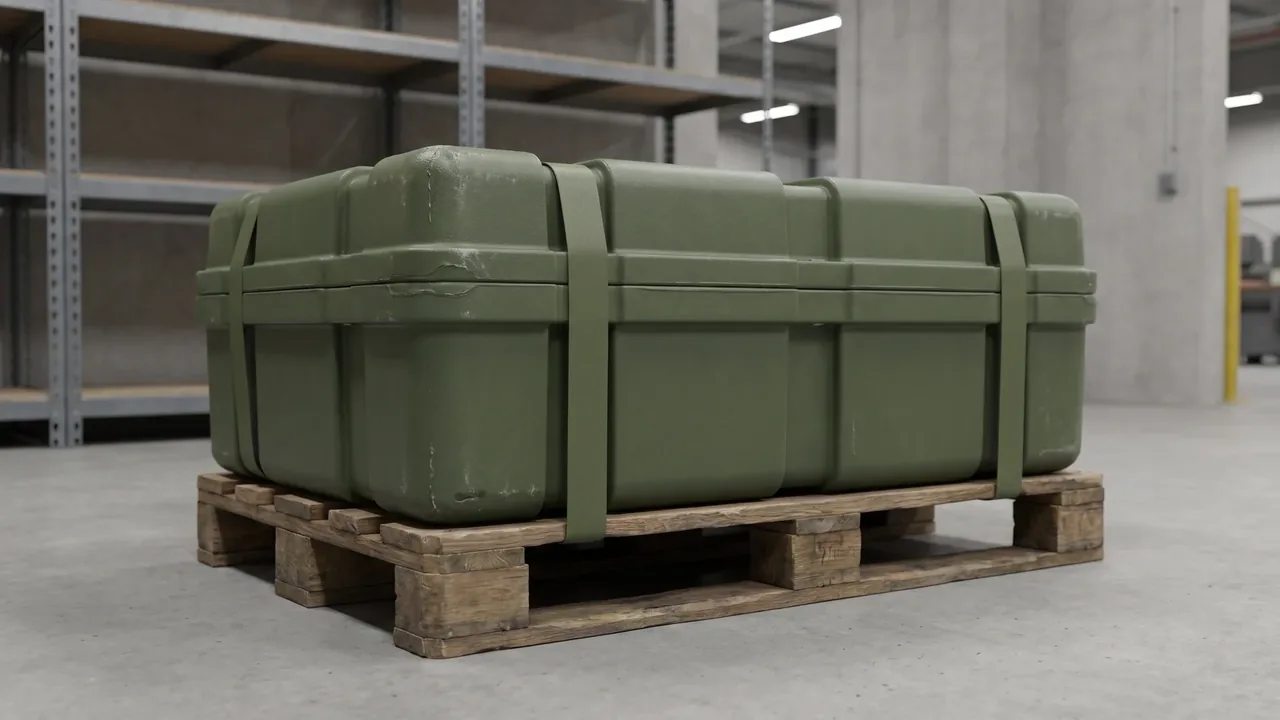
A fuze pack assembly, a propellant charge container and a projectile pallet can be bought as three separate line items and still fail as one system. The fuze pack assembly is the interface between a large count of small, light, contact-sensitive items and the line that consumes them. The propellant charge container is the moisture and contamination barrier for tubular parts. The projectile pallet is the heavy, load-bearing base that carries the batch and shapes how it fits into a container. Three different load regimes, three different failure modes, and yet they must share one dimensional chain, one stacking module, one handling interface and one traceability scheme. When they do not, the failure never shows up on any single drawing — it shows up at the first station of the assembly line.
This article looks at the three as packaging engineering: cavity liners and access control, sealing and moisture control, pallet load rating and load planning, and the kitting logic that delivers all three to the line together. Standards, certifications and export requirements vary by jurisdiction; this article discusses packaging containers only, and any project should be governed by local law and export control requirements. Nothing here concerns the construction, composition or performance of the items being packed.
Three Packaging Roles, One Dimensional Chain
Putting the three units on the same drawing starts with accepting that their load spectra are nothing alike. The fuze pack assembly carries many small, light items that are sensitive to impact and to contact with each other, so its central problem is separation: every item isolated in its own cavity, while the operator can still pull them in the right order and the right count. The propellant charge container carries tubular parts that are sensitive to moisture and contamination, so its central problem is isolation of a different kind: holding the internal environment apart from humidity, water vapour, particulates and pressure differentials. The projectile pallet carries the heaviest elements of the batch, so its central problem is support: spreading concentrated loads, passing stack load downward, and achieving the best possible utilisation inside a container.
Designed separately, the most common failure is not a bad component but a mismatched interface. The pack assembly height is not a multiple of the pallet stacking module, so the third tier sits on air. The container's sealing face conflicts with the lifting point, so a forklift can only approach from the wrong side. The pallet footprint and the pack footprint do not divide cleanly, so a mixed layer leaves gaps that no loading plan recovers. None of this is visible on a single-part drawing; it appears only when the three are checked against each other as a dimensional chain.
A kitted design therefore locks four shared parameters early: the footprint module, so all three tile the pallet cleanly; the stacking module, so mixed stacks still form a stable column; the handling interface, so forklifts, slings and manual short hauls use one set of movements; and the marking and traceability scheme, so a kit can be identified as a kit rather than as three unrelated batch numbers. Fixing these four at concept stage costs far less than reworking them after tooling. Pallet module planning is covered in more depth in case stackability and pallet planning.
Fuze Pack Assembly: Cavity Layout and Controlled Access
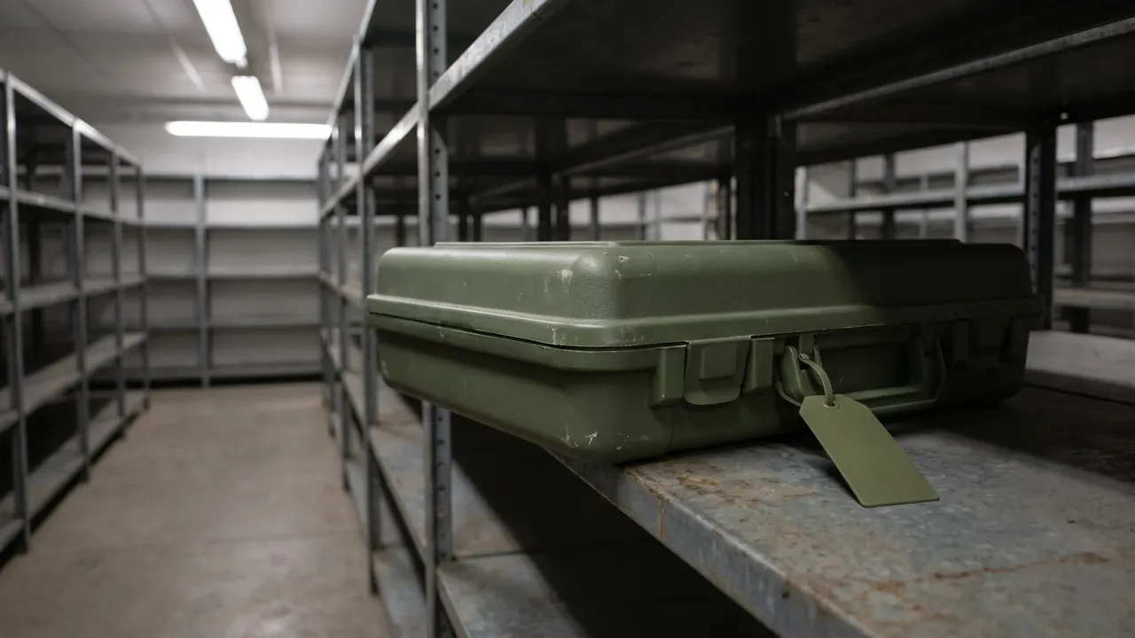
The cavity liner inside a fuze pack assembly is, in effect, a three-dimensional drawing that has been cut into foam. The shape, depth, draft and wall stiffness of every opening decide whether a small item is held firmly in transit or allowed to knock against its neighbour. Walls between cavities need real thickness; too thin and the liner collapses under vibration and lets neighbouring cavities merge. Too thick and internal volume is wasted, reducing how many items fit per case and increasing the number of shipments. Cavity depth is usually a little greater than item height, so that closing the lid produces a light pre-load without bottoming the item out against the cavity floor.
The most underrated part of cavity design is controlled access. A line operator wants to open the lid and take items top-to-bottom, left-to-right in assembly order, not dig around inside the case. A practical approach groups cavities by use, distinguishes the groups visually with a coloured liner face or a distinct opening profile, and leaves a shallow finger recess beside each cavity so an item can be lifted without a tool. That recess doubles as a count check: a supervisor can see at a glance which cavities have been emptied and how far the kit has been consumed. Liner material choice — EVA, polyethylene, flocked surfaces — matters as much as cavity profile, and is discussed in custom foam inserts.
Poka-yoke belongs to cavity design too. Where one line runs several parts that look similar but are not interchangeable, visual inspection rarely survives the pressure of cycle time. Making the cavity profile asymmetric, or making one corner cavity the only shape that accepts a particular part, converts "will the operator notice" into "the wrong part physically will not go in". That kind of mistake-proofing adds no packaging cost and saves a great deal of rework over the life of the kit.
Fuze Pack Assembly: Cushioning Liners and Energy Absorption
The job of a cushioning liner is to keep the acceleration that reaches a small item below what that item can survive — not simply to feel soft. Materials differ sharply in how they absorb energy. EVA rebounds well, can be reused many times and is available in a range of densities, which suits packaging that circulates. EPE is inexpensive with consistent single-trip performance, which suits one-way delivery. EPDM holds up better at low temperature and against ageing, which suits transport across climate zones. Layering two materials at different densities often beats any single material, because the softer outer layer absorbs the initial impact while the stiffer inner layer limits travel and provides support. The trade-offs are compared in internal foam types.
Cushion thickness should not be chosen by feel. It is derived from an assumed drop height and the maximum acceleration the item tolerates, then confirmed by a physical drop test. A common engineering approach is to assume a transport profile — handling drop, transfer toss, vehicle kerb — then read a material cushion curve for the density and thickness that meet it, and finally validate with real hardware. Two effects are easy to forget. Cushion performance drifts with temperature: cold makes many foams stiffer and less absorbing. And it drifts with loading history: repeated compression reduces rebound and support. For batches that ship across seasons or climate zones, the cushioning scheme should be checked at the low-temperature case, not only signed off at room temperature.
The liner-to-shell interface also needs design. A liner that slides directly on shell ribs will wear through its edges under sustained vibration; a thin backing sheet, or a liner edge that sits in a locating channel in the shell, solves both location and abrasion at once. Whether the lid-side liner is split or one piece depends on how often the case is opened: a split liner lets a worn layer be replaced on its own, while a one-piece liner opens and closes faster and keeps the sealing face more continuous. Pre-cut foam processing is covered in pre-cut foam liners.
Prop Charge Container: Gasket Sealing, Venting and IP Ratings
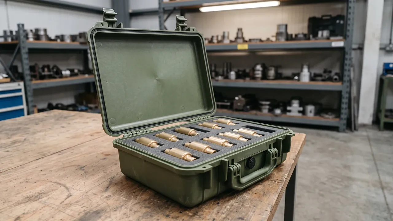
The heart of a prop charge container is the sealing interface. Gasket material is selected against service temperature range, contact media and compression set. Silicone covers a wide temperature band and stays elastic when cold; EPDM resists ageing and water vapour; nitrile grades handle oils better. Material choice matters less than groove geometry. Too much compression and the gasket loses its rebound in the cold and takes a permanent set under sustained load. Too little and it cannot stay in contact through the relative movement that vibration and thermal cycling impose on the shell. The groove must also leave room for the gasket to expand when compressed, so the elastomer is not squeezed into a space where it does not fit.
Whether the container needs a pressure equalisation valve depends on the transport route. When a container is closed in a warm, low-altitude environment and then meets low ambient pressure at altitude or a rapid temperature swing across a climate zone, the differential load stresses the shell and can lift the sealing face far enough to open a path. A vented container relieves that differential slowly while staying sealed in normal service. The valve should be placed away from positions where water pours or pools, and its port is normally built as a labyrinth or a diaphragm so gas passes while droplets and particles do not. If, on the other hand, the container must be hermetically sealed — for example filled with dry gas for long storage — no valve is fitted, and initial humidity is controlled in the closing process instead. The choice is a genuine trade between a container that can breathe and one that cannot.
IP ratings are the most misread specification in this category. The two digits describe dust and water performance measured under standard test conditions; they do not promise that a container stays dry in any attitude, depth or duration. For long outdoor storage, look past the rating at whether sealing faces will be affected by mud, salt spray or ice, and whether closures, latches and hinges meet the same standard as the main seal. A thick shell with a heavy main gasket whose latches leak is the classic failure mode of this container type.
Prop Charge Container: Desiccants, Humidity Indicators and VCI
Sealing decides whether the container can exchange with its surroundings; the moisture control system decides how long the inside holds. Desiccant quantity should be calculated from free internal volume, the moisture already held in the packaging materials, expected storage duration and external humidity — not chosen by habit. Silica gel absorbs strongly, costs little and can be supplied with a saturation indicator; molecular sieve performs better in the low-humidity range where residual moisture limits are tight. Desiccant has to sit where air can reach it, not all packed into one corner. If the interior is divided by liners into spaces that do not communicate, each space needs its own moisture capacity.
Humidity indicator cards are the cheapest and most effective inspection tool in the system. They let an operator judge whether internal humidity is still acceptable without opening the container, and they show during long storage whether desiccant needs replacing. The card should be fixed where it is immediately visible on opening, and its replacement interval should be written into the maintenance procedure alongside the desiccant.
VCI, vapour corrosion inhibitor, is used here to protect the container's own internal metal parts — latches, hinges, liner fixings, metal backing plates. VCI material releases a corrosion-inhibiting vapour inside a closed space and forms an extremely thin protective layer on metal surfaces, suppressing rust in humid conditions. Combining VCI with desiccant is a common approach for metal parts stored long-term in humid climates. It is worth noting that more is not better: excessive desiccant can accelerate the loss of some inhibitor vapours, and some non-metallic materials are not compatible with inhibitor chemistry, so material compatibility should be confirmed before the scheme is fixed. The complete moisture system should be checked together with the seal rating, not item by item.
Projectile Pallet: Load Rating, Supports and Load Distribution
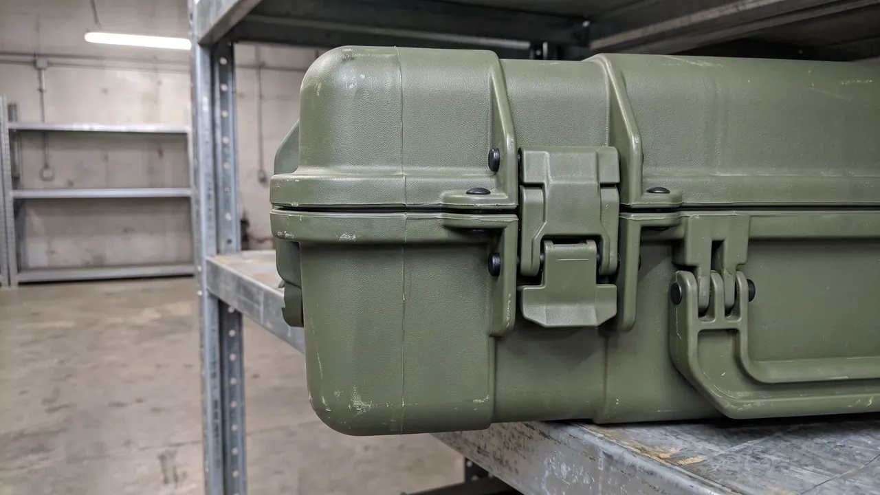
The projectile pallet is the only one of the three that carries the full weight of the batch directly, and its design logic is the opposite of a case: a case resists impact and puncture, a pallet resists deflection and fatigue under sustained static and dynamic load. Pallet material may be hardwood, plywood, engineering plastic or a steel frame, and selection depends on three figures at once — static rating, dynamic rating and allowable deflection — rather than on a single "how much can it hold" number. Static rating is the load a pallet carries while standing still under a stack; dynamic rating is the load it carries during forklift handling and vehicle transport, and is typically about half the static figure or less. Allowable deflection is how far the centre is permitted to sag under load; too much sag tilts the layers above, loosens strapping and shifts the stack's centre of gravity.
How the load is distributed across the pallet matters more to its service life than the total load. A concentrated load, such as four heavy cases on four corners, bends and can punch through the deck boards; a distributed load spreads force through deck, blocks and stringers to the forks or the floor. This is why deck spacing, block positions and stringer sections should be designed together with the case support points — case supports should land on a pallet support line, not in the gap between two lines. For heavy, high-centre-of-gravity cargo, locating stops or recesses in the deck keep the case from sliding relative to the pallet during handling.
The underside needs design as well. Fork entry height, width and spacing should be reserved to suit the forklifts that will actually be used, and entry openings should be chamfered so repeated entry does not chew the timber or plastic. Where cargo must be lifted by sling, the pallet should have sling openings or lifting points positioned so the pallet does not tip during the lift. Load capacity should be fixed to the pallet on a plate showing static rating, dynamic rating, tare weight and permitted handling methods. Over many trips that plate is often more reliable than the drawing, because the forklift driver on site only ever sees the pallet.
Projectile Pallet: Dimensional Chain and Container Utilisation
Once the pallet is fixed, the case dimensions are no longer free. Load planning has to solve the case-to-pallet-to-container chain in a single pass, so each level divides the one above into whole numbers rather than being patched together at the container door. The first step lays the case footprint onto the pallet and checks for overhang — anything hanging past the pallet edge is carrying load on nothing, which both crushes the case and moves the stack's centre of gravity outward. The second step multiplies by tiers and checks the total stack height against the usable internal height of the container, leaving handling clearance. Only the third step checks weight, because in this cargo class space usually runs out before payload does.
The most overlooked part of load planning is the mixed-load rule. When one container holds fuze pack assemblies, propellant charge containers and projectile pallets together, their unit weights and centre-of-gravity heights differ widely. Putting the heaviest, lowest and stiffest units on the bottom and the lighter units above is a sound default, but it is not enough on its own: each layer must also be loaded evenly, so that no isolated heavy column rises through one side of the container. Where the load really must be split into zones, separate the zones with strapping or partitions so they cannot press against each other in transit. Load planning rules are developed further in case stacking structure and in dividers versus foam.
The container door is the last and most easily forgotten check. A load that fits the internal dimensions but not the doorway gets re-stacked in the warehouse. Palletised loads also need allowance for structural variation at the front of some containers and for local floor unevenness, bridged with packing boards where level loading matters. The finished load plan should exist as a page-by-page loading drawing showing orientation, count, strapping positions and centre-of-gravity height for every tier, so the crew works to a drawing rather than to habit.
Stacking the Three Together: Column Stability and Compression
When all three packaging types are stacked together, the stability of the whole stack is set by its weakest link. A stacking check asks three questions. Can the bottom unit carry everything above it? Will an intermediate unit creep and collapse under long compression? Will the stack slide or topple under dynamic transport load? The first is answered by a compression test, normally by loading the bottom unit to the equivalent static load for the intended height and duration and inspecting for permanent deformation. The second depends on the creep behaviour of the material: plastics and foams deform slowly under sustained load, so a short room-temperature test passing does not mean a long storage period will pass. The third is solved by interlocking features and strapping working together.
Interlocking features locate each tier against the one below and stop sideways slip. Practical options include matching raised and recessed profiles on lid and base, or shallow locating recesses in the pallet deck that match the case base. Strapping then restrains the stack as a single body, so dynamic load is shared rather than concentrated on one case. It is important to be explicit that stretch wrap and strapping restrain; they do not support. They cannot substitute for the load capacity of the bottom unit, and they cannot close a gap in the dimensional chain.
Stacking rules should also distinguish like-on-like from mixed stacking. With identical units the module is uniform and the load path is clear, so the rule can be relatively permissive. With mixed units the stiffness, height and footprint all differ, so each tier must be checked and the loading drawing must state the combination, the levelling method and the strapping positions for every layer. For stacks stored long-term, floor capacity, rack beam capacity and ambient temperature and humidity belong in the calculation too. Stackability is not a property of the packaging alone; it is a system property of packaging, pallet, floor and environment together.
Lifting, Fork Handling, Locks and Seals
Every time a kitted set is picked up, one handling interface does the work. Palletised loads rely mainly on the fork entry, so that opening is the core interface. Single units and small transfers may be moved by hand, so handles, grips and ergonomics become the interface. Heavy units may need slinging, so sling openings, lifting eyes and lift-point marking have to line up with the unit's centre of gravity. If the three packaging types each demand a different handling method, the site needs different attachments, different training and different procedures, and both efficiency and safety suffer. Standardising on a small number of handling methods is the most immediately valuable part of a kitted design.
The most common lifting error is placing lift points away from the centre of gravity. The unit tilts as it leaves the ground; at best the contents shift, at worst a sling slips free. Correct positioning puts the resultant lift line through the centre of gravity, or marks the centre of gravity and the recommended sling angle on the unit so the crew can follow it. Sling contact with edges should be protected with corner guards or sleeves so the sling cannot be cut. For units and pallets that circulate, the exterior should carry the rated load and the permitted number of stacked tiers, so every lift can be made correctly without opening a drawing.
Locks and seals answer a different question: who opened this, and when. Mechanical locks, hasp-and-staple latches and one-trip seals suit different levels of control. A seal provides irreversible evidence of opening, which suits one-way delivery and handover. A mechanical lock suits a returnable container opened repeatedly. A numbered seal combines physical security with a record. Seal numbers should be written onto the transfer document associated with that kit, and on opening the receiver checks that the numbers are continuous and unreplaced. For kits that deliver all three packaging types together, the seal numbers are best issued as one group, so the receiver can see at a glance whether the set is complete. These interfaces sit naturally alongside ammunition transport box certifications.
Kit Delivery Logic at the Assembly Line
The point of kit delivery is that the three packaging types arrive as a kit, not as three separate shipments of cases. That requires the packaging design to fix, up front, how many pack assemblies, how many charge containers and how many pallets make up one kit, and to hard-code that quantity relationship into the marking and the traceability code. When the line runs a given number of kits per hour, line-side stock should be managed in kits rather than in pieces, and the replenishment trigger should fire on kits. If any one type runs out, the whole line's supply of kits stops, and replacing the missing type alone does not restart it.
How the kits are presented line-side is part of the same design. Units should reach the line with the fewest possible handling steps, which means sizing them to go straight into a line-side rack or kanban position and making open, take and return a one-person operation. Returnable units should be designed to fold or nest so that empty containers take as little volume as possible on the way back, which drives the economics of the returnable loop directly. One-way units should be judged on how easily they open and how easily they are disposed of.
Kanban pull places demands on how visible the packaging is. Because the signal comes from line-side consumption, every unit needs clear, distance-readable marking of the item number, quantity per kit and reorder point. If units carry RFID or QR codes, line-side consumption can be captured automatically and the replenishment signal moves from a person reporting to a system reporting, which reduces both stockouts and overstock. But automated traceability assumes consistent tag placement: if each batch puts the tag somewhere different, read rates drift by batch. Kit delivery and packaging coding should follow the marking requirements set out in metal ammunition container specifications and ammunition packing box standards.
Materials and Certification: GJB, MIL-STD-810H, UN and Export Packaging
Material selection for a packaging container has to meet mechanical, environmental and compliance requirements at the same time. The mix of engineering plastic, steel, aluminium, timber and composites sets shell strength, weight and weather resistance; the liner material sets cushioning and separation; the seal material sets the protection rating. These three cannot be chosen independently. A shell that is too stiff with a liner that is too soft passes impact straight through to the contents; a shell that is too soft with a liner that is too stiff deforms the shell first. The sound approach is to set a shell stiffness target first, then choose liner density and thickness against it, so that the impedance rises step by step along the whole cushioning chain.
On certification, Chinese military packaging commonly applies the GJB series for environmental suitability and test methods, covered in more detail in GJB military standard cases. Packaging for export or multi-country transport is often validated against the drop, vibration, shock, rain and temperature methods in MIL-STD-810H. Packaging that falls into a regulated transport category must also complete design qualification and testing against the applicable UN packaging requirements. It is worth stressing that UN packaging certification applies to the transport package as a whole, not to a material or a single part; after design qualification, a change to shell structure, liner scheme or closing method usually requires reassessment.
Validation typically covers drop, stacking compression, vibration, rain or immersion, thermal cycling and IP rating tests. The purpose of testing is not to pass once but to confirm that the design has margin under its intended service conditions. The test matrix should therefore cover the worst case: heaviest contents, lowest temperature, longest transit duration, worst stacking combination. All test results, material certificates and structural change records should be archived as a traceable packaging technical file. To repeat the point: this article discusses the design, testing and certification of packaging containers only, and every project should be governed by local law and export control requirements.
RFID Traceability and Batch Management
Once a packaging unit reaches the assembly line it stops being a container and becomes an information carrier. An RFID tag, a QR code and a printed batch number together answer who made this packaging, what it holds, when it arrived and where it was last. RFID reads many units at once without contact and without opening the package, which suits automatic capture as a full stack passes a gate. Its weakness is interference: metal and liquids shorten read range sharply, so tag position has to be fixed at design stage and validated with a real read-rate test.
The physical durability of a tag matters as much as its data. Friction in transit, rain, cold and washdown can all detach or disable a tag, so tags should be embedded or over-laminated at a fixed position rather than stuck on temporarily. On returnable units, the tag position is best made a defined recess or marking area, so replacement tags do not wander. Batch management requires that the packaging batch number can be traced back to the batch of its contents without printing sensitive detail on the outside of the case; an internal code linked to a database meets the traceability requirement while keeping information exposure controlled.
Traceability only earns its cost when the loop is closed. If the code is scanned at goods-in but not at goods-out, the data chain breaks in the middle; if only the last position is recorded, nobody can answer who opened the unit in between. Packaging design and process design therefore move together: seal numbers, RFID tags, transfer documents and opening records should share one coding rule and join up in one system. For kits that deliver all three packaging types, traceability should support both a by-kit and a by-unit query — the first for bulk handover, the second for fault isolation.
Common Design Faults and a Pre-Production Checklist
Before tooling is released, running all three packaging types through a single checklist catches most late rework. The faults below are the ones that recur most often.
- Open dimensional chain: case footprint, pallet footprint and container internal width were never divided into whole numbers. Action: produce a one-page loading drawing with per-tier layout and clearances.
- Mismatched stacking module: mixed stacks do not share a height module, so upper tiers sit on air. Action: unify the module, or state a levelling method on the loading drawing.
- Cushioning checked at room temperature only: foam stiffens and absorbs less when cold. Action: re-check cushion thickness at the lowest service temperature.
- Sealing judged by the main gasket alone: latches, hinges and valves become water paths. Action: rain or immersion test every opening individually.
- Moisture control judged by desiccant quantity alone: divided interiors block airflow and leave hot spots. Action: place desiccant and indicators per cavity.
- Pallet judged by static rating alone: dynamic rating and allowable deflection were never checked, so the deck sags over time. Action: select by dynamic rating and re-measure deflection on a used pallet.
- Lift points off the centre of gravity: the lift tilts and slings cut into edges. Action: mark the centre of gravity and the recommended sling method, and fit corner guards.
- Traceability tag placement left to chance: read rate drifts by batch. Action: fix the tag position and audit read rate on samples.
- Testing signed off on a single pass: the worst case was never covered. Action: build the test matrix around heaviest, coldest, longest and worst-stacked.
- Changes made without reassessment: liner or closing method changed while the original certification was carried over. Action: create a structural change review gate and re-test where needed.
Fuze Pack Assembly — Frequently Asked Questions (FAQ)
Q: Is more cavities always better in a fuze pack assembly?
A: No. The cavity count follows the number of items to be packed, the item geometry and the minimum spacing that must be kept between adjacent items — not a general preference for safety. Packing cavities too closely thins the walls between them, so the liner can collapse under vibration and let neighbouring cavities merge. Spacing them too widely wastes internal volume, lowers how many items fit per case and increases the number of shipments. The practical route is to fix the minimum cavity pitch from item geometry and cushioning needs, then solve for the largest number of cavities that fits the available internal volume, leaving at least one finger recess and one count check position. Once the count is set, validate with a physical vibration and drop test at both full and partially emptied states, because the partially emptied case is often the weaker structure.
Run the trade-off on a loaded sample rather than on paper: more cavities mean more walls, more contact points and more places for a liner to wear, while fewer cavities concentrate load and make partial depletion obvious. Check handling with one compartment empty and one fully loaded, since real fleets rarely run uniform for long.
Q: For a fuze pack assembly liner, should I choose EVA or EPE?
A: Neither is universally better; the decision follows circulation count and delivery model. EVA rebounds well, survives repeated use and is available in a range of densities, which suits packaging that is opened and reused many times, and its whole-life cost is lower in that role. EPE is inexpensive with consistent single-trip cushioning and good batch-to-batch uniformity, which suits one-way delivery where the packaging travels with the goods and is then disposed of. If delivery crosses climate zones, low-temperature performance belongs in the comparison, because some materials stiffen noticeably and lose absorption when cold. In practice a common scheme layers the two: a softer outer layer absorbs the initial impact while a stiffer inner layer limits travel and provides location, so cushioning and positioning are both satisfied.
A practical pattern is EVA in the cells that carry weight and locate parts, with EPE where the task is pure deceleration, and a laminated combination where both roles meet. Ask how often the pack circulates: a daily-use kit rewards a firmer, more abrasion-resistant surface, while a once-a-year shipment can afford softer, cheaper foam.
Q: Does a prop charge container always need a pressure equalisation valve?
A: No, and the answer depends on the transport route and the storage requirement. When a container is closed in a warm, low-altitude environment and then meets low ambient pressure at altitude or a rapid cross-zone temperature swing, the differential load stresses the shell and can lift the sealing face far enough to open a path, and a valve is advantageous in that case. Conversely, if the container must be hermetically sealed, for example filled with dry gas for long storage, no valve should be fitted, and initial humidity and residual air are controlled in the closing process instead. Neither route is inherently better; the choice is a trade between a container that can breathe and one that cannot. Whichever is chosen, valves, latches and hinges should each be rain or immersion tested separately, rather than validating the main gasket alone.
Where the route includes altitude change or large diurnal swings, fit one and test it as part of the container rather than as an accessory. Where the route is short, sealed and temperature-stable, the gasket alone may suffice, provided the closure is validated by the same pressure cycling the real journey implies.
Q: Is a higher IP rating always better for long-term outdoor storage?
A: Not in a simple sense. An IP rating is measured under standard test conditions; it describes how well the container resists dust and water in that condition, and it does not promise that the interior stays dry in any depth, duration or attitude. Long outdoor storage also depends on whether sealing faces are affected by mud, salt spray or ice, whether openings such as latches meet the same standard, and how materials age under ultraviolet light, thermal cycling and time. For a container intended for long storage, look beyond the two digits at the sealing integrity of the whole structure, the protection offered by valves and locks, and serviceability — whether a gasket can be replaced without destroying the seal. A combined assessment is more reliable than any single figure.
Real exposure rarely matches the test rig: driving rain at an angle, standing water, ice and years of UV all attack different details of the closure. Specify the rating the scenario needs, then verify the details the rating does not cover — drain paths, hinge lands, label adhesive and the gasket itself — with a test plan that mirrors the actual service environment.
Q: What is the difference between a pallet's static rating and its dynamic rating?
A: Static rating is the load a pallet can carry while standing still under a stack; dynamic rating is the load it can carry during forklift handling and vehicle transport. Because transport involves acceleration, braking, cornering and road unevenness, a pallet in service is carrying a dynamic load, and the dynamic figure is typically about half the static figure or less. Selection must therefore be made on the dynamic rating, and the allowable deflection must be checked as well — that is how far the centre of the deck is permitted to sag. Excessive sag tilts the layers above, loosens strapping and shifts the stack's centre of gravity, and over many trips it fatigues the deck. Fit a plate to the pallet showing static rating, dynamic rating, tare weight and permitted handling methods so the decision can be made on site.
For packaging the dynamic figure is the one that matters, because every journey adds vertical acceleration to the standing load. Ask the supplier for both numbers, together with the test conditions behind them, and keep a margin between the rated figure and the real stacked weight so handling variation never consumes the whole allowance.
Q: When the three packaging types are stacked together, how should the stacking order be set?
A: The basic rule is to put the heaviest, lowest and stiffest units at the bottom and the lighter units above, so load travels down the strongest path. That rule alone is not enough. Each layer must also be loaded evenly, avoiding an isolated heavy column rising through one side, because a local concentrated load can overload the bottom unit even when the total weight is within rating. Where the units differ in stiffness, height and footprint, every tier must be checked, and the loading drawing must state the combination, the levelling method and the strapping positions for that layer. A mixed stack's height is normally limited by its weakest element, so the whole stack should also be tested at its rated static load to confirm that the bottom units show no permanent deformation over the intended storage period.
Then check the interface: a stiff pallet on soft cases, or the reverse, creates a point load that neither datasheet describes. Interleave with load-spreading boards where the contact areas differ, and confirm the arrangement with a trial stack loaded to the real weight, held long enough to reveal creep.
Q: Where should the lift points on a packaging unit be placed?
A: The first principle is that the resultant lift line must pass through the unit's centre of gravity, otherwise the unit tilts as it leaves the ground — at best the contents shift, at worst a sling slips free. There are two practical approaches. One places lift points symmetrically about the centre of gravity so the resultant naturally passes through it. The other marks the centre of gravity and the recommended sling angle on the outside of the unit and relies on the crew following the marking. Either way, sling contact with edges should be protected by corner guards or sleeves so the sling cannot be cut and fail suddenly. For units and pallets that circulate, the exterior should also state the rated load, the permitted number of stacked tiers and the permitted lifting method, so each lift can be judged without opening a drawing.
Mark every lifting point clearly, pair it with the permitted rigging, and repeat the marking on both long faces so a crane crew never has to guess. Where a case can be lifted by forklift as well as crane, keep the two interfaces far enough apart that neither undermines the other.
Q: In kit delivery, should the kanban signal fire per kit or per piece?
A: It should fire per kit. The underlying logic of kitting is that the three packaging types reach the assembly line as kits, and if any one type runs out, the line's supply of kits stops; replacing the missing type alone does not restart it. Line-side stock should therefore be managed in kits, and the reorder point set in kits, so that when the available count of any one type falls below its threshold the whole kit replenishment is triggered. To make by-kit management workable, the marking must hard-code the quantity relationship within a kit and line-side consumption must be captured quickly. If RFID or QR codes are used, the signal can move from a person reporting to a system reporting, reducing both stockouts and overstock — provided tag placement is consistent and read rates are stable.
Related Reading