

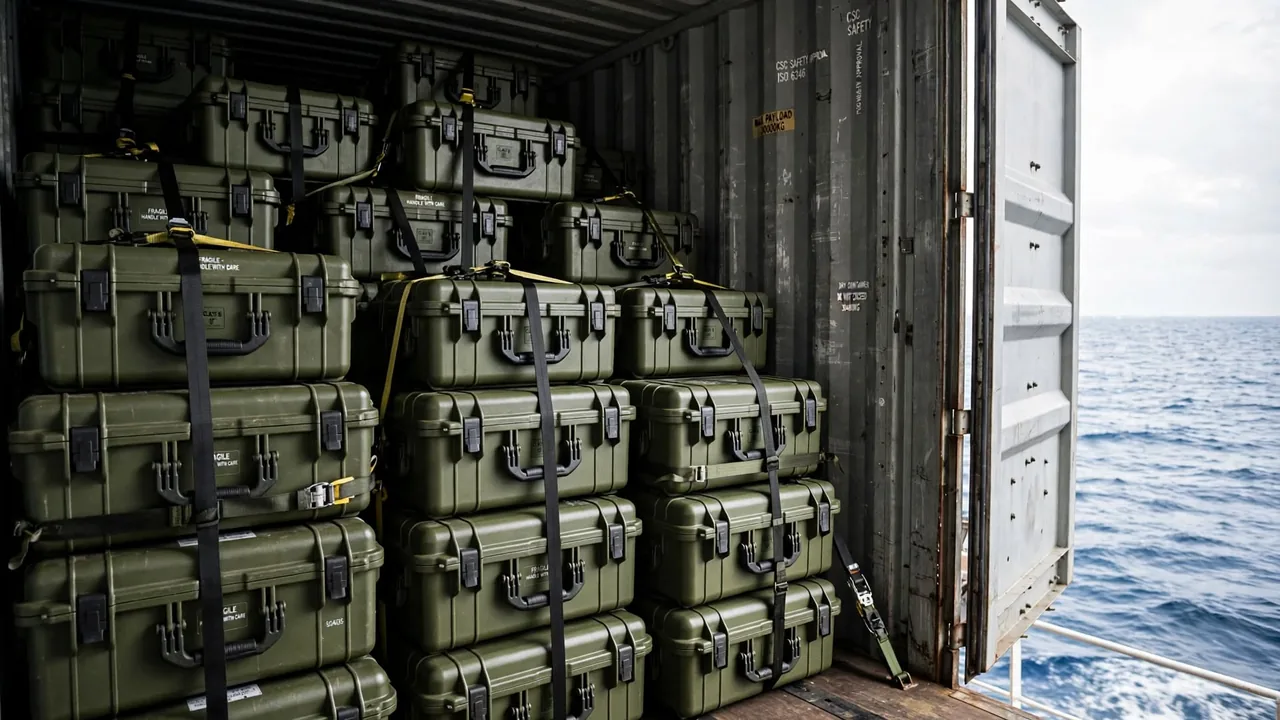
Offshore equipment lives inside an atmosphere that is hostile in a very particular way. Air above open water carries fine droplets of sodium chloride, and wherever those droplets settle they leave a thin film of electrolyte that keeps electrochemical reactions running even when nothing is actually submerged. Deck spray, wash-down hoses, condensation driven by day-to-night temperature swings and months of ultraviolet exposure all act on a marine engineering protective case at once. The two failure routes that matter most are corrosion of the metallic hardware and water finding its way past the seal. Neither can be solved by a single material decision, because a shell that resists salt may still be defeated by a latch that rusts or by a gasket groove that quietly collects brine.
This article works through the container itself. It covers shell materials, coating systems, the rules for pairing dissimilar metals, seal geometry, salt-fog and immersion verification, and the practical business of moving and stacking cases on a working deck. It is written for engineers and buyers who have to specify a case that will still open freely after a season at sea, and for maintenance teams who must keep existing cases serviceable. Where a subject deserves deeper treatment, links point to the relevant companion guide. Throughout, the focus stays on the container structure and on the protection it provides, not on whatever is placed inside it.
A useful way to approach the problem is to separate it into two layers. The first is material behaviour: which alloys and polymers survive chloride exposure, how coatings and surface treatments slow attack, and why mixing metals is usually the fastest route to premature failure. The second is geometry: how a gasket is compressed, where water is likely to pool, how a lid flexes under load, and how a case behaves when it is dropped, lifted or stacked. Most field failures trace back to one of these two layers rather than to an exotic chemical attack. Getting both right is what separates a case that merely looks rugged from one that keeps a dry interior through repeated voyages.
Finally, it is worth remembering that verification is part of design, not an afterthought. A specification that names a test, a depth, a duration and an acceptance criterion is far more useful than one that simply promises salt resistance. The sections that follow give the reasoning behind each of these points and end with a short procurement checklist and a note on the boundaries of what a container article can and cannot conclude.
1. Why Offshore Work Corrodes Cases Faster and Lets Water In
The air above open water holds fine particles of sodium chloride. When they settle on a metal surface they dissolve in the microscopic film of moisture that is almost always present, and that film becomes an efficient electrolyte. From that point onward a corrosion cell can operate continuously, even on a component that never touches the sea. Offshore duty adds several loads on top of this baseline. Breaking waves deliver spray at pressure; wash-down hoses soak every crevice on a regular schedule; night-time cooling pulls condensation onto cold metal; and unfiltered sunlight slowly breaks down polymer shells and hardens rubber seals. Each mechanism targets a different part of a marine engineering protective case, which is why a design that looks sound in an inland warehouse can fail within a single season at sea.
Water rarely enters through dramatic damage. More often it creeps in through screw holes, handle bosses, pressure-equalisation valves and the corners of a gasket, over weeks rather than minutes. By the time someone notices dampness, a layer of brine may already have spread across the interior. Once liquid is trapped inside, salt keeps cycling between wet and dry states as temperatures change, and the corrosion rate climbs sharply. Pitting then appears on otherwise protected surfaces, and fasteners begin to seize in their threads.
Ultraviolet radiation is a second, quieter threat. It chalk the surface of a plastic shell, reduces impact strength, and hardens elastomer seals until they stop springing back. A gasket that compressed correctly when new may take a permanent set within a year, and the loss of rebound is invisible from outside. Humidity inside a closed cabin compounds the problem by encouraging mould, whose metabolic by-products are themselves mildly acidic. Together these effects explain why corrosion and ingress are usually simultaneous rather than separate events. Inspection routines should therefore examine seals and metal hardware at the same time, and salt-fog testing offers a structured way to compare candidate designs before they ever reach a vessel.
2. Choosing Case Materials: Stainless Steel, Aluminium or Engineering Plastics
The material choice sets a ceiling on how well a case can resist salt, and it also decides how hard the case will be to maintain. Austenitic stainless steel is not automatically immune to chloride attack: grades without molybdenum are prone to pitting and crevice corrosion when they sit in sea air for long periods, while the more resistant grades carry both a weight and a cost penalty that becomes awkward when the case is carried by hand. Aluminium is lighter and easier to handle, but its natural oxide film is fragile in chloride environments. Once that film is broken at a sharp corner or around a fastener hole, corrosion drives inward rather than spreading harmlessly across the surface, which makes anodising or a coating system essential rather than optional.
Engineering plastics and glass-fibre composites behave differently because they take part in almost no electrochemical reaction. That makes them attractive for weight-sensitive equipment that is moved often. Their weakness is environmental rather than chemical: prolonged ultraviolet exposure chalk the surface and lowers impact strength, and cold weather can make some grades noticeably brittle. Designers therefore have to weigh equipment mass, handling frequency, whether metallic shielding is required, and how easily the case can be repaired, instead of comparing unit prices alone.
A practical compromise is to treat different areas of the same case differently. Load-bearing structures and permanently exposed parts can use a more corrosion-resistant material, while lids and dividers that must stay light can be moulded from engineering plastic. Where metal and plastic meet, insulating elements should separate them so that a galvanic couple never forms. This layered approach usually costs less than building the entire case from premium stainless steel, and it keeps maintenance focused on a small number of critical parts. Weight also has to be weighed against the manual-handling limit that applies on board, because a case that is theoretically superior may never be used if two people cannot lift it safely onto a deck. A short handling trial with the actual equipment, done aboard the vessel rather than in a showroom, is worth far more than a spreadsheet comparison. Further reading on shell construction and wall-thickness trade-offs is available in the shell selection guide, which covers stiffness and weight balance in more detail.
3. Surface Treatment and Coating Systems That Slow Salt-Fog Attack
Whether a metal part survives at sea depends heavily on whether its surface treatment system is complete. Anodising grows a relatively dense oxide layer on aluminium, but if the film is too thin it will still be consumed in salt fog, so sealing quality and film thickness belong in the drawing rather than in a verbal promise. Stainless components that are only mechanically polished have a less uniform passive film; electropolishing or acid passivation usually improves pitting resistance noticeably. For carbon-steel fasteners, a multi-layer scheme is more dependable: a phosphate or zinc-flake base coat followed by a topcoat suited to marine climate, with enough film thickness even at thread roots, because that is where corrosion frequently begins and where it is hardest to see.
In coating work, the cleanliness and roughness produced by surface preparation often matter more than the paint itself. Residual salt or oil causes blistering and flaking at a very early stage, so rinsing and drying should not be compressed to save schedule time. Film-thickness checks need to be taken region by region; a flat panel that passes inspection does not prove that a corner or a weld is equally protected, yet those are exactly the places where attack starts first. Coating systems are also best judged together with environmental testing, because cyclic salt fog and humidity cycling reveal early failures that a single check can miss. Another practical point concerns dissimilar finishes on the same case. If a coated steel bracket sits beside an anodised aluminium panel, the two treatments age at different rates, and the joint can turn into a moisture trap once the first of them fails. Keeping the finish schedule simple, and roughly matched in expected service life across a joint, avoids the situation where one material is still protected long after its neighbour has been breached. Repair has to be planned as well: a coating that can be touched up by hand on board is far more useful than one that demands a workshop visit. Practice in petrochemical and coastal heavy-corrosion settings offers useful parallels, and the notes on coating selection in the coating practice reference describe compatible systems in more depth.
4. Galvanic Corrosion and the Limits of Mixed-Metal Hardware
Whenever two metals of different potential touch inside the same electrolyte, galvanic corrosion begins and the less noble metal becomes the anode and dissolves preferentially. Sea air provides an almost ideal electrolyte, so mixed-metal construction on a case deserves strict attention. Stainless screws threaded directly into an aluminium frame, zinc-plated steel parts pressed against stainless plate, and carbon-steel lifting lugs bolted to a stainless shell are all classic accelerating combinations. Nothing may look wrong for a while, and then white corrosion products and deep pits appear after a few months of service.
The standard countermeasure is to break the electrical path with insulating washers or sleeves between dissimilar metals, and to make sure that liquid cannot remain standing on the joint. Geometry matters as well: keeping the anode area small and the cathode area modest reduces attack, because a large cathode driving a small anode produces an extremely high local dissolution rate, and a single screw hole can be eaten through in a short period. Assembly conditions change the outcome too. Working in damp weather can seal moisture into a joint, so critical assemblies are better built in dry conditions with a sealing compound that also prevents thread galling.
If mixed metals are unavoidable, the drawing should state the grade, the contact method and the tightening torque for each metal part, along with any earthing or insulation requirement. Treating the topic as a design input rather than a shop-floor improvisation is the cheapest protection available. Threaded connections deserve particular care, because the contact area inside a thread is large and almost impossible to inspect, and moisture that creeps into it can start attack that stays invisible until the fastener is removed. Specifying a sealing compound, a controlled torque and, where appropriate, a nylon or fibre washer isolates the joint both electrically and mechanically at the same time. A parallel discussion of earthing and metal compatibility appears in the utility enclosure design reference, which is a useful comparison for offshore metal structures.
5. Sealing Structure: Gaskets, Grooves and Compression Force
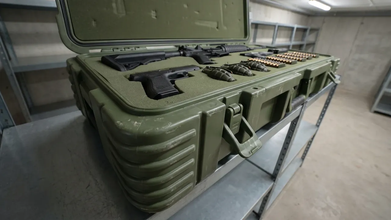
The seal is the most direct line of defence against water, and its reliability is decided by three things working together: gasket material, groove shape and compression force. Ethylene-propylene-diene rubber and silicone are common choices offshore because they tolerate ozone and ultraviolet reasonably well and stay elastic at low temperature. Neoprene resists oil better but ages faster in strong sunlight, so it needs more frequent inspection. The groove must produce even compression when the lid closes. Too little compression leaves a path for water; too much accelerates permanent deformation, and after a handful of opening cycles the gasket can no longer return to its original sealing height.
Lid stiffness matters just as much. If a cover flexes under load, the gasket in the middle of a long span lifts away from its land and creates an ingress point that is almost impossible to spot by eye, which is why large cases often need stiffening ribs on the inside of the lid. Corners are the weakest zone of any seal, so gasket joints are normally moulded as one piece or scarfed rather than simply butted, since tension and squeeze both concentrate at the turn. Screw spacing should match gasket hardness; when fixings are too far apart, the clamping force between them is insufficient and spray will find its way in.
Routine inspection should look for hardening, deformation and embedded grit, which reveal far more about the real condition of the seal than the appearance of the case as a whole. Spare gaskets also deserve proper storage away from heat and light, because a new part that has aged on a shelf may have already lost part of the elasticity it was chosen for. Where a case is opened frequently in service, a compression-set measurement taken during routine maintenance gives an early warning that a seal is approaching the end of its useful life. A simple reference mark on the gasket land also helps an operator see whether the lid is seating as it did when the case was new. The seal strip guidance reference examines material options and replacement criteria in more detail.
6. Immersion and Spray: Quantifying the Sealing Boundary
Whether a sealing boundary is trustworthy is ultimately a question for testing rather than for feel. An immersion test submerges the case to a defined depth for a defined period and then checks the interior for water and condensation. A spray test directs water at a set pressure at the lid, imitating deck wash-down and heavy rain, and concentrates on gasket corners and fastener holes. The two procedures expose different failure modes: immersion stresses the seal under static head, while spray stresses weak points under moving water. Running only one of them leaves a substantial part of the risk uncovered.
For offshore duty, the sequence often has to be repeated at low temperature, because rubber stiffens in the cold and sealing ability falls with it. A case that passed in summer is not automatically reliable in winter. After testing, the useful record describes where water entered, how much arrived and how the seal recovered, not merely a pass or fail verdict. That kind of detail is what allows a design to be corrected instead of replaced. Sample assemblies should also match production conditions as closely as possible, since a carefully hand-built sample usually outperforms the real product and can flatter the design.
Where conditions allow, a leak or pressure-decay check before and after the test on the same case reveals whether the seal structure took a permanent set under load. Recording ambient temperature, duration and recovery time for every test produces a traceable file that lets different production batches be compared fairly. For equipment that must stay sealed over many years, repeating the test on a production sample at intervals is a useful habit, because seals age in storage and in service rather than only in the laboratory. Taking one case from each batch and running the immersion sequence again catches slow drift in the moulding process that a single type test would never reveal, and it builds a history that supports better maintenance planning. For details of depth, duration and acceptance criteria, see the notes on immersion testing.
7. Reading Dust and Water Ingress Ratings for Marine Duty
An ingress protection rating uses two digits to describe resistance to solids and to liquids, but the digits only mean something when they are read against the real duty. Offshore work mainly involves continuous splash, short-term immersion and high-humidity condensation, so the second digit deserves the closest attention. The first digit still matters for keeping dust and salt crystals out of latches, because salt that accumulates inside a mechanism accelerates wear and can jam it.
A case rated for short-term immersion is not automatically safe for prolonged immersion, and it is certainly not proof against moisture drawn in when the temperature changes and the pressure inside falls. That is why the selection of the pressure-equalisation valve becomes important. A valve with too little airflow forces the case to breathe repeatedly as temperatures swing, pulling humid air in a little at a time, while a valve with too much airflow weakens the water barrier. The right balance depends on internal volume and how the case is used.
Above all, a rating is a laboratory result. Assembly quality, gasket condition and hardware sealing can all push field performance below the declared figure. Treating the rating as a starting point rather than an endpoint, and pairing it with scheduled inspections, is what makes the number meaningful on a vessel. Two cases can carry the same rating and still behave very differently at sea, because a rating says nothing about how the seal is compressed, how stiff the lid is or how the case is stored. A buyer who reads ratings alongside drawings of the gasket groove and the lid ribbing makes a far better comparison than one who compares catalogue numbers. It is also worth asking how a rating was demonstrated, since a result obtained on a hand-assembled sample tells the reader less than one obtained on a production unit. Where a supplier can show both the declared figure and the assembly controls behind it, the number becomes far more credible. The IP rating guide sets out how rating combinations translate into practical capability.
8. Cushioning and Liners: Holding Equipment Steady in a Rolling Hull
A hull rolls continuously, and equipment that is not firmly held inside a case will collide with its liner over and over, producing impacts that can be far greater than ordinary transport vibration. The liner is not there simply to fill empty space; its density and thickness control how much energy is absorbed and how widely the inertial load is spread, keeping the stress on the equipment below its tolerance. Heavy items, or items with a high centre of gravity, need support at the base and at the sides as well, otherwise the pressure that holds them can fail on its own once the load direction changes and the item starts to shift.
Removable dividers and pre-cut foam suit different situations. Dividers are easy to rearrange, which helps when the inventory changes often, while pre-cut foam holds its shape and position more accurately through repeated handling. Moisture uptake has to be considered too: open-cell foam in a damp cabin absorbs water and then keeps it close to the equipment, which turns the liner itself into a corrosion risk. Closed-cell material or a liner with a moisture barrier is safer at sea.
Contact surfaces between liner and equipment should avoid hard against hard, and wear patches at critical points reduce surface damage from long-term rubbing. When several items share one case, each needs enough clearance that loads are transmitted in stages rather than concentrated in one place. Once the layout is settled, a physical trial with the actual equipment still shows whether anything shifts when the case is tilted or turned over. The balance between protection and accessibility should be revisited whenever the equipment list changes, because a liner designed around one set of instruments may be entirely wrong for the next. Keeping a short record of which liner suits which equipment makes redeployment faster and prevents old foam from being pressed into service out of habit. The foam liner guide compares density and structural options in more detail.

9. Vibration and Resonance on Long Sea Passages
On a long voyage, sustained vibration loosens fasteners and lets the liner and equipment drift by small amounts. Accumulated over days, those movements produce surface wear and eventually structural fatigue. The destructive power of vibration is not explained by amplitude alone. When the excitation frequency approaches the natural frequency of the case or of the mounted equipment, resonance occurs and local amplitude is amplified many times, which is why apparently gentle transport conditions still cause damage.
Selection therefore has to consider where the centre of gravity sits and how the equipment is supported, and should aim for a structure stiff enough to push its natural frequency away from the common excitation bands. Damping pads, resilient mounting points and sensible mass distribution all change how the system responds, but a support that is too soft can actually amplify displacement when a transport impact arrives, so the choice has to be weighed against real conditions rather than theory alone. When a route involves several modes of transport, verification should cover different frequency ranges and durations, because the vibration signature of a road leg and a sea leg are very different.
For equipment that travels back and forth offshore, scheduled checks should re-verify fastener torque so that loosening is caught early. Mounting orientation also changes the response: equipment standing vertically and lying horizontally load their supports in different directions and may show quite different endurance. Documenting these factors at the drawing stage saves considerable field adjustment later. Materials also behave differently as temperature changes, and a mount that damps well in a warm cabin may stiffen in a cold hold until it transmits vibration it previously absorbed. Verification should therefore cover the temperature range the case will actually meet, not just the comfortable range of a test house. Where several cases travel as a set, their relative movement matters too, because cases that rub against one another can feed vibration into structures that were designed to stand alone. The vibration testing reference explains resonance searching and endurance analysis.
10. Drop and Lifting Impact
When a case is moved on deck it may be raised on a sling or dropped accidentally as the vessel rolls, and this kind of impact concentrates energy on a very small contact area, punishing corners and base structure hardest. Corner caps, stiffening ribs and local thickening spread the shock so that a crack does not race in from one edge, and they let deformation concentrate in a replaceable corner rather than in the main shell. Handles and lifting eyes are the most heavily loaded fittings, so their mounting method, fastener grade and rated capacity must match the weight of the loaded case and cannot be judged by appearance.
Drop testing is carried out on faces, edges and corners separately, because the stress concentration at an edge or corner is the most severe and the most likely to expose a lack of material toughness. Cold weather raises the brittleness of many plastics, so the same drop can produce a completely different failure pattern at low temperature than at room temperature; that makes low-temperature drop a condition worth considering for marine equipment. Lifting speed deserves attention as well, since acceleration and sudden stops create dynamic loads several times the static weight and are the true cause of many hook failures and cracked fittings. For long-serving deck cases, inspection of lifting eyes and their fasteners belongs in the routine check so that cracks and corrosion are found early. Impact performance is not only a property of the shell. A liner that is too stiff transfers a drop almost straight into the equipment, while one that is too soft lets the equipment reach the case wall, so matching liner stiffness to the mass it supports is part of the impact design and should be checked with the real equipment installed rather than with a dummy load. Repeated low-level knocks during routine handling also deserve attention, because cumulative damage from many small impacts can be harder to prevent than a single large event. See the drop test guide for specimen orientation and acceptance criteria.
11. Stacking and Corner Loads Inside a Cabin
Cabin space is limited, so cases are usually stacked in several tiers, and the load then transfers from a single case to the whole stack. Stability depends on the compressive capacity of the bottom case, how the tiers engage with each other, and whether the combined centre of gravity shifts. Corners carry most of the load in a stack, so corner strength, locating bosses and anti-slip features directly determine the safe stack height and the margin that remains in reserve.
If tier-to-tier contact is a plain flat face with no locating feature, a small tilt can start the whole stack sliding, and that is especially dangerous on a rolling vessel. Locating steps and anti-slip ribs are therefore not only conveniences for storage; they are part of the safety case. Temperature also affects the calculation, because prolonged heat lowers the load-bearing capacity of some plastics and reduces the number of usable tiers. Temperatures inside a cabin in summer can run well above those in a shore warehouse, and the weight of the cases themselves adds to the load seen by the lowest tier, so the bottom case should be checked against total load rather than extrapolated from a single-case figure.
Where possible, the permitted number of tiers should be marked on the case and the stack restrained with lashing points or stops so that it cannot topple. For cases with a high centre of gravity, reducing the number of tiers is a better decision than trading stability for floor space. Stack height is also influenced by how evenly the cases are loaded. A case that is only half full will not support the tier above it in the way a test assumed, so a mark on the case should be read together with a loading rule rather than as unconditional permission. In practice, keeping heavy cases at the bottom and matching footprints between tiers does more for stability than any single reinforcement detail. The corner and stacking reference covers corner loading and stack geometry in more detail.
12. Cabin Storage and Stack-Load Verification
Stacking capability has to be verified rather than estimated from experience. A stack-load test applies an equivalent load to a case under defined conditions for a defined time and then checks for permanent deformation, cracking or seal failure. For marine storage, horizontal forces caused by rolling should be part of the assessment, because tilting markedly increases the bending moment at a corner; a stack that passes a static test is not necessarily reliable inside a moving cabin. Recovery after the test is equally informative: a case that springs back quickly is still within its elastic range, while one that stays deformed has already been damaged, and its sealing faces may have shifted out of alignment.
Storage management matters too. Cases should be kept dry, ventilated and shaded, and the base should not sit for long periods on standing water or salt-contaminated ground. Pallets or dunnage raise the case so that air can circulate underneath. Turning long-stored cases periodically helps prevent permanent deformation from prolonged local pressure. Before a long storage period, equipment should be removed or secured separately so that it does not press a lasting indentation into the liner, and if cases must remain stacked for months, the bottom tier should be sampled regularly for shape and seal condition. Recording those findings builds a basis for the next procurement round.
A written storage procedure pays for itself here. It should state the maximum number of tiers, the type of dunnage to be used, how often a stack is inspected and who is responsible for correcting a problem. Without such a procedure, stacking practice drifts toward whatever happens to fit in the space available, and the margin designed into the case is quietly consumed by habit. A photographic record taken when a stack is first built also speeds up later inspection, because deformation is much easier to see against a reference than in isolation.
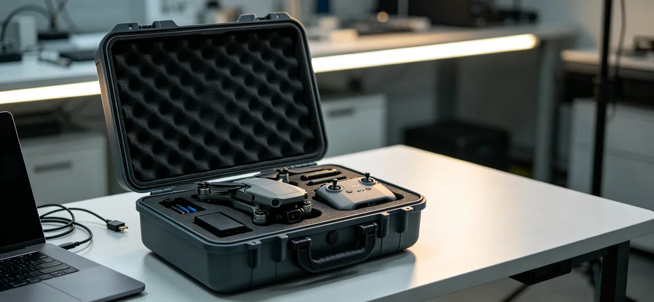
For loading methods and hold times, see the stack-load test procedure.
13. Marking, Procurement Lists and the Compliance Boundary
Clear marking tells handlers the weight, the centre of gravity and the required orientation before they touch the case, which reduces damage and accidents caused by wrong lifting or by turning a case upside down. For offshore equipment, marking should also carry the container's own maintenance history, such as gasket replacement records and the most recent test result, so that condition can be tracked over a long service life. That information is particularly valuable on vessels where cases are rotated frequently between duties.
When procuring, it is wise to write the requirement list line by line: material grade, surface treatment, hardware material, seal material and acceptance criteria. A specification that says only corrosion-resistant is difficult to verify at goods-in inspection and tends to create arguments during later maintenance. Marking should also be checked against the regulations that apply along the transport route, especially where goods cross borders and both pictograms and text must be accurate; the transport marking reference collects the relevant labelling requirements. Acceptance should include sampling and a point-by-point comparison of the delivered article with the specification, with findings fed back to the supplier to close the loop, and a register of service life, repairs and replacements is worth keeping for cases already in use. A case that is easy to identify and easy to document is also easier to withdraw from service at the right moment, which is before a failure rather than after one.
One boundary should be stated plainly here. This article discusses only the structure, materials and protective design of the container itself. It does not address the nature, properties or intended use of any packaged item, and it is not a statement about any such content. Where cross-border movement or export is involved, the responsible party must carry out its own assessment under the laws and export-control rules that apply in its jurisdiction and remains accountable for the outcome. Nothing written here is a compliance conclusion of any kind.
Frequently Asked Questions
Q: Which parts of a marine engineering protective case corrode first? A: Owners tend to watch the outer surfaces, but screw holes, handle bosses, hinge bushes and the base of a gasket groove usually fail first. Salt and moisture collect in those places, they are hard to wipe clean, and they sit in a wet-dry cycle that produces classic crevice corrosion. Inspection with a torch and a magnifier should look for rust spots and blistered coating at these locations, and any finding should be cleaned and recoated promptly so that attack does not spread into the shell. Where possible, filling these gaps with a corrosion-inhibiting sealant during assembly removes the pocket where liquid would otherwise stand. Photographing each case when it first enters service makes later changes obvious, and treating a small rust stain early is far cheaper than replacing a corroded boss or a seized hinge. Any coating repair should use a product compatible with the original system, since incompatible paints can simply hide the problem while attack continues underneath them.
Q: Can an aluminium case replace a stainless one offshore? A: It depends on the location and how often the case is handled, so a blanket answer would be misleading. Aluminium is light and easy to carry, but its oxide film is not stable in chloride conditions and needs anodising or a coating to survive; once that layer is chipped at a corner, corrosion moves inward from the damaged point. Stainless steel resists chloride better overall but is heavier and more expensive. A practical approach is to use a more corrosion-resistant material for load-bearing and permanently exposed parts, keep aluminium for weight-sensitive and easily maintained parts, and insulate the two wherever they meet. Whichever approach is taken, the interface between the two materials is the detail that decides service life, so it should be drawn and inspected rather than left to assembly practice. Trialling a single case before placing a full order usually exposes interface problems at very little cost, and it makes the final specification easier to write because the trial shows which details actually matter.
Q: How should the replacement interval for a gasket be decided? A: There is no universal number of years, because the answer depends on material, service environment and inspection findings. Ethylene-propylene-diene rubber and silicone age slowly under ultraviolet light, but they still harden under heat, ozone and frequent opening, and a hardened gasket can look intact while no longer providing real rebound. Each time a case is opened, check whether the gasket has lost elasticity or shows permanent compression marks and fine cracks, then combine that with any interval the manufacturer recommends. If water has entered, inspect the groove as well rather than replacing only the gasket and ignoring its deformed channel. It also helps to note how often a case is opened each month, because a seal used daily ages quite differently from one opened twice a year, and the maintenance plan should follow that real duty rather than a generic figure copied from a catalogue. Where several identical cases are in service, rotating them spreads wear more evenly across the fleet.
Q: Why does condensation appear inside a case with an intact exterior? A: The cause is usually the interaction between temperature change and the venting arrangement. As a case warms by day and cools at night, the air inside contracts and creates a slight negative pressure, so humid outside air is drawn in through the pressure-equalisation valve or tiny gaps and then condenses on the cooler inner wall, building up over time. Equipment itself can also carry moisture in, particularly if assembly happens during a wet season. Useful measures include matching valve airflow to the volume, controlling ambient humidity during assembly, and adding a rechargeable desiccant to the liner instead of sealing the case more tightly. A simple field check is to open the case after a cold night and look for droplets on the inner surfaces and on the underside of the lid, since that pattern points to condensation rather than to water passing a failed seal. Recording when and where dampness appears helps separate the two causes and points to the right correction.
Q: What ingress rating does an offshore case actually need? A: The duty should decide the rating, and simply chasing the highest number is rarely the best use of budget. On deck the main threat is splash and wash-down, so what matters most is whether the second digit covers spray and short-term immersion; if a case may fall into water or live in a permanently damp space, continuous immersion and condensation have to be considered as well. The first digit still matters for keeping dust and salt out of hardware. Remember that a rating is a laboratory result, and assembly quality or gasket condition can reduce field performance, so testing and scheduled inspection remain necessary. It is also worth deciding whether the case must only keep water out or must also let equipment breathe, because those two requirements pull in opposite directions and the design has to settle the priority first. A short written statement of the actual duty is a better basis for selection than a single preferred number.
Q: Can liner material be reused after it has become damp? A: It depends on the material and how wet it has become. Open-cell foam absorbs water, gains weight and loses cushioning performance, and it can hold moisture against the equipment long enough to encourage corrosion or mould, so replacement is usually the sensible option. Closed-cell foam and liners with a moisture barrier are affected much less, but they should still be dried and checked for normal resilience before reuse, because repeated wetting can change the internal structure of the material. Where the choice is open, closed-cell material plus a replaceable desiccant keeps moisture out of the cushioning layer in the first place. Because liner material costs far less than the equipment it protects, replacing doubtful foam is almost always the cheaper decision. Keeping a small stock of the correct grade also removes the temptation to reuse material that has already taken on water, and if there is any doubt at all it is best to treat the foam as a consumable rather than a permanent part of the case.
Q: Is it acceptable to lift a case by its handle? A: Usually it is not advisable. Handles are designed for short manual carrying loads, not for the concentrated pull and swinging motion that occurs during lifting. Using a handle as a lifting point often leads to local cracking or even the handle pulling away entirely. Lifting should use purpose-designed eyes or a designated lifting structure, and the case should state which points may be used and what load they carry. If a sling lift is genuinely necessary at sea, check the eye specification and the loaded weight beforehand, inspect the connection for looseness or corrosion before lifting, and slow the lift to reduce sway and shock. A sensible rule is that a case should identify its own lifting points, and if it does not, a temporary arrangement should be agreed and written down before the lift rather than improvised on a moving deck. Whoever directs the lift should also confirm that the load is balanced and that loose items inside cannot shift and change the centre of gravity in mid-air.
Q: Do salt-fog results predict service life in a real marine environment? A: Not directly. A salt-fog test accelerates attack using a concentrated sodium chloride mist at controlled temperature, which makes it convenient for comparing the relative resistance of different designs within a short period, but real offshore conditions also include ultraviolet radiation, wet-dry cycling, mechanical wear and temperature variation, and the interaction of those factors is hard to reproduce fully. The results are therefore better suited to screening options and confirming process consistency than to converting into a number of years in service. The safer approach combines laboratory findings with tracking data from vessels, recording how corrosion develops and adjusting maintenance intervals accordingly. Testing is most valuable when it is repeated on production samples over time, because a result that holds for one batch may not hold for the next, and only repeated testing shows whether a process is drifting. Used that way, salt fog becomes a tool for controlling quality as much as for predicting endurance.