

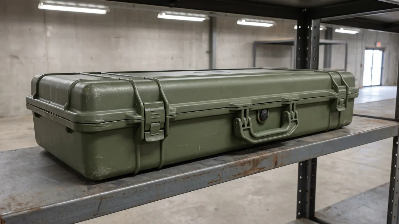
The drop test for protective cases is one of the most fundamental and most intuitive structural checks in a transport packaging verification program. It quantifies the integrity and protection retention of a container under transient impact by releasing the case from a set height in a defined attitude onto a rigid surface. For cases that travel by vehicle, vessel, aircraft, or on foot in the field, mishandling during loading, sliding from shelving, and tumbling during last-mile delivery can hardly be eliminated, so the drop test is often regarded as the most realistic destructive test of all. This article discusses only the structural verification of the protective case container itself under drop impact, focusing on the cooperative behavior of the Case Shell: Structural Materials and Molding Process of Protective Cases and the Case Seal Strip: The Key Waterproof and Dustproof Accessory for Protective Cases, so that readers can build a complete picture from specimen preparation and attitude design to acceptance criteria writing. A passing drop result describes the impact resistance of the container, not the safety level of the packed goods, and users should still judge the overall protection scheme on their own.
Position of the Drop Test in the Case Quality System
The drop test sits at the entry point of structural verification in the quality system of a protective case, and together with vibration, stacking compression, immersion, and salt spray it forms a complete sequence of transport environment simulation. Manufacturers typically schedule drop testing at three stages: design validation, pre-production confirmation, and outgoing inspection, so that the stability of tooling, material, and assembly processes can be monitored. Unlike the sustained compression examined by the Case Stacking Corner: Load-Bearing and Alignment Hardware for Stacked Cases, the drop test focuses on energy absorption and stress spreading within a transient impact that lasts only milliseconds, examining whether the case avoids through-cracks and functional failure under extremely short loading.
The drop test earns its place as a mandatory type test because it can repeatedly reproduce accidental field events in the laboratory, and because height, attitude, and impact surface are all controllable, giving it the twin advantages of being quantifiable and traceable. Once drop data enters a batch record, any future customer complaint can be quickly attributed either to insufficient design margin or to manufacturing variation, a diagnostic value that few other environmental tests can provide. It must be emphasized that a passing drop result only means the container remained intact under the given condition; it cannot be extrapolated into absolute safety under arbitrary conditions. From an economic standpoint, the drop test is destructive, and a specimen that has experienced multiple impact attitudes is usually no longer deliverable as a qualified unit, so a manufacturer must trade off sample size against representativeness, often covering the key attitudes with a small number of specimens while extracting maximum diagnostic information from accelerometers and high-speed imagery. Equally important, the drop test should not be treated as an isolated event but as one node in a chain that later compares lab damage against field returns, so that the severity levels chosen today can be recalibrated by the failure statistics of tomorrow. A recurring complaint about a cracked corner, for instance, is far more persuasive evidence for raising severity than any assumption made at the drawing board.
Applicable Standards and Reference Basis
The standards available for a protective case drop test are rather diverse. Common references include the ISTA series for international transport safety, generic GB/T and ISO packaging methods, and military or industry specifications for particular sectors. Standards differ in drop height, the number of attitudes, and acceptance criteria, yet their underlying idea is the same: simulate unavoidable accidental impact in the distribution chain with a controllable free fall. When choosing a basis, the test should first match the transport chain the product actually experiences, because the severity levels for air, rail, and road intermodal differ considerably. In line with the integration logic of the ISTA Test: Transport Test Procedure for Protective Cases, the drop is often the opening impact item of a combined sequence, followed by vibration and temperature-humidity cycling.
The choice of standard should also consider customer contracts and destination regulatory requirements, applying the strictest where necessary. When one product serves several markets, a difference list of the relevant national standards should be compiled so that a single test program does not leave gaps. It should be noted that the methods discussed here serve container structural verification only; whether the conclusion can support cross-border transport compliance must be assessed separately by the responsible party in light of export control requirements, and this article offers no compliance conclusion. Internal company standards often add finer acceptance rules on top of generic specifications, for example defining the first crack as failure or exempting non-structural cosmetic damage, and such rules should be fixed during the design review stage to avoid later disputes. Standards are also revised over time, so purchasers and suppliers should lock the year and edition of the adopted standard in the technical agreement and agree on a re-confirmation process when the edition changes, preventing a drifting basis from producing contradictory conclusions for the same design across batches. Whenever a new market or a new customer is added, the existing program should be reviewed once more against that market's expectations, because a chain that satisfies a domestic distributor may still fall short of an intermodal freight operator.
Specimen Preparation and Initial Condition
Samples must be fully preconditioned and their state confirmed before testing, which is the first gate for valid drop data. It must first be made clear whether the specimen is an empty case or one assembled with standard lining, because the presence of lining significantly changes overall stiffness and center-of-gravity distribution. The shell material, wall thickness, latch model, and seal strip batch should then be recorded, and the appearance photographed and archived with any pre-existing scratches or flash marked so that they are not confused with post-drop damage. Temperature and humidity conditioning is equally important, since plastics and alloys show clearly different impact toughness at different moisture levels and usually need enough time to equilibrate in a standard environment. In coordination with the assembly confirmation of the Case Foam Lining: Cushioning and Customization of Case Interiors, the liner should sit flush against the case and show no looseness.
The number of specimens is generally not less than the specified count so that rotation across drop attitudes can be covered. Once preconditioning is complete, a drop sequence number and observation datum lines should be marked on the specimen surface to make damage evolution easy to compare step by step. If specimens come from different mold cavities in the same batch, they should be recorded by cavity so that mold-level scatter can be detected. During state confirmation, the completeness of accessories should also be checked, for example whether the torque of handles, casters, buckles, and pressure equalization valves matches the drawing, because a missing or loose accessory changes the local load distribution at impact and pushes the conclusion away from the real product. For lined cases, the grooves and internal fixation of the liner must be checked for tightness so it cannot work loose during the drop and disturb the reading, and the liner should also be confirmed not to have absorbed moisture and softened. A photographic record of the initial state, taken from the same angles each time, makes later comparison far more reliable.
Drop Height and Impact Surface Determination
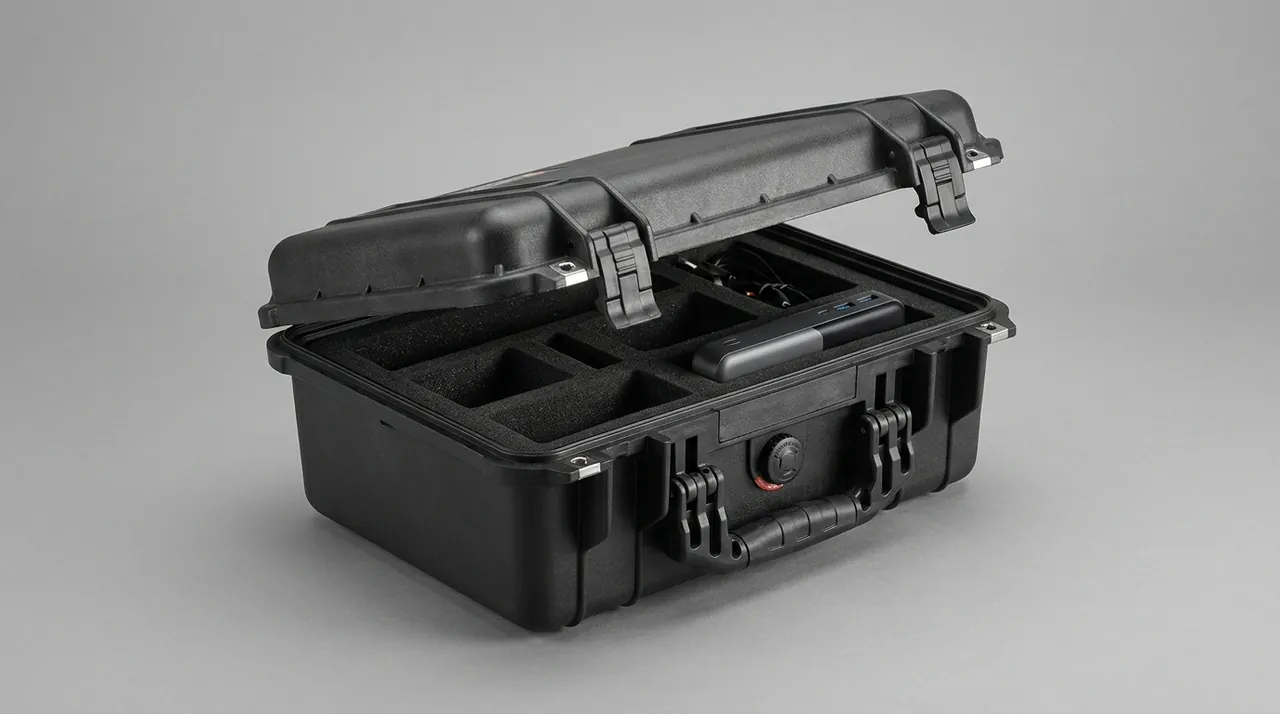
Drop height is the core parameter of test severity and is usually set by a specimen mass classification, in which a heavier sample is allowed a lower drop height to reflect the reality that a heavy object is harder to lift and drop. Beyond mass classification, height may also be set from distribution risk: a small parcel in last-mile delivery is more likely to fall from a trolley or shoulder height, while a warehouse item may fall from a pallet or rack. The impact surface is the rigid ground the sample strikes, and standards require a flat, hard surface with little elasticity, such as concrete or steel plate, so that maximum impact is transmitted. Echoing the handling directions indicated in Transport Marking: Marking Requirements for Protective Case Packaging, the drop attitudes should cover the vulnerable orientations defined by the marking as far as possible.
For models with casters or handles, the landing order of these protruding structures must be assessed separately. A higher drop height is not automatically better; excessive severity departs from the real scene and misleads the reader, so the sound approach is to determine a representative value from historical damage data and transport audits. When the transport chain includes both manual and mechanical handling, corresponding heights should be set and verified item by item rather than replacing all risk with a single maximum. The stiffness and flatness of the impact surface should also be recorded, because a wooden or elastic floor absorbs a significant amount of impact energy and lowers the severity at the same nominal height; if floor conditions differ between laboratories, results become incomparable. For larger cases, it should further be confirmed that the release mechanism does not introduce rotation at detachment, since any initial angular velocity changes the actual landing location and can degrade a planned corner drop into an edge drop, weakening the purpose of the test. Height and surface, once fixed, are best written into the plan document so that repeat testing on different dates by different operators remains comparable.
Drop Attitudes and the Order of Edge and Corner Impacts
A complete drop program requires the specimen to strike the ground in several attitudes in sequence, typically the bottom face, top face, one side face, one end face, and a number of edges and corners. The corner drop is often the most severe, because impact energy concentrates in a very small contact area and easily initiates cracks near the root of a latch or around a hinge. The edge drop tests the continuity of stiffening ribs and corner structures, and is a good opportunity to verify the load-transfer effect of the Case Stacking Corner: Load-Bearing and Alignment Hardware for Stacked Cases.
After each attitude the test should be paused to inspect and record damage before moving to the next, so that cumulative damage does not mask the failure signature of a single attitude. The attitude order is generally arranged by risk priority, placing the corner or edge most likely to expose a defect first so that design weaknesses surface early. For asymmetric cases, additional landing attitudes in the direction of center-of-gravity offset should be included. Through systematic rotation, the drop test can portray the weak orientations of a case in real tumbling fairly comprehensively and provide a clear target for structural improvement, which is more scientific than a single free fall. When the same damage appears repeatedly in one attitude, that attitude should be listed as a priority object for design change. It is worth noting that more attitudes are not always better, because an excessive count raises specimen and labor cost sharply without necessarily yielding new failure information, so engineering practice usually narrows the high-risk attitude set first through finite element analysis and historical data, then covers the key items with physical tests. Whatever the final list, it should be fixed in writing before the run begins and executed in a randomized order, so that an operator's expectation about a certain attitude cannot bias the way the result is recorded. Documenting the list also makes the program auditable, so that a customer or a certification body can see exactly which attitudes were covered and why.
Shell Material and Molding Effect on Impact Resistance
Shell material directly sets the impact ceiling and the energy dissipation mode of a case. Engineering plastics such as modified polypropylene or ABS can absorb energy through local yielding and show a ductile failure mode, while aluminum alloy shells provide excellent dent resistance through high stiffness but may crack under local overload. Injection-molded shells require attention to wall-thickness uniformity and rib layout so that thin-wall regions do not perforate in a corner drop. In agreement with the design principles of the Case Shell: Structural Materials and Molding Process of Protective Cases, a generous fillet transition lowers stress concentration, whereas too many sharp corners easily become crack initiation points.
Composite cases must also be examined for the bond between skin and core, since delamination under drop impact is also a structural failure. Material selection should balance mass, cost, and temperature-range adaptability; some plastics become brittle at low temperature, so a drop test must be added at the relevant temperature to expose cold-brittle risk. In short, a thicker shell is not automatically better; the goal is to reach the target impact protection level within a limited mass through the cooperation of material, structure, and process. The proportion of regrind should also be limited to avoid batch-to-batch impact performance drift. The wall-thickness difference between rotational molding and injection molding likewise warrants separate evaluation, because a rotomolded part often has thicker corners and thinner flat areas, which may produce a different failure sequence from an injection-molded part under the same drop. The cold-brittle transition temperature of the chosen material should also be verified at the design stage, because a case that passes at room temperature cannot automatically be assumed to survive a winter deployment or a cold-chain trip. Where a design mixes metal inserts with a polymer body, the difference in thermal expansion between the two should be considered as well, since a cold drop can load the insert bond in a way a warm drop never will. Keeping a small material database of impact results by temperature helps a designer pick a grade without repeating the same experiment on every new project.
Energy Absorption of the Interior Cushioning System
The lining is the first flexible barrier that absorbs drop impact energy, and its performance directly affects the impact level experienced by the protected object. Common foams include EVA, PE, and polyurethane, and liners of different density and closed-cell ratio differ markedly in the energy-absorption curve over the compression range. The design should let the liner fit closely around the contents so that impact load passes through broad-area compression of the liner rather than through local hard points. In coordination with the selection method of the Case Foam Lining: Cushioning and Customization of Case Interiors, the drop test can verify in reverse whether the liner compression stroke is sufficient; if the case bottom already touches the contents, the liner is too thin.
Multi-layer liners can absorb energy in layers at different impact levels, improving adaptability to a range of drop heights. The permanent deformation of the liner after repeated drops also deserves attention, because fatigue reduces the protection margin, and durable products should therefore undergo multi-round drop evaluation. It should be remembered that a liner can reduce impact but cannot compensate for a structural defect of the shell; the two must be designed together, and merely thickening foam to hide a weak case is not advisable. The liner groove shape should also match the outer contour of the contents to avoid point contact and local overload. For a compartmented liner, the partition should be assessed for whether it shifts under impact and lets items in adjacent compartments collide, and the rebound rate of the liner matters as well, since too fast a rebound produces a secondary bounce that subjects the contents to repeated loading. Measuring liner thickness before and after the drop gives a simple way to quantify how much compression recovery the cushioning actually retains. That recovered thickness is a useful acceptance parameter, because a liner that has lost most of its original height can no longer be counted on for its rated protection margin.
Latch, Hinge, and Seal Strip Condition After Drop
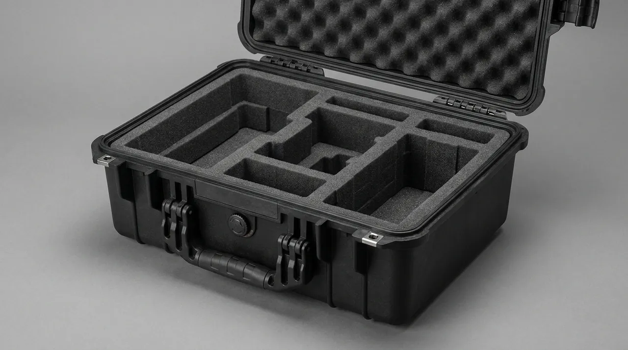
Drop impact tests not only the rigid structure but also disturbs the sealing and latching system, so the condition retention after drop is an important criterion. The seal strip may be momentarily displaced when a corner or edge lands under compression, and if the latch does not spring back in time a water path can form. In line with the compression and rebound indicators of the Case Seal Strip: The Key Waterproof and Dustproof Accessory for Protective Cases, a water-tightness check is often coupled after the drop test to confirm that the seal strip recovers its sealing under impact disturbance.
As a moving part, the latch has its root as a concentration zone of drop stress and should be checked after every attitude for looseness or plastic deformation. The hinge carries the connection stiffness between lid and body, and any clearance in its pin or bushing will amplify displacement under subsequent impact. For models with a pressure equalization valve, it should be confirmed that the valve was not jammed by foreign matter at the moment of landing. Sealing retention cannot be judged from appearance alone; where necessary, a negative-pressure or immersion test should quantify leakage, because the unaided eye cannot resolve the effect of a micron-scale gap on sealing. When latches are too few or unevenly distributed, the problem of insufficient compression at the far seal strip is further amplified after a corner drop, so the multi-latch layout and latch stiffness should be checked together in the design review. The material pairing of hinge and latch also affects service life, since dissimilar metals in long contact can accelerate wear through galvanic corrosion, especially in coastal or high-humidity use, so mating surfaces may need a protective treatment or compatible materials. The closure force of each latch should also be verified after the drop, because a latch that still closes but no longer holds its rated force may let the seal strip relax during the next impact. A simple force gauge reading taken before and after the drop is usually enough to catch this subtle degradation.
Stacking Corners and Structural Load Path Analysis
The load a case bears during a drop is not distributed evenly but spreads through a load path formed by the shell, stiffening ribs, and corner hardware. As a key load-bearing node, the stacking corner has its connection reliability directly determining whether the case keeps its shape in a corner drop. In agreement with the compression design of the Case Stacking Corner: Load-Bearing and Alignment Hardware for Stacked Cases, the drop test can verify the shear and pull-out resistance of this node under dynamic impact, covering the transient effect that static compression cannot.
Load path analysis usually employs strain gauges or high-speed imaging to observe the propagation and reflection of the impact wave on the shell and to locate energy retention zones. If cracks recur in one area, it often means the area lacks an effective stiffness transition or has a material discontinuity. By comparing damage across multiple drop attitudes, a weak-orientation map of the case can be drawn to guide rib densification or corner thickening. For large cases, the cantilever effect of handles and hinges should also be considered, because they introduce an additional bending moment at the moment of landing and are an unignorable disturbance in the load path. The bond strength between metal inserts and the plastic body should also receive dedicated attention in a corner drop, since insert pull-out directly breaks the local load path. Optimizing the load path is often not a matter of simply adding material but of lengthening the path, adding transition fillets, and placing ribs sensibly so that impact energy is absorbed and spread over a larger volume. A weak-orientation map built in this way can later be reused for other models in the same family, which shortens development and keeps the family's structural logic consistent. Documenting the insert pull-out load alongside the crack location gives designers a concrete number to improve, rather than a vague instruction to make the corner stronger. Comparing that number against the same measurement on a competitor sample also gives an honest picture of where the design stands.
Observation Records and Failure Criteria
Sound observation records are the source of the drop test's value, and merely looking for a break with the naked eye is far from enough. It is recommended to shoot high-speed video of each attitude, recording the contact point and rebound process at the moment of landing, backed by impact accelerometers that quantify peak value and duration. Consistent with the quantitative logic of IP Rating: Decoding Ingress Protection Grades for Protective Cases, drop criteria should be as measurable as possible rather than subjective. Failure criteria usually include a through-crack in the shell, loss of latch closing capability, permanent dislodging of the seal strip, structural collapse of the liner, and obvious functional deformation.
Damage that is only cosmetic and does not affect protection should be classified separately to avoid excessive rejection. The record form should include attitude number, drop height, landing location, peak acceleration, and damage description, forming a traceable archive. When several specimens show the same failure mode, a design problem can basically be pinpointed; if failures scatter randomly, process variation is more likely and the search should shift to the manufacturing process, a distinction that is decisive for the direction of improvement. It is advisable to establish a correspondence between acceleration peaks and damage grades to form a quantitative curve that can serve as input for later design work rather than a one-off conclusion. The criteria should further separate repairable from non-repairable damage: a repairable item should be recorded but not rejected outright, while a non-repairable item such as permanent deformation of the sealing interface or loss of latch function should be treated as a veto item. Recording peak acceleration alongside a short description of the damage allows later engineers to compare the energy a case actually absorbed, not merely whether it happened to break that day. Where the failure mode is consistent across specimens, the report should say so explicitly, because that is the strongest single signal that the root cause lies in the design rather than in chance.
Post-Drop Function Checks and Immersion Coupling
After a single drop is complete, a function check should be performed without disassembly to confirm that latches open and close normally, that the handle makes no abnormal noise, and that casters turn freely, before deciding whether to proceed to the next attitude or to a special inspection. To verify the true sealing performance after impact, a dropped specimen is often moved to the Water Immersion Test: Quantitative Sealing Verification for Protective Cases for immersion or spray so that any seal strip displacement can be observed as ingress. This sequencing is closer to real distribution, in which a case often experiences a handling drop first and is then stored or transported in a damp environment.
The function check should also include measurement of the lid fit gap, because minor deformation after a drop can open a gap at the mating surface that, although not a crack, already impairs protection. For models with instruments or a vent valve, these accessories should be confirmed to work after impact, and an airtightness check should be added where necessary. When the drop test is combined with the Vibration Test: Random Vibration Verification for Protective Cases, vibration fatigue can be applied first and the drop performed afterward, which more fully exposes weak points caused by loosened fasteners. It should be noted that this article discusses only the structural performance of the container during the drop and the subsequent immersion check, without touching the performance or state of any packed goods, and the resulting data serve structural improvement reference only. Turning the check into a scored sheet covering opening smoothness, fit gap, and accessory function keeps the operator's judgment consistent and gives different batches a common yardstick. A simple score, agreed in advance, turns a subjective impression of stiffness into a number that can be tracked over the product's life and compared between suppliers. A sudden drop in the score is often the first visible sign of a process change that has not yet caused a functional failure.
Drop Severity Across Typical Industries
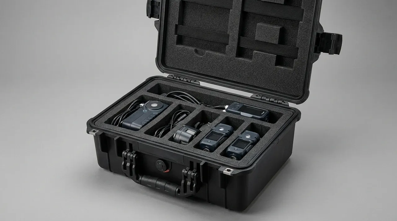
The transport chain of each industry produces markedly different drop severity, so the test setup should fit the real situation instead of applying one uniform height. Mining cases and Mining Case: Protective Cases for Mining Equipment are often shoulder-carried and slid down on rugged sites with higher height and frequency, so corner and edge tolerance matters more. Power Utility Case: Protective Cases for Power Utility Equipment in inspection work are mostly transferred between towers and vehicle beds, emphasizing side and handle cantilever impact. Petrochemical Case: Protective Cases for Petrochemical Equipment must balance a corrosive environment with drop, so salt spray is often combined with drop evaluation.
Rail Transit Case: Protective Cases for Rail Transit Equipment experience regular vibration overlaid with occasional handling drops, while Marine Engineering Case: Protective Cases for Marine Engineering Equipment emphasize sealing retention after humidity and salt spray. Cold Chain Case: Protective Cases for Cold Chain Logistics face cold-brittle risk because materials become fragile at low temperature. Airport Ground Case: Protective Cases for Airport Ground Support focus on tumbling drops during baggage-style transfer, Water Conservancy Case: Protective Cases for Hydrology and Water Conservancy Monitoring care about handling impact on damp sites, and Border Patrol Case: Protective Cases for Border Patrol Equipment stress cumulative damage from repeated small drops during field carry. Tailoring severity to the real scene is what gives the verification engineering meaning, and it also makes it easier to explain the origin of every parameter when communicating with customers. For a case intended to serve several industries, a common baseline drawn from the strictest typical scenario can be combined with customer-specific variations to balance universality against specificity. The draft sequence should still be reviewed by the customer's technical contact, because only they can confirm that the chosen severity reflects the journeys their product will really make. Where opinion differs, a short pilot test on a representative sample is usually cheaper than arguing the point on paper.
Test Report Writing, Compliance Notes, and Certification
A complete drop test report should include specimen information, the referenced standard, the drop matrix, observation data, damage photos, and conclusions and recommendations, so that any third party can reproduce it. The report must state whether each attitude passed and give an overall judgment and improvement items, attaching high-speed video and acceleration curves as supporting evidence where necessary. In line with the submission requirements of UN Certification: Transport Safety Certification for Protective Cases and AAR Certification: Admission Requirements for Rail Intermodal Packaging, drop data often serve as key supporting material for the transport safety argument, and its format and traceability directly affect certification efficiency.
The writing should further distinguish design validation from batch consistency sampling, the former for type approval and the latter for outgoing control, and the report should end with follow-up actions such as thickening the corner wall, optimizing the latch root fillet, or adjusting the liner density. It must be stated specifically that this article discusses only the verification method of the protective case container structure under drop impact and does not involve the nature or state of any packed goods; cross-border transport and export of related products must follow local laws, regulations, and export control requirements, with compliance assessed separately by the responsible party. Nothing here constitutes a compliance conclusion, nor a commitment regarding the suitability of any particular mode of transport. The report should also note the test environment, equipment traceability information, and operator so as to satisfy the evidence-chain completeness expected by technical compliance review, and a trend table of key indicators across successive reports can turn drop testing from a one-off acceptance step into an ongoing quality monitoring tool, letting a batch whose consistency drifts from history be intercepted before shipment. Over time, this running record also becomes a strong internal benchmark for judging whether a proposed cost reduction would quietly erode the case's impact performance. In that sense, the archive of drop reports is as much a design tool as the accelerometers and cameras used on the day of the test.
Frequently Asked Questions
Q: How should the drop height be determined so that it is reasonable? A: Drop height is usually set by a specimen mass classification, in which a heavier sample is allowed a lower height, and it may also be based on the risk of the actual transport stage, for example a last-mile parcel falling from a trolley or shoulder height while a warehouse item falls from a pallet or rack. A reasonable height comes from historical damage data and transport audits, being both challenging and explainable rather than simply as high as possible. It is advisable to first match the transport chain the product really experiences and to reference the corresponding level in ISTA or an industry specification, applying the strictest requirement where necessary so that the result guides structural improvement. When the chain includes both manual and mechanical handling, the heights should be set and verified item by item instead of letting a single maximum hide a locally high-risk stage, which is what makes the test genuinely serve product quality and structural optimization.
Q: Why do empty-case and lined-case drops give clearly different results? A: The presence of lining significantly changes the overall stiffness, mass distribution, and center of gravity of a case, and therefore changes the landing attitude and the path along which impact energy is transferred. With standard lining in place, the foam compresses first and absorbs energy, lowering the impact level on the shell and the contents; an empty case lacks this flexible cushion, so the shell takes the impact directly and is more likely to crack at a corner or edge. The specimen state must therefore be made clear before testing and kept consistent with the lining assembly specification, otherwise the conclusion cannot represent real use and has no cross-comparability. If a product might be shipped both empty and fully loaded, it is advisable to drop in both states to cover the worst combination, giving a more complete basis for design margin assessment and avoiding the misjudgment risk that a single-state conclusion can introduce.
Q: Why is the corner drop often the most severe attitude? A: In a corner drop the impact energy concentrates in a very small contact area, and the local stress far exceeds the uniform distribution seen when the bottom or side lands flat, so cracking is easily initiated at a latch root, near a hinge, or at a corner reinforcement. Because the contact area is small and the contact time short, the peak acceleration is usually higher, making it a severe test of material toughness and structural continuity. For this reason standard programs treat the corner attitude as a focus and recommend placing the corner most likely to expose a defect first, so that design weaknesses surface early and can guide rib or fillet optimization. When the same crack recurs at one corner, that corner should be listed as the priority object of a design change, dispersing impact energy by thickening the corner wall or improving the insert layout, turning the most severe attitude into useful diagnostic information rather than a mere pass threshold.
Q: After a drop, how is it judged whether the sealing system is still effective? A: It cannot be judged only by whether there is a visible crack, because momentary displacement of the seal strip or incomplete latch rebound can also form a water path. The standard practice is to couple a water-tightness check after the drop, such as immersion or spray with quantified leakage, while checking whether the seal strip has come out of its groove and whether the latch has lost closing capability. Models with a pressure equalization valve must also be confirmed not to have a jammed valve. This article discusses only the state of container sealing after impact and does not involve the protection grade of packed goods; related sealing and cross-border transport requirements should be confirmed by the responsible party. To make the criterion more objective, a quantitative scoring sheet recording seal strip rebound, latch closing force, and measured leak rate is recommended, turning sealing retention from a subjective visual check into traceable data for batch comparison.
Q: For impact resistance, is plastic or aluminum alloy the better shell material? A: The two behave by different mechanisms. Modified polypropylene or ABS can absorb energy through local yielding during impact, showing ductile failure, while aluminum alloy resists denting well through high stiffness but may crack under local overload. Injection-molded shells need attention to wall-thickness uniformity and rib layout to avoid perforation in thin areas, and composite cases must also be watched for delamination. Material selection should balance mass, cost, and temperature-range adaptability, and since some plastics become brittle at low temperature, a cold drop test must be added. Thicker is not always better; the aim is a coordinated material, structure, and process that reaches the target protection level. The proportion of regrind should also be limited to avoid batch-to-batch drift, and rib space should be reserved at the mold design stage so that the shell gains enough drop margin within a limited mass, which is the sound and reproducible engineering trade-off. Running a plastic and an alloy sample side by side through the same attitude matrix usually settles the material choice faster than any purely theoretical comparison can.
Q: Can a thicker lining replace structural improvement of the shell? A: No. Although a liner can lower the transmitted impact level, it cannot compensate for a structural defect of the shell, such as an insufficient corner wall or stress concentration at the latch root, and merely thickening the foam hides the problem instead of solving it. The correct approach is to design the liner and the shell together: the liner provides flexible energy absorption and locating fit, while the shell provides overall stiffness and resistance to penetration. The drop test should evaluate both, since a case bottom that touches the contents means the liner is too thin, while a cracked shell means the structure needs strengthening, and the two improvement directions cannot substitute for each other. The liner groove shape should also match the outer contour of the contents to avoid point contact and local overload; only by coordinating the two can the expected transport protection target be met within a limited mass, and single-point optimization cannot cover a system shortfall.
Q: What key contents should a drop test report include? A: The report should include specimen information, the referenced standard, the drop matrix, observation data for each attitude, damage photos, and an overall conclusion, supported by high-speed video or acceleration curves. It must distinguish design validation from batch sampling, the former for type approval and the latter for outgoing control. When interfacing with certification submissions such as UN or AAR, the traceability of the data directly affects certification efficiency. The report should end with follow-up actions such as thickening the corner, optimizing the latch fillet, or adjusting the liner density, forming a workable improvement loop. It is advisable to build a correspondence index between damage photos and acceleration curves for quick evidence retrieval during review, and to note the test environment and equipment traceability so that any third party can reproduce the result, genuinely giving the report its dual role of evidence and improvement in the quality system. Keeping one consistent reporting template across projects also lets reviewers compare results quickly and spot a design regression before it reaches the field.
Q: Can drop severity levels be shared across different industries? A: They should not be shared, because the transport chains of different industries differ markedly. On a mining site, cases are shoulder-carried and slid, with high height and frequency, so corner and edge tolerance dominates; power utility inspection mostly transfers cases between towers and vehicle beds, emphasizing side and handle cantilever impact; petrochemical work often combines salt spray with drop; cold chain faces cold-brittle risk because materials become fragile at low temperature; marine engineering stresses sealing retention after salt spray and humidity. Severity should be tailored to the real scene so that verification has engineering meaning and avoids testing that is either excessive or insufficient for the actual use, which is the first principle of test program design. Airport ground transfer focuses on baggage-style tumbling drops, water conservancy sites on handling impact in damp conditions, and geological exploration on cumulative damage from repeated small drops during off-road transport, all of which should be reflected separately in the plan.
Q: Can the drop test be used directly as a basis for product export compliance? A: No. The drop test verifies only the structural performance of the container under impact, and although its data can support a transport safety argument, whether a product can be transported cross-border or exported also involves local laws and regulations, transport marking, and export control. Nothing in this article constitutes a compliance conclusion, nor a commitment regarding the suitability of any particular mode of transport. The related compliance assessment should be completed separately by the responsible party in light of destination regulation and export control requirements, with the test report serving only as one reference input for structural improvement. The evaluation should further be combined with the Salt Spray Test: Corrosion Resistance Verification for Protective Cases and structural items such as stacking, and for products sold in several countries a difference list of national standards should be compiled, with a complete traceability and criteria statement attached at declaration time to satisfy the evidence-chain completeness expected by review.