

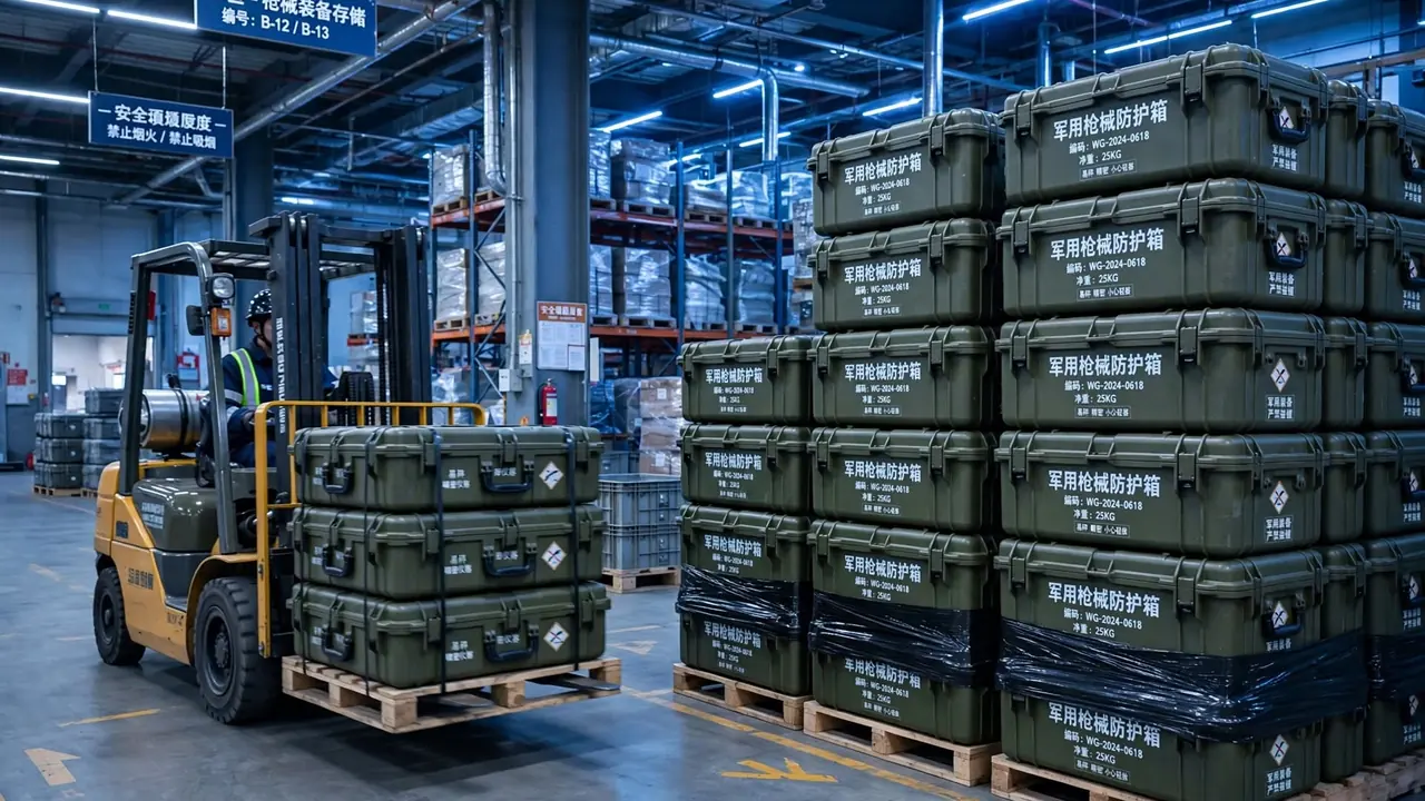
A protective case either keeps water out or it does not, and "it looks dry inside" is not evidence. Immersion testing submerges the entire sample so that three controllable quantities - hydrostatic pressure, hold time, and ingress mass - translate a vague question about leakage into a specific statement about how much water entered, under what pressure, and over how long. This guide stays strictly inside the container itself: the shell, the gasket, the groove, the latches, the vent and drain hardware, and the way they behave when the case is held underwater. We will walk through where immersion testing sits among the other structural tests, how water physically crosses a seal, how to condition and inspect the sample, how to choose depth and duration, how to build a repeatable rig, how compression and groove geometry set the sealing boundary, how shell deflection opens gaps, how to detect and quantify leaks, how immersion relates to ingress-protection grading, how valves and membranes are treated as part of the seal, and how to correct the failures the test tends to expose. The goal is to make sealing measurable long before a customer ever notices a problem.
1. Where Immersion Testing Fits in Sealing Verification
Protective cases are qualified by a chain of complementary tests. A drop test answers whether the structure survives an impact. A vibration test answers whether fasteners and interfaces stay tight through long transport. Immersion testing inverts the question: it applies a steady external water pressure first and then asks whether the seal interface can hold that pressure outside the case. It is a static but sustained check. It creates no instantaneous shock, yet over many minutes it pushes the gasket, groove, latches, and shell toward their individual limits. If the case shell design is short on stiffness or concentrates seams in one area, hydrostatic pressure magnifies those weaknesses into visible seepage.
Compared with rain or spray testing, immersion is the harsher condition. Spray tests the canopy and drainage path; water mostly runs off the surface and contact pressure stays near ambient. Immersion presses water against every point of the seal interface from all directions at once, so any under-compressed section is treated exactly like every other. That is why immersion is often used as a lower-bound check: a case that stays dry at a specified depth and duration usually has ample margin for gentler rain and splash duty. The reverse does not hold. Passing a spray test does not imply passing immersion, and this asymmetry is the root of many sealing failures in the field.
Once the role is clear, the parameters cannot be filled in casually. Depth, duration, water quality, sampling, and pass criteria must be tied to a target ingress-protection level or a customer agreement; otherwise the same case can produce contradictory verdicts in two different laboratories. The more defensible engineering approach is to identify the harshest duty the case must cover and then derive the test parameters from it, rather than running a generic soak and later claiming it covers every scenario. A useful discipline is to write the acceptance sentence before running the test: state exactly what result would cause a rejection, and confirm that the measurement can actually resolve it. If the equipment or the sample count cannot distinguish pass from fail at the chosen margin, the test is decorative rather than decisive, and no amount of careful procedure will rescue it.
2. How Water Actually Crosses a Seal Interface
To design a meaningful immersion test, start by understanding where water enters. A seal interface is not an ideal zero-gap line; it is a three-dimensional channel formed by the gasket, the groove, the clamping faces, and the shell. Water moves through it under three dominant mechanisms: differential pressure, capillarity, and thermal breathing. Differential pressure is the most intuitive - external hydrostatic pressure exceeds internal air pressure, so water is pushed toward the low side. Capillarity appears in very narrow crevices, where liquid is drawn along a groove even when the pressure difference is tiny. Thermal breathing comes from air inside a sealed cavity contracting as it cools, creating a transient negative pressure that pulls outside water or vapor across the seal line. Once gasket compression takes a permanent set, all three mechanisms grow at the same time.
Pressure-driven leakage usually shows up as steady dripping or wall wetting, and it tends to appear at gasket corners, butt joints, or near latches. Capillary leakage is far more subtle: the case may look completely dry after a short soak and only reveal a trace after the hold time is extended or detection sensitivity is raised. Thermal-breathing ingress often comes with condensation - the case is closed warm, then placed in cooler water, the trapped air contracts, and vapor or droplets are drawn in and condense on interior walls. A test that only "soaks for a while and takes a look" can miss this entire category of slow ingress.
From an engineering standpoint, this path analysis dictates which detection method you choose. For pressure-driven leaks, pressure decay or tracer gas is more sensitive. For capillary leaks, you need a long enough hold time plus dye tracing. For thermal breathing, control the temperature difference and inspect the interior for condensation. Matching mechanism to method is what prevents the awkward situation where expensive equipment still fails to catch the real defect. The value of immersion testing is precisely that it makes these paths surface together under controlled conditions, turning a sporadic field complaint into an analyzable object.
3. Conditioning the Sample and Inspecting the Build Before Immersion
The repeatability of immersion testing depends heavily on the state of the sample before it ever touches water. A gasket is a polymer part, and its storage environment, assembly age, and compression history all influence how it rebounds. A sample pulled straight from a cold store and dropped into water has a stiff, slow-rebound gasket and will show higher ingress than it should. A sample that was just over-clamped, with its shape memory not yet recovered, may look optimistic. The established practice is to rest the sample in a stable temperature and humidity environment long enough for the gasket to return to a mechanical state close to its design condition, and only then begin the test.
Assembly inspection deserves equal attention. Confirm that the gasket runs continuously around the full perimeter, with no twist or lifted edge; that corner joints carry a sensible allowance; that latches close in the intended order and torque; and that the shell parting line is clean. If the internal foam lining layout presses onto the seal line, it can nudge the gasket open by a microscopic notch when the case closes - a defect that is invisible from outside yet enough to cause intermittent seepage during immersion. When in doubt, run a low-pressure air-tightness pre-check after assembly and remove obviously non-conforming samples before they can contaminate the quantitative statistics.
Sample count and grouping also need planning. Testing a single unit cannot separate a design flaw from unit-to-unit variation, so prepare several units from the same batch and, where possible, add one known-good control. Before immersion, weigh, photograph, and record every sample, including gasket lot number and latch torque, to establish a comparable baseline. Conditioning is not a formality; it sets the credibility of every number that follows. Documentation during conditioning is as important as the conditioning itself. Record ambient temperature and humidity, resting duration, and the conditioning history of any gasket that was replaced, because these notes are what allow a later laboratory to reproduce the same starting state. A sample with an unclear history is a weak reference even if its dimensions are perfect, and it should not be used as a control. The best practice is to treat every sample as a small experiment in its own right, with a state that can be described, repeated, and challenged.
4. Choosing Depth, Hydrostatic Pressure, and Hold Time
Immersion testing rests on just three core parameters: depth, duration, and water quality. Depth sets the hydrostatic pressure. Using the liquid static-pressure relationship, each metre of fresh water adds roughly 9.8 kilopascals, or about 0.1 bar. If a target level calls for one metre for thirty minutes, the extra pressure on the case surface is about one tenth of atmospheric pressure. Raise the depth to ten metres and that value approaches a full atmosphere, changing the demands on shell stiffness and gasket compression entirely. When defining parameters, write the harshest depth and duration into the protocol instead of picking a convenient round number.
Duration is easier to underestimate. Most leakage is not instantaneous; it accumulates with soak time as the gasket creeps, crevices become wetted, and thermal breathing cycles repeat. A case whose dominant path is capillary or breathing may look fine over a short soak and only reveal ingress after several hours. The hold time should therefore cover the longest credible immersion in the target duty and still carry margin. Merely threading the needle on time tends to mean failure the moment field conditions exceed the schedule. Water quality also matters: deionised water, tap water, and saline water differ in surface tension and wetting behaviour, which changes how quickly capillary ingress proceeds. When several grades must be covered, the same tank can serve them all, but the depth and duration for each grade should be listed separately so that no tier is quietly tested at a weaker setting.
Finally, account for the loading and unloading process. Slamming the sample into the water creates a transient shock and local turbulence that can peel a gasket open; likewise, reversing the pressure direction on exit can drag water already sitting in a crevice toward the interior. The disciplined routine is a slow descent, a slow lift, and a wipe of the exterior before weighing, so that attached water is distinguished from true internal ingress. These details look trivial but directly determine whether results are comparable. To cover several grades, organise multiple depth-and-duration tiers using the classification behind the IP rating.
5. Building the Immersion Rig and Depth Reference
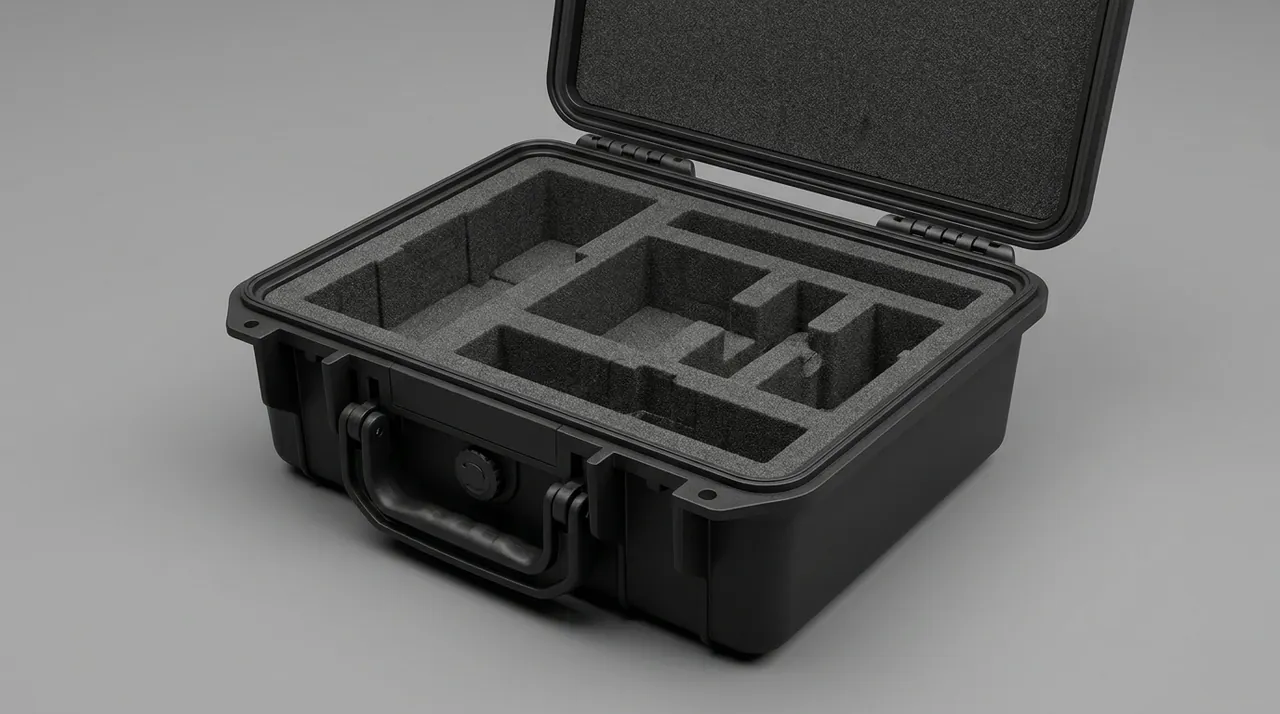
A workable immersion rig has at least four parts: a tank, a depth reference, a restraint and ballast arrangement, and temperature control. The tank must be large enough to surround the sample with water on all sides; a case pressed against the wall distorts local flow or creates dead zones. The depth reference removes the ambiguity between "water surface to the case bottom" and "water surface to the case top"; the effective depth is normally the distance from the highest seal interface to the surface. Water temperature must be recorded and kept as stable as practical, because it directly affects water density, viscosity, and gasket hardness. The restraint thinking used in a drop test setup transfers well here: soft straps or a low-stress cradle hold the sample in the required attitude so the fixture itself does not impose extra deformation on the shell.
Ballast and buoyancy form an easily overlooked conflict. An empty case is often quite buoyant and needs ballast to reach the target depth, but ballast pressing directly on the shell introduces extra stress and can even dent it locally, either helping the seal or prying it open. A sounder approach delivers ballast through a frame so the load is spread evenly, or uses an adjustable suspension in which the sample hovers stably once weight and buoyancy balance. When the opening direction matters, the portion above the surface must be kept dry, which calls for a dedicated shield or simply an opening-up attitude.
After the rig is assembled, validate it with a known-good reference unit under no load, confirming that the depth reading, temperature stability, and weighing procedure all behave, before introducing real samples. Instruments need periodic calibration, especially the depth scale and the balance; a small-range balance is critical for ingress determination. Control the uncertainty of the rig itself and the numbers become meaningful; skip this and results cannot be compared across shifts or operators. Keep a simple log for each run that captures the tank used, the reference depth, the water temperature at start and end, and any deviation from the intended procedure. Over time this log becomes the evidence that the rig itself has not drifted, which is often more valuable than any single measurement.
6. The Seal Interface: Compression, Groove, and Fill Ratio
A gasket seals through the rebound force it generates once compressed, not through the softness of its material. Too little compression means insufficient contact pressure, and water can push the gap open under differential pressure. Too much compression keeps the gasket under high stress, accelerates permanent set, and strips away rebound after a few cycles. This is a large part of why immersion testing stresses hold time: differences are invisible over short durations, but the over-compressed sample fails first over longer ones. In practice, gasket compression is held within a validated range, and the groove shape and dimensions are matched to it.
Groove design governs how the gasket is loaded. Rectangular, dovetail, and semicircular profiles differ in lateral support and compression distribution. Fill ratio is another key quantity: if the gasket cross-section is too large relative to the groove volume, it has nowhere to go when the case closes and forces the parting line apart; too small and the gasket may roll or flip inside the groove and lose a stable compression line. A sensible fill ratio lets the gasket be fully compressed during closure while retaining a sliver of deformation room, so it keeps continuous contact under water pressure. Gasket compression and the temperature effect on material hardness, as seen in a temperature-controlled enclosure, should be evaluated jointly rather than each being assigned a guessed value.
Continuity of the seal interface matters just as much. Corners, butt joints, screw holes, and cable exits are places where uniform compression is hard to maintain, and they are the first points to leak in immersion testing. Design the gasket to run the full perimeter without breaks wherever possible; when a joint is unavoidable, use a scarf or moulded splice and match its compression to the straight runs. For cases that must pass cables, use sealed glands or potting and treat the pass-through as a controlled node of the seal interface, not an opening to patch later.
7. Coupling Between Shell Deflection and Seal Clearance
During immersion, what gets compressed and stretched is not only the gasket but the shell as well. Hydrostatic pressure produces bending stress in the walls and elastic deflection in the case. If stiffness is insufficient, the inward relative displacement of the wall can exceed the gasket's ability to rebound, opening a gap exactly where the seal was previously tight. This failure is often invisible in shallow water and deteriorates quickly as depth increases. Common ways to raise stiffness include adding ribs, refining the parting-line path, and applying local thickening similar to a stacking corner guard so deflection concentrates away from the sealing zone.
Deflection and sealing are coupled: shell deformation changes the gasket's actual compression, while the gasket reaction force in turn restrains the shell. The two cannot be calculated in isolation. For large cases, pay particular attention to the mid-span of the parting line, which sits farthest from the latches, has the weakest constraint, and opens first. A practical tactic is to model the gasket as a nonlinear spring and observe the seal-interface gap under the target pressure, then compare it with the pressure the gasket can withstand at that compression.
Also account for initial deformation introduced by manufacturing and assembly. Residual stress from moulding, stacking loads in storage, and knocks in transit leave the shell with some warp before the test even starts. If the initial gap already approaches the gasket's compensation limit, then a little help from water pressure is all it takes for the seal to fail. Measuring dimensions and checking flatness before immersion is therefore worthwhile; it separates designed deflection from inherent defects and keeps the two from being confused. A practical safeguard is to test the case at the shallow depth first and step up gradually, observing whether ingress appears suddenly or grows smoothly. A sudden onset points to a stiffness threshold being crossed, which is a design signature rather than a manufacturing fluke; a smooth increase points more toward gasket creep or a marginal seal. Reading the shape of the response, not just its magnitude, tells you which corrective lever to pull.
8. A Tiered Family of Leak-Detection Methods
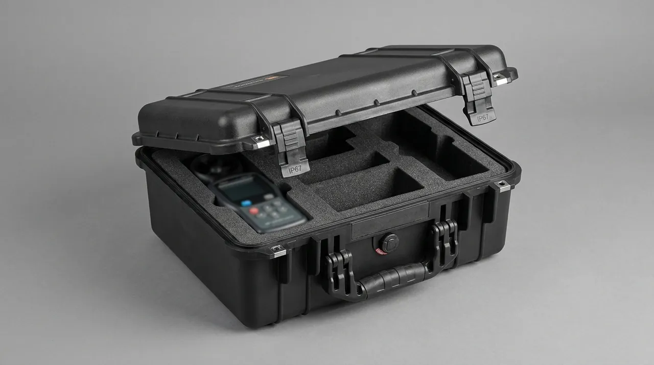
Immersion testing is not the same as "soak it and take a peek." Judging ingress requires a layered set of methods. The most basic is visual inspection: dry the exterior, open the case immediately, and look for droplets, films, or obvious wet traces on interior walls, drainage channels, and low points, with photographic records. Visual inspection is cheap and needs no equipment, but it only catches larger ingress and is insensitive to trace leaks. The second tier is gravimetric: weigh the case before and after, or place a dry desiccant pack inside and weigh its gain, using the mass difference as the ingress measure. This is the most direct quantitative approach.
The third tier is tracing: add fluorescent dye or soluble salt to the water, then search the interior with an ultraviolet lamp or conductivity probe for residual tracer. The advantage of tracing is localisation - the dye leaves a colour trail along the entry path and helps decide whether the leak is at the gasket, a valve, or the parting line. The fourth tier is pressure decay and air-tightness testing: pressurise or evacuate the case, measure the pressure change over a set interval, and convert it to an equivalent leak rate. These methods are sensitive and repeatable, but they run separately from immersion and demand care not to attribute the test equipment's own error to the case.
Method choice should match severity. If the goal is simply "keep out heavy rain," visual inspection plus weighing is usually enough. If the case is used at depth for long periods, add pressure decay or tracing to raise sensitivity. Cross-checking with several methods has an extra benefit: when results disagree, the leak path is atypical, which usually signals a hidden design or assembly issue. If the case also serves corrosive environments, sequence it with salt spray testing - first read ingress, then read post-leak corrosion behaviour. Whichever combination you choose, fix the order in the protocol and repeat it exactly; swapping methods between runs introduces differences that are easy to mistake for a change in the case itself.
9. Quantifying Ingress and Setting a Pass Threshold
Turning leakage into a number first requires defining ingress and setting a threshold. The most common quantity is mass gain: post-immersion mass minus pre-immersion mass, with attached surface water removed, approximates internal ingress. If a desiccant of known dry mass sits inside, its gain serves as a proxy for internal ingress and effectively excludes exterior carry-over. Ingress volume follows from mass divided by density, letting you estimate how much water entered and judge whether it is a few drops of condensate or a substantive leak.
Thresholds must track the application; there is no universal figure. For a case holding moisture-sensitive equipment, allowable ingress may be a few grams or even a zero-visible-water requirement; for a case used only in brief splash duty, the threshold can be looser. A common pattern is to set both a limit value and an attention value: exceeding the limit fails the unit, while landing in the attention band triggers retest or tightening. The threshold should also scale with severity - the deeper and longer the soak, the more a given ingress mass implies a serious sealing problem.
To keep data comparable, record ambient temperature, water temperature, immersion start and end times, sample attitude, and the accuracy and reading of the weighing instrument every run. An unqualified "twelve grams of water" with no metadata can neither be explained nor compared with the next lot. The point of quantitative verification is not a flattering number but a reproducible decision chain that allows different laboratories and batches to corroborate one another. When a result sits near the threshold boundary, raise confidence by increasing sample count or extending duration rather than rounding off. Where transport compliance is involved, organise the test sequence along the lines of ISTA distribution testing. It also helps to express results as both an absolute mass and a rate per hour of immersion, because a case that leaks slowly over a long soak and one that admits the same total in a short burst pose different risks in service. Reporting the rate makes the time dependence visible and prevents a single soak duration from hiding how the seal behaves when the duty changes.
10. Linking Immersion Testing to IP-Type Qualification
Immersion testing and ingress-protection testing are not two unrelated systems. The water classification within an ingress-protection scheme already includes a temporary-immersion tier and a continuous-immersion tier; the former corresponds to shallower depth and shorter time, the latter to staying dry under harsher conditions. When a manufacturer runs an immersion test, it is usually translating those clause requirements into concrete depth, duration, and pass criteria. Understanding the physics behind the clauses matters more than memorising the numbers: depth maps to pressure, duration maps to cumulative effect, and ingress criteria map to how much is considered unacceptable.
One easily missed point is that ingress-protection testing constrains dust and water together, and dust from a dust test can interact with the gasket and alter its surface. If dust particles lodge on the gasket face, they can break the contact line on closure, so a case that passed before may leak on subsequent immersion. When building the test sequence, state whether dust or water comes first, and whether a dust-then-immersion combination is required. Writing the order down prevents contradictory verdicts that arise purely from sequencing. Further detail on classification and structural admission is covered by UN packaging certification.
It is worth stressing that a grade label is a minimum promise, not a performance ceiling. A case rated to a given level is only proven under the defined test conditions; it is not guaranteed at greater depth or longer duration. Engineering selection should keep margin against the real duty and treat the grade as a starting point rather than a finish line. Where several conditions stack up, combination testing should confirm that no single capability weakens another. When a case is intended for several markets, resist the temptation to design a single test that satisfies the loosest requirement and then advertise the strictest grade. The structural work behind each tier, particularly the depth and the sealing margin, differs enough that a genuine pass at the higher tier is worth more than a nominal claim at it. Buyers increasingly ask for the raw records, and a claim that cannot be traced to a specific depth, duration, and ingress figure will not survive scrutiny.
11. Sealing Drain Valves, Breather Vents, and Vent Membranes
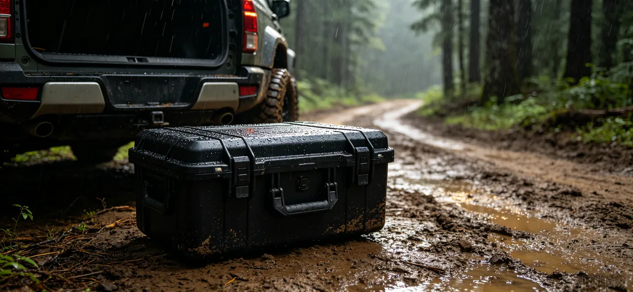
Almost every sealed case carries some interface with the outside world, most often a drain valve or a breather vent. The core job of a breather vent is to equalise the pressure difference across the wall: as the case experiences temperature or altitude changes, without a path the internal pressure difference keeps acting on the seal interface, loading the gasket and potentially drawing moisture in during cooling. A vent fitted with a hydrophobic membrane lets gas pass while blocking liquid water, keeping the seal intact while removing the pressure difference. The sealing performance of these components must be included in immersion evaluation, because they are among the weakest nodes on the whole case.
Drain valves and fill-and-drain ports test sealing after closure. A valve must form a reliable seal when shut while still draining freely when open. Immersion testing should assess both the closed-valve and slightly-weeping-valve cases, checking whether the stem, O-ring, and seat maintain contact under sustained pressure. For large cases or marine engineering cases, valves are often exposed to humid and saline conditions for long periods, and ageing of the O-ring noticeably changes its seating force, so resistance to media and ageing should be evaluated at the material level too.
Treating valve hardware as a removable node of the seal interface is the key mindset. It means the flatness of the seat, the tightening torque, and the O-ring compression all need the same explicit specification and inspection as the main gasket, rather than "just tighten it." Record the model, lot, and installation orientation of the valve, and inspect its sealing face separately after immersion. Only when the main seal and every auxiliary interface have passed does the sealing conclusion for the whole case hold. It is also worth pressure-testing the maintenance assumption: if a vent membrane or valve seal is meant to be replaced at intervals, confirm that the replacement procedure restores the same sealing performance, because a serviceable node that cannot be serviced reliably is still a leak waiting to happen.
12. Common Failure Modes and Corrective Paths
Problems exposed by immersion testing usually fall into a few typical patterns. The first is insufficient or excessive gasket compression: the former shows pressure-driven leakage, the latter permanent set after repeated cycles. Correction means recalculating the compression ratio, adjusting groove depth, or switching to a gasket of different hardness. The second is corner and butt-joint leakage, usually caused by the gasket being stretched thin at a corner or a misaligned splice; the fix lies in splice technique and corner radii. The third is parting-line opening from shell deflection, which needs ribs or local thickening to raise stiffness plus a recheck of the gap at the harshest depth. The fourth is auxiliary-interface leakage, including breather vents, drain valves, cable exits, and nameplate screws, each of which should be brought back under the sealing-node specification.
Failure analysis should avoid the habit of simply replacing the gasket. Many repeatedly leaking cases fail not because of the gasket but because of shell stiffness, assembly order, or valve selection. A systematic approach locates the leak with tracing, verifies the actual gap and compression at that location with simulation or simple measurement, and then decides whether the cause is design or manufacturing variation. Only an accurate root cause prevents recurrence. A short corrective report that links the symptom, the located leak path, and the verified fix is worth keeping, because it turns a single failure into a reusable design lesson. For power utility cases that are opened frequently under harsh field conditions, leave extra margin on latch and gasket wear and contamination resistance.
For completeness: this article discusses only the structure, sealing, and test methods of the protective case container itself. It does not address the nature, purpose, or composition of anything packed inside. If a protective case is used for cross-border transport or export, the responsible party must assess and satisfy the destination's laws, transport regulations, and applicable export-control rules on its own; the content here is a container-engineering discussion and does not constitute a compliance determination or legal opinion, and any admission conclusion must rest on the formal assessment of the competent authority and the responsible party.
Frequently Asked Questions
Q: Is immersion testing the same thing as ingress-protection testing? A: They overlap but are not identical. Ingress-protection testing is a grading system: it divides water resistance into named tiers, and some of those tiers describe temporary or continuous immersion. Immersion testing is one concrete method a laboratory uses to establish such a determination, or to verify a case against a customer-specific duty. Put differently, the grade defines what must be proven, while the immersion test defines how it is proven. A manufacturer is perfectly free to design an immersion program outside any grading scheme, as long as it is anchored to the real conditions the case will meet. What must remain consistent is the set of parameters and pass criteria: depth, duration, water quality, sample attitude, and allowable ingress each have to be written down explicitly. Drop any one of them and the same case can produce opposite verdicts in two laboratories, at which point the test stops functioning as a shared technical reference and becomes an anecdote. That is why a well-run sealing program treats the written protocol itself as a controlled document that changes only on purpose.
Q: Why must an immersion test specify a precise depth and duration? A: Because leakage is the combined result of pressure and time. Depth sets the water pressure; the higher the pressure, the greater the load the gasket and shell must carry, and the easier it becomes to prise open a section that was tight only under gentler conditions. Duration governs the cumulative effect: the gasket creeps, crevices become progressively wetted, and thermal breathing acts again and again, each cycle adding a little more opportunity for water to cross the seal line. Change either depth or time and the conclusion can flip entirely, so the two must always be specified as a pair rather than quoted in isolation. Recording only that an immersion test was performed, without depth and duration, is equivalent to describing no test condition at all; the result can neither be reproduced by a second laboratory nor reviewed by a customer or a regulator who needs to rely on it for an actual decision.
Q: Is a larger gasket compression always better? A: No. A larger compression raises the short-term contact pressure and looks safer, but a gasket held under sustained high stress develops permanent set faster and can lose its rebound after a few cycles, failing earlier than a moderately compressed one. Too little compression is just as bad: contact pressure falls short and water pushes the gap open under differential pressure. The sound approach is to hold the compression ratio within a validated range and match the groove profile and fill ratio to it, so the gasket is squeezed enough to seal yet retains a sliver of deformation room. Judging whether the compression is right cannot rely on the initial seal alone; it has to consider whether the gasket still rebounds after repeated closures and long hold times. Observing that behaviour over time is precisely why immersion testing emphasises hold duration rather than a quick dip and a glance. A gasket that seals only when it is new, and only for a moment, is not really sealing at all.
Q: If a few droplets appear inside after immersion, is the case necessarily a failure? A: It depends on the origin and the amount. If the air trapped inside was humid and the water was noticeably cooler, a little condensation on the interior wall is normal and does not indicate seal failure; the judgment should combine the ingress mass with the pre-test humidity record and the surrounding temperature. If droplets appear near the seal line or at low points, or multiply visibly as the soak lengthens, that is more likely genuine leakage and should be localised with tracer dye so the entry path can be identified. In practice, distinguish condensate from leaked water by keeping the sample at a similar temperature before and after immersion, or by using a desiccant pack to meter internal ingress separately from exterior carry-over. A verdict based on a single photograph is weak; a verdict based on mass plus location plus trend is defensible. Where both explanations remain possible, repeat the soak under controlled temperature to separate them cleanly.
Q: Does a breather vent undermine the sealing of the case? A: No, provided it is selected and installed correctly. A breather vent lets gas through while blocking liquid water; it uses a hydrophobic membrane to equalise the pressure difference across the wall, which actually reduces the sustained load that differential pressure would otherwise place on the main gasket and helps long-term sealing stability. The failure cases arise from poor membrane quality or bad installation: a contaminated or crushed membrane, or a poor fit against the seat, lets water pass through the vent opening during immersion. That is why the vent must be treated as part of the seal and included in immersion evaluation, with its sealing face inspected separately after the test. Assuming that a valve automatically solves the pressure problem, without validating the specific component and its mounting, is one of the most common oversights in case sealing design. Confirm the vent's rated airflow and water-entry pressure against the case's real duty, and keep that data with the rest of the seal documentation.
Q: Why rest the sample for a while before the test? A: Mainly to let the gasket return to a mechanical state close to its design condition. A gasket accumulates compression history through storage, assembly, and transport, and its rebound takes time to recover; if a sample comes straight from a cold environment into the water, the material is stiff and slow to rebound, so the measured ingress is inflated and does not reflect true performance. Resting also lets the shell temperature converge with the water temperature, reducing interference from thermal breathing during the soak. The usual practice is to rest the sample in a controlled temperature and humidity environment for long enough, and to record the resting conditions, because those conditions become part of what makes the results comparable. Skip conditioning and batches stop being comparable even when the case design itself has not changed at all. A short written conditioning step, applied the same way every time, does more for data quality than any increase in instrument precision.
Q: How should the ingress threshold be set? A: Tie it to the application and the severity, because no single number fits every case. For a case holding moisture-sensitive equipment, the allowable ingress may be a few grams or even a zero-visible-water requirement; for brief splash duty the threshold can be considerably looser. A common pattern sets both a limit value and an attention value: exceeding the limit fails the unit, while landing in the attention band triggers a retest or a tightening of the acceptance rules. The threshold should also track depth and duration, since deeper water and longer soaks mean that the same ingress mass signals a more serious sealing problem. Once chosen, the threshold should be fixed in the protocol and kept stable across runs, so that a change in results reflects a change in the case rather than a change in the rules. Review the threshold whenever the duty changes, and version the document so an auditor can see when and why it moved.
Q: In what order should immersion, drop, and vibration tests be run? A: The order can change the conclusion, so decide the purpose first and then commit to it. To verify the sealing lower bound of an intact case, run immersion alone before drop and vibration, so that any ingress is attributable to the seal rather than to earlier mechanical damage. To verify whether a case still seals after distribution, run drop and vibration first and immersion last, making immersion the final combined check. Both orders are legitimate, but the chosen one must be stated in the protocol; otherwise the same case can yield contradictory results purely because of sequencing. Where cumulative damage matters, several cycles can be chained into a sequence, and the trend in sealing performance across repeated exposure often says more about the design than a single pass or fail. Whatever order is chosen, keep the interval between stages short and consistent, so that the accumulated effect belongs to the test rather than to the calendar.
Q: What deserves special attention for very large cases? A: Stiffness comes first. The mid-span of the parting line sits farthest from the latches with the weakest constraint, so it is most prone to deflection and opening under hydrostatic pressure; inspect the gap and deformation there closely, and consider added ribs or local thickening. Ballast and lifting come next: a large sample has both high buoyancy and high mass, and ballast pressing directly on the shell causes extra deformation, so spread the load through a frame. Water envelopment and temperature uniformity also matter, since flow is more easily blocked around a large body and adequate space should be left on every side. Finally, a large case has a longer gasket perimeter and more joints, so leak probability rises with the number of nodes, and both detection sensitivity and hold time should increase accordingly, drawing on general structural requirements such as those behind rail intermodal certification. Planning the ballast frame, the lift points, and the inspection access before the sample is wet saves far more time than improvising around a case that is already submerged.