


A precision measuring instrument was unloaded from a pickup bed and the case side wall struck an angle iron once. The shell did not break, but a hairline appeared at the root of the latch seat. Another case from the same batch was dragged across frozen ground at minus twenty and left with a whitened crack over ten centimetres long. The photographs look similar, but the causes differ: one is insufficient toughness reserve with high notch sensitivity, the other is the material entering its glass transition region and going through a ductile-to-brittle transition.
The JUNZHIJIA position is that the service environment must first be translated into material parameters and a processing window before the resin grade, moulding route and wall thickness are decided, rather than picking a shell that looks tough and filling the gaps afterwards. The performance ceiling is never set by one strength figure: resin structure sets low-temperature toughness and stress cracking resistance, the process sets wall uniformity, weld line location and residual stress, and wall thickness with rib layout decides whether load conducts into the whole shell. Change the resin and shrinkage and flow length ratio move, so gate position, cooling and holding profile follow; switch to rotational moulding and wall uniformity improves while stress falls, but tolerance and surface precision degrade and the sealing face needs different finishing.
Table of Contents
- Application Boundaries and Typical Failure Forms of Plastic Cases
- Base Resin Comparison: PP, PE, ABS and PC
- Toughening, Filling and Modification Systems
- Injection Moulding: Wall Thickness, Flow and Shrinkage Control
- Rotational Moulding: Large Cases and Uniform Wall Advantage
- Extrusion Sheet and Welding Route
- Structural Wall Design and Rib Layout
- Weathering System: UV Stabiliser and Thermal-Oxidative Ageing
- Process Links to Sealing Face and Assembly Precision
- Low-Temperature Impact and Drop Verification
- Recyclable Marking and Whole-Life Management
- Selection Workflow and Tooling Decision
- Frequently Asked Questions FAQ
- Conclusion and Related Reading
Application Boundaries and Typical Failure Forms of Plastic Cases
A plastic protective case carries a passive protection duty across transport, storage and retrieval. Against a metal or aluminium case the question is not which survives more abuse but which fits a given load spectrum and use frequency. Plastics offer high specific strength, resistance to salt spray and weak acids, electrical non-conductivity, and complex cavities and snap features in one piece. The weaknesses are clear: elastic modulus is roughly one three-hundredth that of steel, creep occurs under load, and stiffness comes only from structure.
Define application boundaries by splitting the service environment into six variables: temperature range, drop height and ground hardness, stacked layers and duration, ultraviolet dose, chemical media such as fuel and electrolyte, and daily retrieval frequency. If any one leaves its normal range, material and process choices change materially. Long-term stacking demands creep resistance and pushes towards stiffer copolymer polypropylene or glass-filled systems; frequent low-temperature retrieval pushes towards toughened grades or polyethylene. Returned part statistics sort failures into five forms, each pointing to a material or process cause.
| Failure Form | Feature | Root Cause | Countermeasure |
|---|---|---|---|
| --- | --- | --- | --- |
| Low-temperature brittle fracture | Flat fracture, straight crack | Low toughness, excess regrind | Toughened grade, limit regrind, corner radii |
| Weld line cracking | Crack at hole or behind insert | Weld only 40-70 percent of base | Move gates, raise temperatures, overflow wells |
| Creep deformation | Bulging, lid will not close | Low modulus, no ribs | Stiffer grade, taller ribs, limit layers |
| Environmental stress cracking | Fine crazing at stress points | Poor ESCR grade, active media | ESCR grade, remove residual stress |
| UV chalking | Powdery surface, impact loss | Weak stabiliser, pigment clash | Carbon black or hindered amine |
These five rarely occur alone: a case three years into coastal service is already chalked, and one low-temperature drop then drives a crack along the degraded layer, so changing the resin without the weathering package lets the problem return.
Base Resin Comparison: PP, PE, ABS and PC
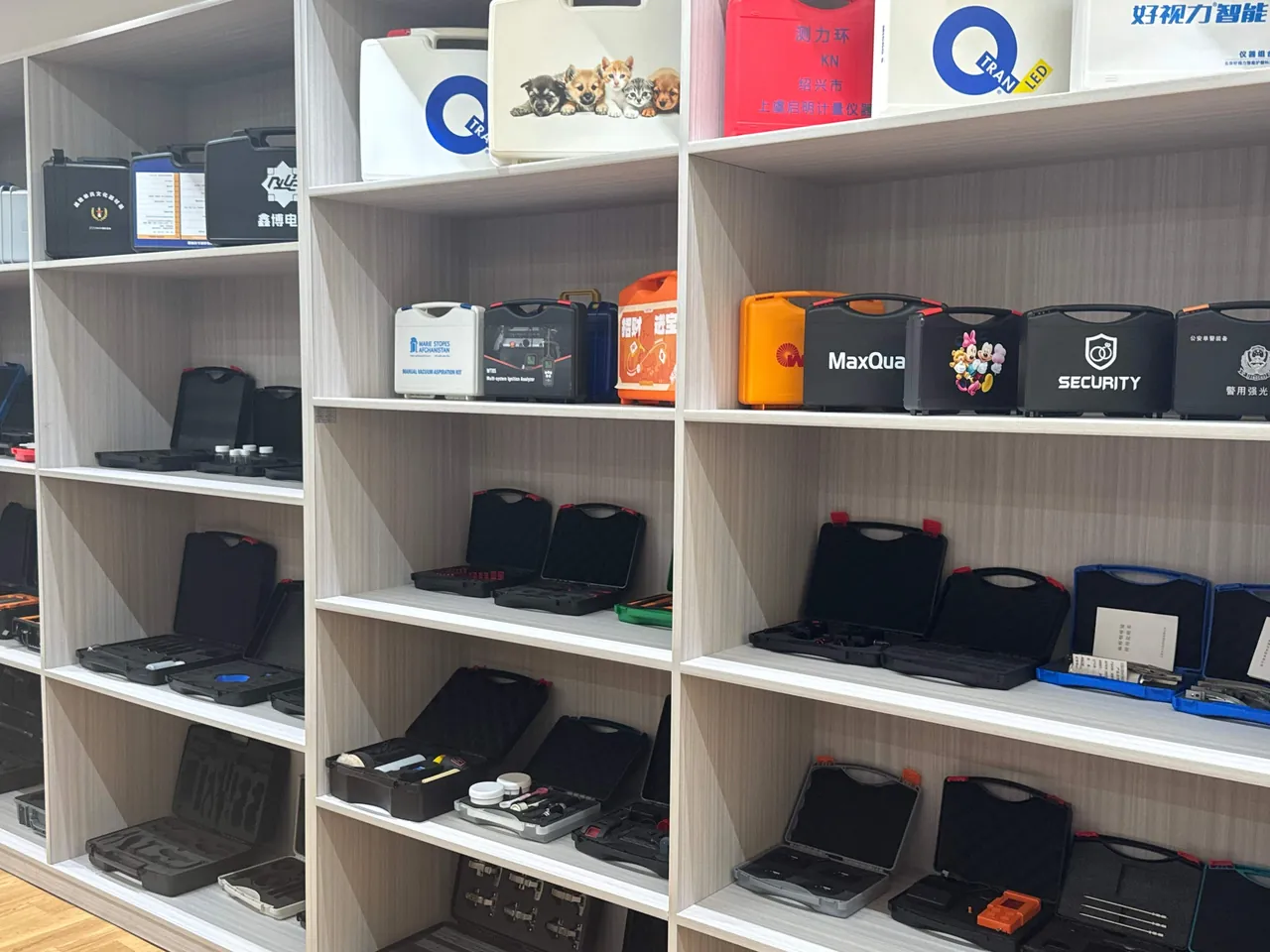
Base resins fall into four families: polypropylene, polyethylene, predominantly HDPE, ABS and polycarbonate. None is absolutely better; they differ only in fit to a load spectrum.
Polypropylene is the highest volume case material. At 0.90 to 0.91 grams per cubic centimetre it is the lightest of the four, so a case can be lighter or the wall thicker within the same weight budget. Copolymer PP reaches notched impact of 20 to 40 kilojoules per square metre at room temperature and keeps useful toughness when toughened through ethylene segments. Chemical resistance is good apart from strong oxidising acids. The drawback is directional shrinkage of 1.0 to 2.5 percent, differing by more than half a point between flow and transverse directions.
Polyethylene is the most stable at low temperature. HDPE can embrittle below minus seventy degrees and still fails ductile at minus forty, so polar, high-latitude and high-altitude winter work defaults to PE. Its flexural modulus of 800 to 1400 megapascals makes it slightly less rigid than PP, and creep under sustained stacking is more pronounced. Shrinkage of 1.5 to 4.0 percent is the hardest to control, so large PE cases usually take the rotational route. ESCR varies enormously between grades and must be screened by standard test methods rather than melt flow rate.
ABS earns its place through dimensional accuracy and surface quality. Shrinkage of only 0.4 to 0.7 percent gives stable dimensions and low warpage, suiting shells where metal hinges, latches and seals mount. Its weakness is weatherability: the double bonds in the butadiene segment are readily attacked by ultraviolet, so an unstabilised outdoor case yellows and loses impact strength within half a year.
Polycarbonate is the ceiling on impact at 60 to 90 kilojoules per square metre, with high transparency. It carries two drawbacks: notch and solvent sensitivity, so stress cracking appears on contact with certain oils, cleaners or plasticisers when stress is present; and hydrolytic sensitivity, with molecular weight falling in hot humid conditions. PC therefore serves in inspection windows and instrument covers rather than whole bodies.
| Property | PP Copolymer | HDPE | ABS | PC |
|---|---|---|---|---|
| --- | --- | --- | --- | --- |
| Density g/cm3 | 0.90-0.91 | 0.94-0.97 | 1.04-1.06 | 1.20 |
| Yield strength MPa | 25-35 | 20-30 | 40-50 | 60-70 |
| Flexural modulus MPa | 1000-1600 | 800-1400 | 2000-2600 | 2300-2400 |
| Notched impact kJ/m2 | 20-40 | 10-40 | 15-25 | 60-90 |
| At minus forty | Needs toughened grade | Excellent | Moderate | Good |
| Heat deflection C | 90-110 | 70-85 | 85-100 | 130-140 |
| Shrinkage percent | 1.0-2.5 | 1.5-4.0 | 0.4-0.7 | 0.5-0.7 |
| Weathering unmodified | Moderate | Moderate | Poor | Moderate |
| Recycling code | 5 | 2 | 9 or 7 | 7 |
Toughening, Filling and Modification Systems
Base resin is rarely used alone. Case compounds are modified grades, and the modification system decides whether a material suits a given scenario.
Toughening is the first tool for low-temperature service. PP commonly uses an ethylene-propylene copolymer or a polyolefin elastomer at 8 to 25 percent. The modifier disperses as sub-micron particles and, under load, triggers crazing and shear bands that absorb impact energy. More is not automatically better: past a critical loading, modulus and heat deflection temperature drop, stacking stiffness suffers, and rising melt viscosity makes filling harder. The method is to fix the target impact figure, back-calculate the minimum loading, and find the knee on the stiffness-toughness curve.
Fillers restore stiffness. Talc at 10 to 30 percent raises PP flexural modulus by 40 to 80 percent and lowers shrinkage, at the cost of impact strength and gloss. Short glass fibre is more efficient, with 15 to 30 percent pushing modulus above 3000 megapascals, but fibres orient along flow, causing anisotropic shrinkage, warpage and exposed fibre that spoils sealing face contact, so glass suits internal parts rather than appearance shells.
Functional modification covers antistatic and conductive systems holding surface resistivity between ten to the sixth and ten to the ninth ohms; flame retardant systems targeting UL 94 V-0 or V-2 where flame risk or transport certification applies; weathering systems, covered below; and masterbatch. One caution matters: many pigments antagonise UV stabilisers, and some organic reds and yellows accelerate photo-ageing, so outdoor dark cases must be validated at colour selection stage rather than after production starts.
Regrind blending trades cost against performance. First-pass regrind from in-house runners, gates and rejects can be blended under strict ratio and traceability control, normally under 15 percent and never in critically loaded areas. Second-pass recycle, with unknown origin and broad molecular weight distribution, should not enter primary load-bearing parts. After blending, low-temperature impact and ESCR must be re-verified; the virgin property sheet cannot stand in for measured values.
Injection Moulding: Wall Thickness, Flow and Shrinkage Control
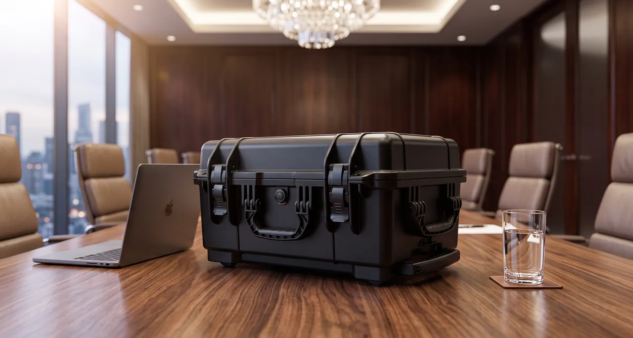
Injection moulding is the mainstream process for high-volume cases, with cycle times of 40 to 120 seconds.
Filling is governed by flow length ratio, the distance melt travels from gate to fill end divided by wall thickness, roughly 200 to 300 for PP, 200 to 280 for HDPE, 150 to 220 for ABS and 100 to 150 for PC. A large case on a single gate often exceeds it and short shots. The remedy is more gates or sequential valve gate control on a hot runner, but more gates means more weld lines. A weld line is the weak interface where two flow fronts meet, typically only 40 to 70 percent of base strength, and it appears behind holes, inserts and grilles, where load is sensitive. Layout should move holes and inserts away from likely weld sites, or use overflow wells to push the line into a non-loaded area.
Shrinkage control needs resin shrinkage, holding compensation and mould allowance together. Holding feeds material into the cavity until the gate freezes, normally at 40 to 80 percent of primary injection pressure. Insufficient holding gives sink marks; over-holding builds residual stress around the gate and makes ejection difficult. Cavity dimensions are scaled by measured shrinkage, fixed through trial iteration rather than taken from a property sheet, because one grade can differ by 0.3 percentage points across different walls, gates and mould temperatures.
Internal stress comes from uneven cooling and excessive molecular orientation. Low mould temperature freezes the skin quickly and constrains core shrinkage, creating tensile stress; excessive injection speed builds an oriented surface layer that cracks when heated or exposed to solvent. Mitigation uses higher mould temperature, 30 to 60 degrees for PP and 60 to 80 for ABS, staged injection speed, and post-mould annealing. For shells assembled at a sealing face, control is critical because stress release keeps flatness drifting for days after shipment.
The tool itself is part of selection. Cavity count sets amortised unit cost but brings fill imbalance, needing balanced runners and fill analysis. Features needing reaming, tapping or inserts require slides and lifters that push cost up sharply. Gas-assisted and microcellular moulding core out thick sections, cut weight and remove sink marks, suiting handles and frames.
Rotational Moulding: Large Cases and Uniform Wall Advantage
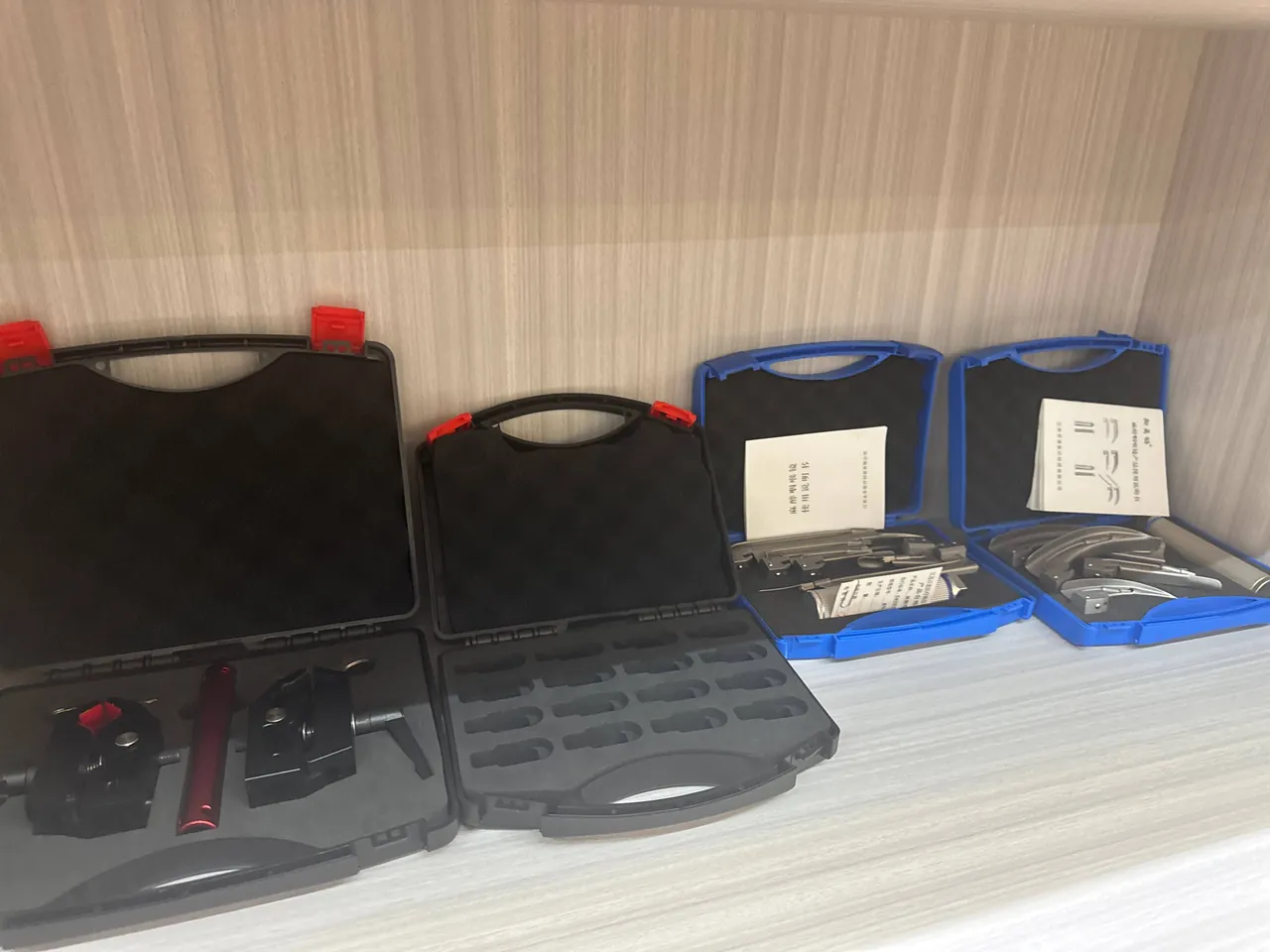
Rotational moulding charges a measured quantity of polyethylene powder into a closed mould, rotates it about two perpendicular axes in a heating oven so the powder coats the cavity wall layer by layer, then transfers it to a cooling station. The cycle is long, typically 15 to 40 minutes, but the four advantages are exactly what injection struggles to deliver.
Wall uniformity comes first: the process builds up layer by layer, so there is no end-of-fill thinning from flow decay, and variation within one part stays inside plus or minus 10 percent. Second, no weld lines, no gates and no orientation, so the shell is one continuous structure with consistent properties in all directions. Third, very low residual stress, since the process runs at atmospheric pressure with slow cooling. Fourth, low tooling cost, because a rotational tool carries only its own weight and powder friction, welded steel plate or cast aluminium costing one fifth to one tenth of an equivalent injection tool, suiting annual volumes of a few hundred to a few thousand and small-batch validation before production tooling.
Dimensional tolerance is typically plus or minus 1 to 2 percent against 0.3 to 0.5 for injection, so sealing faces, hinge seats and latch mounting faces almost always need secondary machining. Surface quality shows natural orange-peel inside, and a high gloss finish is not achievable. On materials the process is essentially limited to polyethylene: PP can be rotationally moulded but has a narrow window and prominent brittleness, and ABS and PC are basically unsuitable.
Wall thickness is commonly 4 to 8 millimetres, far thicker than injection, bringing impact resistance and stiffness at the cost of weight and cooling time, and the process can also produce double-wall structures with a hollow or foam-filled core. Inserts are another strength: brass nuts, stainless thread sleeves and embedded steel plates fixed in the cavity before charging end up encapsulated by the melt, forming a robust connection that matters for heavy cases whose castors are removed repeatedly.
Extrusion Sheet and Welding Route
For annual volumes of only a few dozen, or cases beyond the capacity of injection and rotational machines, the extruded sheet and welding route is pragmatic. It needs no tooling investment and suits prototype stages and non-standard custom work.
The process extrudes or buys PP or HDPE sheet, commonly 3 to 15 millimetres thick, cuts it to a developed pattern by CNC, thermoforms the folds, then joins the pieces by welding. Hot gas welding uses a rod of the same material heated with a hot air gun and pressed together; equipment is cheap and it suits site work, but seam quality depends heavily on operator skill and the strength factor is usually 0.6 to 0.8. Extrusion welding feeds molten material continuously into a prepared groove, giving high efficiency and stable quality on long straight seams. Ultrasonic and vibration welding suit small areas but need heavy investment and are limited on large cases.
The seam is the lifeline of this route. Place seams in low-stress areas away from corners and handle roots; use double-sided groove welds rather than single-lap joints, with lap width not less than three times sheet thickness; and match rod to parent material and grade, since PP rod on PE sheet will almost certainly crack. Inspection should sample important seams for tensile shear testing with strength not below 60 percent of the parent and leak test seal seams with soapy water bubble or pressure decay methods.
A welded sheet case is not inherently inferior in stiffness to an injection moulding, because sheet can be thicker and external frames added more easily; its weaknesses are poor consistency, rough appearance and high labour content. The common path is to freeze requirements and validate structure with welded parts, then move to rotational or injection moulding for production.
Structural Wall Design and Rib Layout
Plastic cases gain stiffness through structure, which is the biggest mindset difference from metal case design. Thickening alone is inefficient: bending stiffness rises with the cube of thickness, but weight and cooling time grow in proportion. The correct method is to raise section moment of inertia with ribs.
Usual wall thickness is 2.5 to 4.0 millimetres. Below 2.5 causes filling difficulty and inadequate strength; above 4.0 lengthens cooling time and raises sink and void risk. Thickness must be as uniform as possible, with generous transition length where it changes. Rib thickness is 0.5 to 0.6 of wall thickness, the empirical value that prevents sink at the root; rib height should not exceed three times wall thickness; draft is 1 to 2 degrees per side; and the root radius is 0.25 to 0.5 of wall thickness, since an inadequate radius becomes a crack origin under impact.
Rib layout follows the load path. Under stacking, load travels down the side walls into stacking bosses and the base support face, so side walls should be dominated by vertical ribs. The base carries payload weight and drop impact and suits a grid of ribs that spreads concentrated load. The lid is a compression member during stacking, and its ribs should align with the side wall ribs to form a continuous load column. That alignment principle, with lid ribs, side wall ribs and base support faces as collinear as possible vertically, can raise stacking capacity by more than 30 percent.
Corners are another critical area, since corner drops concentrate energy most severely. They should be thickened to solid or near-solid sections with outside radius not less than 1.5 times wall thickness, and ribs extended into the corner for triangular support. Handles and castor seats are concentrated load areas, so the shell behind them needs a reinforcing grid and metal inserts to spread stress, with hole edge distance not less than 1.5 times hole diameter. Process capability at these areas is covered further in Toolbox Durability and Load Testing.
Weathering System: UV Stabiliser and Thermal-Oxidative Ageing
For cases serving outdoors, the life bottleneck is usually ageing rather than mechanical strength. Ultraviolet photon energy breaks polymer chains and starts free radical reactions that appear as chalking, discoloration and crazing, plus a cliff-edge fall in impact strength. More insidiously, ageing first forms a degraded surface layer a few hundred microns thick that becomes the crack initiation site, so a modest drop can trigger a through-thickness fracture.
Two routes exist, blocking and capture. Carbon black is the most efficient and cheapest light screen: well-dispersed fine carbon black at 2 to 2.5 percent gives extremely long outdoor life. Hindered amine light stabilisers capture free radicals and decompose hydroperoxides cyclically, typically at 0.2 to 1.0 percent, and are colour independent; but they are alkaline and deactivated by halogenated flame retardant systems, acidic pigments and acidic cleaners, so a low-alkalinity grade is needed. Ultraviolet absorbers of the benzotriazole and benzophenone types absorb UV and dissipate it as heat, suiting thick sections but offering little on thin walls.
Thermal-oxidative and photo-ageing usually add up, with processing degradation, long-term oxidation in storage and outdoor ultraviolet all consuming the antioxidant package. Systems normally combine a hindered phenol primary antioxidant with a phosphite secondary antioxidant.
Verification uses xenon arc artificial weathering to GB/T 16422.2 or ASTM G155, and fluorescent UV ageing to GB/T 16422.3 or ASTM G154. Xenon spectra are closer to sunlight and suit colour and overall property assessment; fluorescent UV gives a higher acceleration factor and suits rapid screening. Judgement must not rest on colour difference alone: impact strength retention, generally at least 70 percent after the set dose, has to be measured alongside, with no chalking or crazing. Correlation with natural exposure varies by material, so important projects should hang comparison racks at an exposure site. Selection for tropical and high-altitude service is covered in Outdoor Cases in Temperature Extremes and Engineering Plastics for Outdoor Cases.
Process Links to Sealing Face and Assembly Precision
Whether a case reaches its intended protection rating is usually decided not by the gasket but by the flatness and dimensional stability of the sealing face. A gasket fills a gap, but only a limited one: usable compression of a solid rubber strip is generally 15 to 30 percent, and beyond that compression set accelerates and closing force rises sharply.
Loss of flatness has three sources. Moulding warpage from uneven cooling, directional shrinkage and poor rib proportions is the first. Assembly deformation is the second, where the lid deflects locally under latch preload and gasket reaction, especially with wide latch spacing, so spacing is normally kept under 250 to 350 millimetres with a latch point mandatory at each corner. Time-dependent drift is the third, so critical parts should be conditioned before assembly.
The dimension chain needs working out in advance. Case mouth width, lid spigot width, groove depth, seal cross-section diameter and latch compression travel form a closed chain whose tolerances must stay inside the compensable range of the gasket. Practice is to set shell tolerance from process capability, plus or minus 0.3 millimetres per 100 millimetres for injection and 0.5 for machined rotational parts, then set groove and seal tolerances from that. Groove width is usually 1.05 to 1.15 times cord diameter and depth 0.6 to 0.75 times, giving room for lateral expansion under compression.
Several process details are easily missed: the sealing face should be an independent temperature control zone in the tool for even cooling; the face must be free of ejector marks, weld lines and flash; and the parting line must not fall on it, or the shut line becomes a leak path. System-level method and criteria are given in System-Level IP67 Protection Design and Toolbox Hinge, Latch and Seal Coordination.
Low-Temperature Impact and Drop Verification
Low temperature is where plastic cases most often come unstuck: every polymer has a ductile-to-brittle transition, below which failure changes from shear yielding to rapid craze-crack propagation, with notched impact able to fall by an order of magnitude. Verification therefore cannot be just cooling to minus forty and dropping once; it needs a temperature gradient test that locates the transition point and confirms service temperature sits inside the ductile region.
Test design must be realistic about conditioning. Samples need long enough at the target temperature for the whole section to equalise, usually not less than 30 minutes per millimetre of wall and not less than 4 hours, and drops should be completed within 30 seconds of removal or performed inside a cold chamber so warming does not falsify results. Attitudes follow the standard: one corner, three edges, six faces, with height graded by mass and a concrete or steel impact surface.
Criteria must be more than does not break. A sound set covers no through-thickness shell crack; no closure failure from sealing face deformation; no loosening or cracking of latches, hinges and their mounting areas; and peak response at the simulated payload, or measured by accelerometer, within the permitted value. Where precision equipment is carried, controlling acceleration response beats controlling drop height: place a three-axis accelerometer in the case, measure the shock spectrum at the equipment base, and back-calculate the cushioning thickness needed.
Falling weight impact testing to GB/T 9639 or ASTM D5420 suits rapid screening, taking specimens at each temperature and reading the transition temperature off the plotted curve. That curve turns low-temperature behaviour into a comparable number, useful for choosing between grades and setting incoming thresholds. Full package verification can additionally reference the ISTA series and GB/T 4857 series, and Rotational Versus Injection Moulded Cases compares how the two routes behave under these tests.
Recyclable Marking and Whole-Life Management
Where a plastic case goes at end of life is moving from an afterthought to a hard line in purchase terms. GB/T 16288 sets the recycling mark, with PP at 5, HDPE at 2, and ABS and PC generally at 7 for other. The mark does not affect performance, but it decides whether recycling can sort efficiently, so mark and code should be engraved into the tool on a non-appearance face at tooling stage.
Design for recyclability has four principles. Single-material construction comes first: body, lid and hinge should share one base polymer, for example an all-PP scheme with an integral living hinge, avoiding the sorting difficulty of a PP shell with a polyamide hinge and an elastomer seal. Fewer metal inserts comes second, since brass nuts and stainless shafts damage granulating equipment and should be removable. Third, avoid irreversible composites: painting, plating and laminated foil badly degrade recyclate quality, so prefer self-coloured material. Fourth, control the filler system, since high glass and mineral loading lowers recyclate properties.
Recyclate use is closing the loop. Post-consumer recyclate, after sorting, washing, melt filtration and restabilisation, can partly replace virgin material in non-critical parts, while in-house offcuts can be reground and reused at a controlled ratio. Management needs batch traceability recording source, batch, blend ratio and property verification data. For carbon footprint, recyclate use and lightweighting through thinner walls and cored heavy sections are the two most direct levers.
The whole-life view also includes repair and spares. Replaceable latches, hinges, castors and sealing strips can more than double case life, and those spares should follow the same single-material and easy-disassembly principles. Putting the spares list and replacement intervals into case documentation is the service item users notice most readily. Material selection detail is extended in Protective Case Plastic Materials and Plastic Functional Box Structure and Application.
Selection Workflow and Tooling Decision
Pulling the preceding points together, plastic case selection advances in five steps.
Step one is environment and load definition, producing a list covering temperature range, drop height, stacked layers, ultraviolet dose, chemical media and retrieval frequency, plus payload weight, centre of gravity and permitted acceleration. Step two is material pre-screening, scoring low-temperature toughness, stiffness, chemical resistance and weatherability, shortlisting two or three candidates and requesting measured rather than nominal data. Step three is process route selection, deciding between injection, rotational moulding and sheet welding on volume and size while estimating tooling investment and unit cost. Step four is structural design and simulation, completing wall thickness, ribs, corners, handles and mounting areas. Step five is prototype verification and acceptance, measuring the agreed drop, stacking, sealing and ageing items and issuing an acceptance report before releasing production.
| Annual Volume | Process | Tooling Cost | Unit Cost | Accuracy |
|---|---|---|---|---|
| --- | --- | --- | --- | --- |
| Under 100 pieces | Sheet welding | Almost nil | High, labour dominated | Low |
| 100 to 2000 pieces | Rotational moulding | Low | Medium | Medium, faces machined |
| 2000 to 10000 pieces | Rotational or simple injection tool | Medium | Medium low | Medium |
| Over 10000 pieces | Multi-cavity injection | High | Low | High |
The core of the tooling decision is payback. An injection tool costs a lot but gives low unit cost, a rotational tool costs little but gives higher unit cost, and the curves usually cross around a few thousand pieces. The calculation must include secondary machining, assembly labour, scrap rate and tool maintenance. Change cost is routinely underestimated: once an injection tool is built, structural change often needs rework or a new tool, whereas rotational and welded routes are far more flexible. Projects whose requirements are not frozen should validate with rotational moulding or welding first. More on lead time, tooling and acceptance is available in Custom Case Prototyping Timeline, How to Choose a Case OEM Factory and AQL Acceptance for Custom Cases.
Frequently Asked Questions FAQ
Q: For winter transport in northern regions, should PP or PE be preferred?
A: The first question is which side of the ductile-to-brittle transition the service temperature falls on. HDPE can embrittle below minus seventy degrees and still fails in a ductile manner at minus forty, which makes it the default for polar, high-latitude and high-altitude winter work. Toughened copolymer PP covers routine winter conditions down to minus twenty or minus thirty, and it is stiffer and more heat resistant than PE, so it stacks better. The engineering method is to take two or three candidate grades and run falling weight or notched Charpy impact tests at minus forty, minus twenty, zero and twenty-three degrees, plot impact strength against temperature, read off the transition temperature, then require the lower service temperature limit to sit ten to fifteen degrees above it as a safety margin. Where the case also resists long-term stacking, the stiffness lost by switching to PE must be bought back with ribs and thicker walls rather than accepted silently. Grades should be rechecked after heat ageing, because stabiliser consumption shifts the curve.
Q: Can cracking at an injection moulded weld line be solved by increasing wall thickness?
A: Thickening only delays the problem, it does not cure it. A weld line is the weak interface where two flow fronts meet, typically only 40 to 70 percent of base strength; thickening lowers nominal stress but does nothing for interfacial strength, and it adds longer cooling time, sink marks and higher residual stress. The correct approach works on three fronts. First, move or add gates so the weld line is pushed into a non-loaded area, or use overflow wells to flush the weak interface into scrap. Second, raise melt and mould temperature so the fronts are still hot when they meet, improving interdiffusion of the chains. Third, at layout stage move holes, inserts and grilles away from positions where a weld line is likely to form. Only the three together bring risk down to an acceptable level, and verification should drop test samples from the production tool rather than a prototype made another way, since laboratory plaques rarely reproduce the weld strength of a real moulding.
Q: How do you really choose between rotational moulding and injection, is volume alone enough?
A: Volume is the main criterion but not the only one; size, wall uniformity requirements and change risk matter too. Rotational moulding offers low tooling cost, typically one fifth to one tenth of an equivalent injection tool, uniform wall within plus or minus 10 percent, no weld lines, low residual stress and the ability to embed metal inserts, which suits large cases, small batches and projects whose requirements are not yet frozen. Its drawbacks are a long cycle of fifteen to forty minutes, loose tolerance of 1 to 2 percent, orange-peel surface, material choice essentially limited to polyethylene, and mandatory secondary machining on key fitting faces. Injection offers high dimensional accuracy, short cycles and a wide material choice, suiting high volume and tight fits, but at high tooling investment and high change cost. The common path is to validate and deliver small batches with rotational moulding, then transfer to injection once requirements are frozen and volume justifies the tool. Confirm the decision with a costed comparison that includes machining and scrap, not tooling price alone.
Q: Should mould shrinkage compensation be taken from the property sheet value?
A: No, the nominal figure cannot be used directly. A property sheet shrinkage is measured on a standard specimen under standard conditions, whereas real shrinkage is influenced jointly by wall thickness, gate type, injection speed, holding pressure and time, mould temperature, and fibre or filler orientation; the same grade can differ by 0.3 percentage points between structures, already fatal for a shell with tight dimensional requirements. The correct method is to scale the cavity by an empirical value for a first trial, measure the critical dimensions, back-calculate actual shrinkage, and rework the tool, which normally takes one or two iterations to converge. Shrinkage is also directional, so cavity length and width must be scaled by different values or the part will warp. Where glass fibre is present the anisotropy is larger still and deserves its own measurement programme. Where the case is used outdoors, the same review should include UV exposure, because a shell that has chalked will lose surface strength long before it loses shape. Q: Does more UV stabiliser always mean longer outdoor life?
A: No, the relationship is not linear and overdosing is harmful. Hindered amine light stabilisers are normally used at 0.2 to 1.0 percent and ultraviolet absorbers at 0.1 to 0.5 percent; above those limits blooming, antagonism with pigments or other additives, and pointless cost escalation appear. System synergy matters more than quantity. Hindered amines are alkaline and are deactivated by halogenated flame retardant systems, acidic pigments and acidic cleaners, so a low-alkalinity grade is required. Some organic red and yellow pigments accelerate photo-ageing rather than resisting it. Carbon black is the most efficient light screen, with 2 to 2.5 percent giving extremely long life, but it restricts colour. The judgement criterion is impact strength retention after ageing, generally at least 70 percent, checked together with colour difference and the absence of chalking or crazing, on the production colour rather than a natural sample. Keeping a record of the mould cavity used for each batch also makes it easier to trace a dimensional drift back to a specific tool. Q: Why does a case still leak after the sealing strip has been replaced?
A: The fault usually lies in the sealing face and closing force rather than in the strip. Usable compression of a solid rubber strip is generally 15 to 30 percent: beyond that, over-compression accelerates compression set and sharply raises closing force so the lid deflects, while under-compression leaks directly. If flatness is out of control through moulding warpage or assembly deformation, the local gap exceeds what the strip can compensate. Troubleshooting starts by measuring flatness and the mouth dimension chain, then checks latch spacing, normally not more than 250 to 350 millimetres with a latch point at every corner, whether the hinge has play, and whether the lid shows visible deflection when closed. Groove dimensions must also match: width 1.05 to 1.15 times cord diameter and depth 0.6 to 0.75 times, leaving room for lateral expansion under compression. Finally confirm that no ejector mark, weld line, flash or parting line crosses the sealing face, and record flatness before and after closing so the deformation source is identified rather than guessed.
Q: What practical meaning does the recycling mark have for the user?
A: The mark matters in three phases: compliance, repair and end-of-life handling. GB/T 16288 assigns 5 to PP, 2 to HDPE and 7 to ABS and PC, and buyers often have to submit material composition and mark data for environmental filings and green supply chain audits. In repair, the mark identifies the shell material so maintainers choose compatible welding rod, adhesive and spares, because PP rod used to patch a PE body will almost certainly crack. In end-of-life handling, a single-material design such as an all-PP case with an integral living hinge sorts far more efficiently than a PP shell with a polyamide hinge and an elastomer seal, and the recyclate quality is better as well. Mark and material code should be engraved into the tool on a non-appearance face, and the same logic applied to spares so the whole product stays sortable. Where parts are sourced from more than one plant, the same approval should be repeated per plant rather than assumed to transfer. Q: How should acceptance criteria be set for a custom plastic case project?
A: Criteria must be quantified and repeatable, not phrased as vaguely as no damage. Four layers are recommended. The first covers appearance and dimensions: no flash, no sink marks, no cracked weld lines, critical fit dimensions inside tolerance, and sealing face flatness to specification. The second covers mechanical performance: after conditioning at the agreed temperature, run one-corner, three-edge, six-face drops with no through-thickness shell crack and no loosening of latches, hinges or their mounting areas, then stack test at the rated layer count and duration with the lid still opening normally and no permanent deformation. The third covers protection performance: dust and water testing to IEC 60529 or GB/T 4208, or rain and air leak testing as substitute criteria where full immersion is inappropriate. The fourth covers material performance: low-temperature impact, strength retention after ageing and environmental stress cracking sampled against the grade specification. State the sampling plan and acceptable quality level for all four layers, and attach the reports to the case serial number so field failures can be traced back to a material lot.
Conclusion and Related Reading
JUNZHIJIA matches resin grade, moulding route and rib structure to measured service conditions, delivering custom tooling, liner layout and OEM/ODM with material certificates, ageing and drop reports, recycling marks and spares lists.
Related Reading