

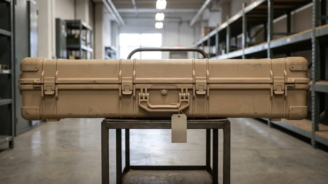
In the world of specialized storage, transport and defense trade support, Ammunition and Nuclear Ordnance Boxes, Explosive Container products, Missile Container and Missile Box systems, Missile Warhead Container designs and the Military Chemical Agent Container family all belong to one engineering discipline: protective container design for highly sensitive materials. What separates them from ordinary ammunition crates is not the footprint but the design objective. An ordinary crate has to be strong enough, portable enough and durable enough. A specialized container must simultaneously satisfy verifiable engineering constraints across shell stiffness, sealing and pressure equalization, static dissipation and grounding, electromagnetic shielding, thermal control, vibration damping and restraint, flame retardance, locking and tamper evidence, traceability marking, certification and load planning. Each of those constraints needs drawings, material records and test evidence behind it. JUNZHIJIA, manufactured by Kexin New Materials (Guangdong) Co., Ltd., develops this class of case along a fixed path: define the protection envelope, then implement structural means layer by layer, then close the loop with test data. This article discusses only the structure and functional design of the packaging container itself (case, box or cabinet). It does not address any material properties or handling questions. Specific storage and transport must follow local regulations and export control requirements.
This article is written for specialized storage and transport units, defense trade integrators, and procurement engineers responsible for packaging sensitive materials. It walks through the container by function rather than by part list, and it deliberately stays on the engineering side: how the case is designed, never what is placed inside. Readers can treat it as a functional checklist. Decide which functions your scenario actually needs, then match them to structural approaches, material directions, test items and certification routes, and turn that into your own technical requirement document. A FAQ section and related reading follow at the end.
What Counts as a Special Ordnance Container
Before treating this as a product category, it helps to draw its boundary. A special ordnance container is a case, box or cabinet delivered as a protective container for sensitive storage and transport scenarios. Its shared traits are high unit value, severe consequences of failure, a long regulatory chain, and strict verification demands. Stacked together, those traits push the design center of gravity away from cost and volume and toward control and provability: every protection claim must be demonstrated by test, and every material and structure must be traceable through drawings and batch records.
In engineering terms, the category usually varies along four axes: payload geometry (long, disc shaped, cylindrical or irregular), protection emphasis (sealing first, shielding first, thermal control first, or shock resistance first), duty cycle (high frequency rotation versus long term storage), and the applicable regulatory chain (whether export packaging certification, special seals and ledgers are required). Crossing those four axes produces very different requirement sets. A case built around long term storage will weight humidity control and seal aging far more heavily. A case built around transit across climate zones will make pressure equalization and thermal cores the design spine. A case built around frequent handling must balance locking reliability against open-close durability.
Once the boundary is clear, the design language becomes clear too. This category does not pursue "thicker is safer." It pursues one clear responsibility per layer. The shell carries overall stiffness and puncture resistance. The seal system blocks water vapor and dust. The valve and membrane manage differential pressure. The liner handles electromagnetic and static behavior. The core manages temperature. Cushioning and restraint manage shock and displacement. Locks and seals manage access control. Marking and traceability manage the chain of responsibility. Define those responsibilities separately and verify them separately, and the protection capability of the whole case becomes a computable, reproducible system rather than a pile of materials.
The Protection Matrix: Mapping Requirements to Structural Targets
Before design begins, building a requirement-to-target matrix is the single most useful habit in this category. The method is to translate each usage scenario into measurable container targets, then assign a structural means, a material direction, a test item and an acceptance criterion to each one. The value is change management: when a requirement shifts, the team knows exactly which layer to revise instead of rebuilding the whole case.
The usual form is a two dimensional matrix. The rows are protection dimensions: sealing and pressure equalization, static dissipation, electromagnetic shielding, thermal control, vibration and shock, flame retardance, locking and tamper evidence, traceability marking, and stacking and load planning. The columns carry five fields: scenario requirement, structural means, material direction, test item, and acceptance criterion. Take the sealing row. The scenario requirement might be "prevent liquid water and dust ingress during air transit across climate zones." The structural means would be a compression designed seal groove and gasket plus a pressure equalization valve. The material direction would be silicone or EPDM gaskets plus a waterproof breathable membrane. The test items would be a seal integrity test and a pressure cycle test. The acceptance criteria would state explicit leak rates and cycle counts.
The matrix does a second job as well: it exposes conflicts. Protection dimensions often pull against each other. Increasing seal compression helps against moisture but raises opening force and gasket fatigue. Thickening a shielding liner helps attenuation but can squeeze the thermal core. Stiffening the shell helps against shock but adds mass and handling burden. Putting those conflicts on one page lets the team make trade-offs during concept design rather than discovering at the prototype stage that something has to be sacrificed. JUNZHIJIA generally issues this matrix as the first annex to the technical agreement, signed off jointly with the customer before structural design starts.
Sealed Shells and Pressure Equalization: Valves, Membranes and Compression
Sealing is the most fundamental and most easily underestimated layer of a specialized container. The goal is not simply water resistance but isolation of the internal microclimate from the outside: blocking liquid water, water vapor and dust while avoiding structural stress when ambient pressure changes. Those two jobs must be designed together, because sealing without equalization turns a differential pressure into a load on the shell. The case can bulge or collapse, seals can fail, and hinges and latches can deform under load.
The sealing design of the shell has three parts. The first is geometric matching between groove and gasket: groove depth, groove width and cord diameter should define a stable compression band so that the gasket sits in its elastic working range when the latches close, neither under compressed nor crushed. The second is gasket material and aging control. Silicone offers a wide temperature range and stable rebound, while EPDM offers strong weather and ozone resistance. Either must be selected against the expected temperature band and service life, with hardness and compression set written into the acceptance criteria. The third is uniformity of clamping force. A gasket only works when compressed evenly around its full perimeter, so latch count, spacing and lid stiffness must be coordinated. Otherwise a leakage path appears where the middle is tight and the corners are loose.
The pressure equalization valve is the companion component of the seal system. It vents slowly through a waterproof breathable membrane when a pressure differential appears while blocking liquid water and dust. Three points matter in selection: matching air flow to internal volume, the water resistance rating against the expected altitude or temperature span, and how the valve mounting location affects seal integrity. The mounting hole is itself a potential leak point and must be protected by a gasket and a positive stop structure for long term reliability. For cases meant for long term storage, internal desiccant and humidity indicators should be added so a manager can read the internal state without opening the case, keeping the cost of "opening breaks the microclimate" as low as possible.
Static Dissipation, Conductive Paths and Grounding
The static requirement for sensitive material containers is essentially a demand that the container itself provide a controlled charge dissipation path. If the shell and liner are insulators, charge generated by friction, separation and induction accumulates locally and builds a potential difference. The correct approach is to use conductive materials and a grounding structure so that charge bleeds away in a controlled manner to a reference potential, rather than discharging abruptly across a gap or between metal parts.
The implementation usually works in three layers. The first is surface conductivity. Interior walls, liners and dividers can use materials with conductive fillers, or composite conductive fabrics and conductive coatings, so that surface resistance falls within an agreed engineering band instead of behaving as an insulator. The second is volume conductivity and equipotential bonding. All conductive parts, including metal inserts, fasteners, handles and wheel sets, should be bonded to each other through conductive structure to form one equipotential body, preventing potential differences between parts. The third is a grounding interface. The case should provide a clearly marked grounding terminal or contact point so operators can tie the case into the site grounding system.
Several traps recur. One is treating black material as conductive material; color says nothing about conductivity, and selection must rest on resistance test data. Another is ignoring the insulating effect of coatings and anodized layers, so a shell that looks metallic is actually non conductive and needs dedicated conductive paths at critical contact points. A third is placing the grounding terminal somewhere inconvenient, so it goes unused. A fourth is omitting an equipotential bond between liner and shell, leaving the liner as an isolated charged body. Fold those three layers and four traps into the drawings and inspection checklist, and static protection becomes real rather than a material grade on paper.
EMI Shielding: Liners, Gaskets and Aperture Control
Electromagnetic shielding is another dimension that is easily treated as an add-on. Its goal is to suppress electromagnetic coupling between the inside and outside of the case: reducing interference from the external electromagnetic environment and limiting leakage of any internal electromagnetic activity. For container engineering, shielding is not simply making a metal box. What determines shielding effectiveness is usually the seams, apertures and interfaces, not the intrinsic performance of the material.
The core principle is continuity first. A solid plate of metal or conductive composite can reach high attenuation, but a real case always has a lid seam, hinge lines, a valve port, handle holes and a marking window, and those discontinuities become leakage paths. Three techniques are used to close them. The first is a conductive gasket that merges sealing and shielding, maintaining both air tightness and electrical continuity under compression. The second is conductive padding and finger stock at lid and door seams, joining the conductive faces of lid and body through multiple contact points. The third is shielding mesh and conductive viewing windows for locations that must transmit light or air, using a grid structure to preserve continuity.
Liner selection involves trade-offs by scenario. Conductive fabric liners are compliant and cover irregular cavities easily, which suits designs that prioritize assembly convenience. Metallized film or conductive coatings are advantageous on thin walled structures. Metal mesh and foil laminates appear where higher attenuation is required. Note that shielding effectiveness is a curve across frequency, and performance differs sharply between bands, so it must be evaluated across the frequency range that actually matters rather than against a single figure. Compatibility with the static dissipation path also matters. If the two conflict, resolve it by layering and a shared grounding point rather than letting each path go its own way.
Thermal Management: Insulation Cores, Barriers and Heat Spreading
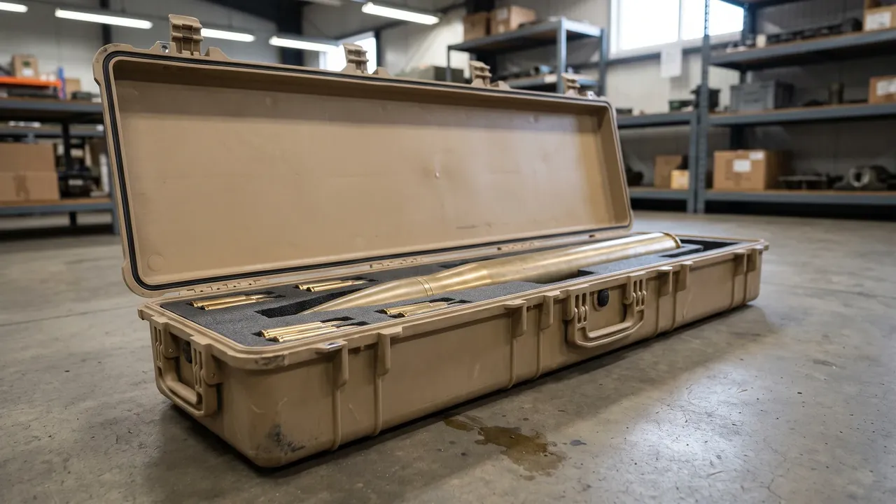
Thermal control is the most system level layer of a specialized container. What it usually has to deliver is not refrigeration but slowing the rate of temperature rise and fall and narrowing the amplitude of fluctuation, so that day-night swings, transit compartment changes and temporary ground storage have less effect on the interior. Container engineering here does passive thermal management: using insulation and thermal mass to flatten the internal environment rather than relying on external energy.
The base structure is a three layer sandwich. The outer layer is the load bearing shell for stiffness and protection. The middle layer is insulation with low thermal conductivity, commonly foam insulation or vacuum insulation panels. The inner layer is the cavity and liner, handling both protection and heat spreading. The thickness and completeness of the insulation layer set overall thermal resistance, and the dominant failure source is the thermal bridge: any metal fastener, handle or hinge that penetrates the core becomes a fast conduction path and must be broken or padded.
Heat spreading relies on either thermal mass or phase change. The thermal mass route uses a material with meaningful heat capacity as a buffer to slow the interior response to outside changes. The phase change route uses a phase change material that absorbs and releases heat across a specific temperature band, pinning the interior near the transition point. Both must be matched to cavity volume, expected storage duration and target temperature band; mismatched parameters simply waste volume. Qualification usually happens in a climatic chamber through temperature cycling and holding time tests: place the case in a high-low cycle, record multi-point interior temperature over time, and check whether amplitude and lag meet the agreed targets rather than measuring insulation thickness alone. For long transits, temperature loggers and over-temperature indicator labels turn process control into traceable data.
Vibration and Shock: Cushioning, Restraint and Stacking Stiffness
Vibration and shock are the dominant physical risks in transit and the place where layered energy dissipation matters most. There are two goals: control acceleration transmission so peak acceleration at the cavity stays as low as possible, and control displacement so contents do not shift, roll or collide across repeated vibration and drop events. Those goals map to two structural families, cushioning and restraint.
Cushioning is generally handled by pads and suspended structures. Pads are placed by load direction, using foam with stable rebound and low compression set, with thickness calculated from expected impact energy and acceptable acceleration. For heavier payloads, a suspended inner frame lets the payload connect flexibly to the shell through cushions, dissipating impact energy over the cushioning stroke. Cushion performance depends strongly on loading rate and temperature, becoming stiffer when cold and softer when hot, so material selection and testing must cover the operating temperature range.
Restraint addresses residual displacement after cushioning. Typical practice is to add restraint blocks, locating grooves or stop shoulders at the cavity floor and sides so the payload remains mechanically captured once cushions reach their compression limit. For multi-item cases, dividers or separate compartments should sit between items to prevent mutual squeezing. Stacking stiffness is part of the same restraint system: a case under load from above must not deflect enough to deform the cavity, and feet and stacking interfaces should route that load into the primary load bearing walls. Qualification typically uses vibration and drop tests, measuring cavity acceleration and residual displacement while inspecting for cracks, permanent deformation and seal failure. The approach overlaps with the design practice described in shock and seal case structures.
Flame Retardance: UL94 Ratings and Material Screening
Flame retardance requirements come from fire risk control during transport and warehousing. For a container, the value of flame retardant design is reducing the chance that the case itself becomes fuel or a flame spread path, and preserving structural integrity for a period so that response and isolation can proceed. It is not simply about whether a material ignites; it must satisfy combustion rating, low smoke and low toxicity, and structural retention together.
Material screening usually starts with a combustion rating. UL94 is a widely used evaluation system for plastics, dividing materials by specimen thickness and orientation into several ratings, with V-0, V-1 and V-2 common in engineering practice along with ratings for thin sheet material. When selecting, confirm that the rated specimen thickness matches the actual part thickness, because the same material can behave differently at different thicknesses and thinner sections are often harder to pass. Beyond UL94, smoke density, smoke toxicity and dripping behavior must be considered, especially for cases used in enclosed or semi-enclosed spaces.
Structural flame retardance matters as much. First, avoid continuous fuel paths by segmenting large combustible liners and separating them with non combustible barriers. Second, control thermal bridges and melt drip paths so molten material does not fall onto critical areas. Third, keep an insulating air gap between shell and liner to reduce direct radiant heating of the cavity from an external fire. Fourth, choose low smoke liners and marking materials so combustion does not produce dense smoke that hampers response. Acceptance usually relies on material certificates plus type test reports, with sampling of finished units for burn testing when necessary to confirm batch consistency.
Locks and Tamper-Evident Seals: A Verifiable Access Chain
The locking system on a specialized container has two distinct duties: preventing unauthorized opening, and providing verifiable evidence of whether the case was opened. The first relies on lock hardware and structural stiffness. The second relies on tamper evident seals and number management. Without both, the case is only a box with a lock, not a compliant access control device.
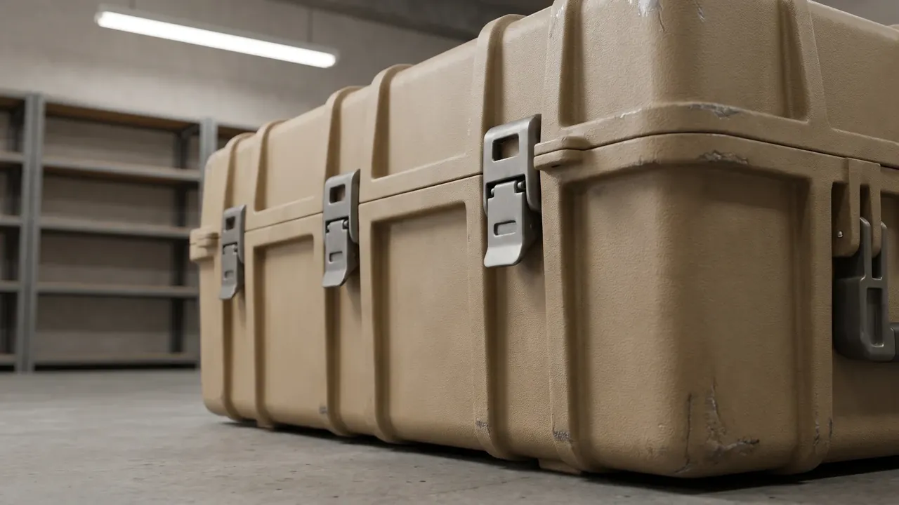
Lock selection must match the use scenario. Wafer and pin tumbler locks are simple and cost effective, suited to routine mis-opening prevention. Restricted keyway systems and high security cylinders raise resistance to technical opening, suiting sensitive scenarios. Mechanical combination locks support tiered multi-person management. Electronic and smart locks can log opening events and integrate with a ledger system, but must solve three problems: power supply, environmental tolerance and data security. Whichever option is chosen, the lock should form a single unit with the shell through a reinforced housing and anti-pry plate; a lock mounted only on a thin wall is limited by its weakest layer.
The tamper evident seal is the evidence layer of the access chain. Common forms include wire seals, plastic pull tight seals and label seals, each using a unique number for one item one code, leaving irreversible traces once opened. Four points govern management: seal numbers should correspond one to one with case numbers and loading records; seals should pass through the latch point with appropriate tension; appearance and numbers should be checked and countersigned by both parties at every handover; and procurement, issuance and destruction of seals should be logged. For handovers across organizations, composite seals combining visual features and electronic identification let manual and system checks verify each other. Consider the locking and structural practice described in military security case structures and GJB military standard case essentials.
Traceability Marking: RFID, Data Matrix and Asset Ledgers
Marking and traceability answer a chain of questions: whose case is this, what has it carried, where has it been, and where is it now. At the container engineering level, the implementation is to give each case a unique identity, keep the physical surface and the information system aligned, and ensure that alignment survives long service without peeling, wearing off or being misread.
Three carrier types typically hold identity information. The first is directly formed marking: numbers, batches and manufacturer information created in the mold, laser engraved or stamped into the shell. It is hard to remove and long lived, but fixed and not rewritable. The second is label carriers: QR codes and data matrix codes that are easy to scan into a system, but must solve weather resistance, abrasion resistance and anti-counterfeiting, usually with a protective layer or metal tag. The third is RFID labels, readable in batches without contact, well suited to warehouse inventory and fast in-out verification. Selection must address frequency band and read distance, performance degradation in metal environments, and how attachment affects sealing and shielding.
The three carriers are best combined rather than substituted. Formed marking provides the permanent base record, the QR code provides a human and mobile readable entry point, and RFID provides batch automation. At the system level, three things must be settled: coding rules must be unique and extensible without colliding with existing asset numbering; data fields must align with the ledger system, clarifying which information is fixed to the case and which is recorded per loading; and read-write permissions and data retention must meet confidentiality requirements. For export scenarios, marking content must also align with export packaging marking requirements so the case marking and the shipping marking do not contradict each other. See the coding and rollout practice in case asset QR code tracking.
Environmental Testing: Climate, Salt Fog, Vibration and Drop
Testing is the bridge from design to delivery and the only way to prove that protection capability actually exists. For this category, the test system is usually organized along four lines: climatic, corrosion, mechanical and sealing. Each line has its own standards, equipment and criteria, and all four should be fixed during design rather than added after the prototype is finished.
Climatic testing covers high temperature, low temperature, temperature cycling and damp heat cycling. It verifies material behavior across temperatures, gasket compression and rebound, insulation integrity, and whether internal marking fades or delaminates. Temperature cycling deserves special attention because it stresses both the thermal expansion loads on materials and the fatigue of sealing elements. Corrosion testing is represented by neutral salt fog, chiefly for sea transit and coastal warehousing, assessing the corrosion resistance of metal parts, fasteners and coatings while exposing galvanic corrosion risk at dissimilar metal contacts. Mechanical testing includes sinusoidal vibration, random vibration, mechanical shock and free drop, verifying cushioning and restraint, whether the locking structure stays closed under impact, and whether the shell cracks. Sealing tests use immersion, spray and pressure cycling to verify the joint behavior of the seal rating and the equalization valve.
A few practices are worth emphasizing. Test specimens should carry the actual liner, locks and marking, so that a bare shell test does not hide assembly related problems. Seal integrity should be rechecked both before and after testing, because many failures appear only afterwards. Temperature sequences are best run cold before hot, so structural damage from low temperature embrittlement can be observed. Test records should include equipment, parameters, specimen numbers and disposition of nonconformities, forming a traceable evidence chain. JUNZHIJIA typically treats the test list as part of the delivered documentation, submitted together with certification materials.
Certification and Documentation: UN Packaging, Export Controls and Checklists
Certification and documentation determine whether a container can legally enter cross-border circulation. This is not a technical detail; it is a precondition for the project to proceed. For specialized containers, the usual compliance dimensions include transport packaging certification, material and environmental compliance, and documentation related to export controls.
Transport packaging certification is the most critical item. Dangerous goods transport applies a full set of packaging requirements based on the United Nations recommendations on the transport of dangerous goods, confirming the safety of the package through performance tests such as drop, stack, air tightness and hydraulic tests, differentiated by content class and packing group. Note that this section addresses the certification path and document organization for the container as a package, not any determination of content properties. The applicable packing group and test items must follow local regulations, carrier requirements and the latest rules of the competent authority. The engineering role is to provide conforming design and test evidence against the class information supplied by the customer, not to make the classification decision on the customer's behalf.
Beyond transport certification, material compliance (flame retardance, low smoke, recyclability and hazardous substance restrictions), fumigation and heat treatment requirements for wood packaging, and export control lists and end use documentation are commonly involved. Three documentation mistakes recur: certifying only the prototype while ignoring batch consistency; preparing documents only in one language and stalling at the border; and treating marking, labels and accompanying documents as three unrelated systems with inconsistent information. A sound approach is to build one compliance checklist spanning design, testing, certification, marking and paperwork, assign an owner and status to each line, and run a cross functional review before delivery.
Palletization and Load Planning: Unitization, Stacking and Lifting
No matter how good an individual container is, a disorganized load plan will erode the real protection. Palletization and load planning handle the step from single case to unit: using standardized pallets, stacking schemes and securing methods to combine several cases into a stable, movable, verifiable transport unit.
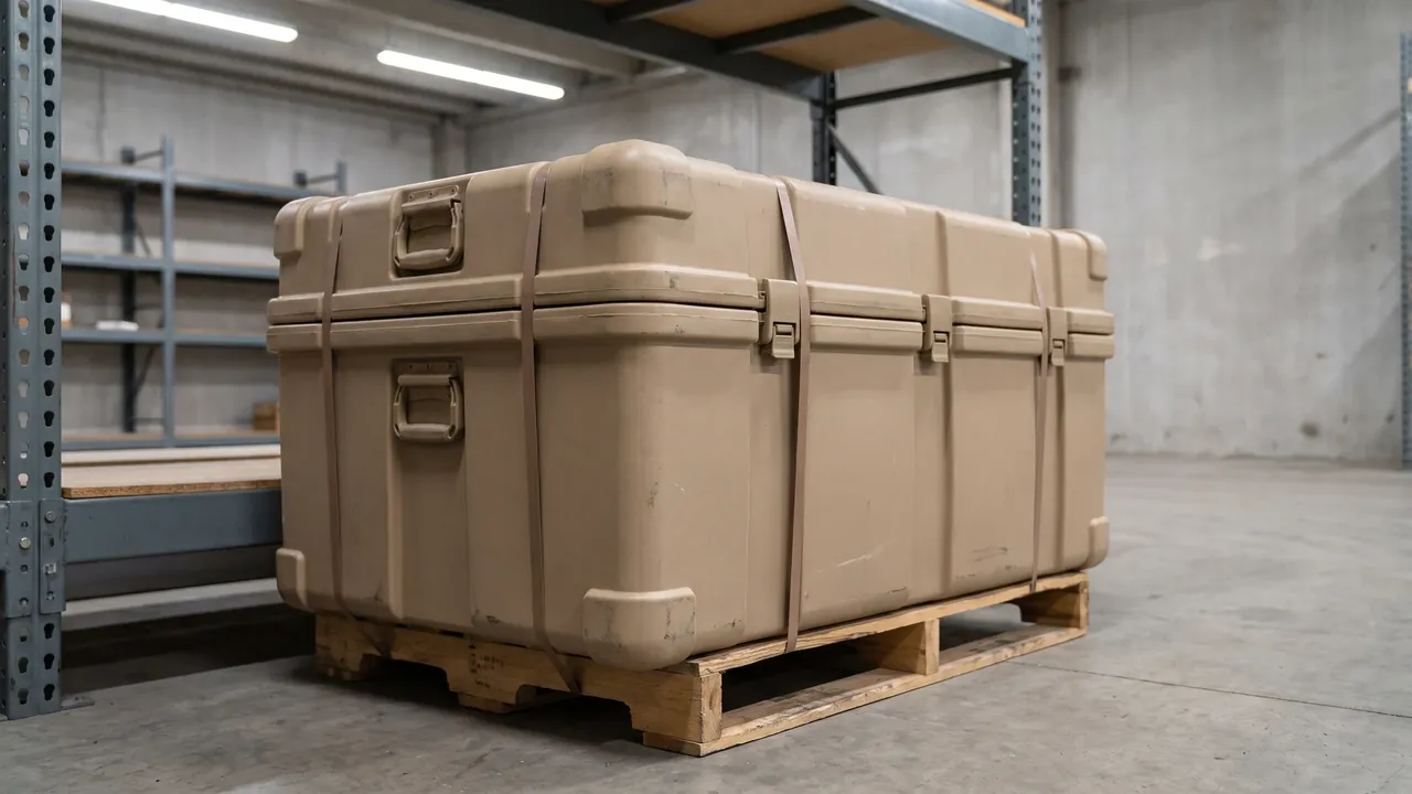
Pallet selection starts with matching case dimensions and mass. Pallet plan dimensions should relate to case base dimensions by whole numbers, avoiding unsupported corners that create uneven loading; the pallet load rating must cover the full stack mass with a safety margin; and heavy cases are better served by reinforced or steel pallets. The stacking scheme addresses both stability and loading. Stack heavy below and light above, aligning load paths through primary load bearing walls so upper loads pass through the walls rather than into the cavity, and add anti-slip pads or locating bosses between layers to prevent the stack shifting in transit.
Securing and lifting close out the plan. Stacks are usually secured with strapping, stretch wrap or edge protectors, and straps must avoid locks, valves and marking windows so they neither crush nor occlude them. Where lifting is required, the plan should state lifting points, sling angles and load calculations to avoid slings pinching the case sides. Stack height must also match warehouse conditions; use a method such as stacking load test practice to set a sensible limit. Once the stack is finished, verify the packing list against case marking to create a dispatch record where unit, case number and paperwork agree, which matters greatly for downstream traceability.
From the Manufacturer's Bench: Custom Flow, Acceptance and Selection Advice
From the manufacturer's viewpoint, custom work on specialized containers follows a fairly fixed chain: requirement clarification and technical agreement, protection matrix confirmation, structural and material design, prototype build, type testing and internal validation, customer acceptance and small batch confirmation, tooling and process freeze, volume production and in-process inspection, and delivery with documentation archiving. The most common failure point on that chain is not machining but incomplete requirements up front. If dimensions, environment, certification, marking and management requirements are not captured in one clear technical requirement document, rework costs multiply later.
Acceptance should focus on four areas. The first is structure and dimensions: shell wall thickness, rib locations, cavity dimensions and mounting hole positions against the drawing, usually controlled by sampling plus full inspection of critical dimensions. The second is material and batch: shell material, gaskets, liners, shielding layers, insulation and flame retardant materials should all have batch certificates and performance data, preventing hidden substitutions such as a thinner or lower grade alternative. The third is function and testing: sealing, pressure equalization, locking, marking and stacking should complete type validation before volume production, with routine sampling checks during production. The fourth is appearance and marking: serial numbers, labels and their positions and content should be verified piece by piece, and seals should reconcile with the ledger. See custom case acceptance and sampling for a related acceptance framework.
Selection advice reduces to three sentences. First, define the boundary before choosing the case: settle certification requirements and the regulatory chain before discussing structure and materials, so you do not build something that cannot ship. Second, rank by dimension rather than by price: order sealing, shielding, thermal control, damping and flame retardance by importance so the budget goes where it counts. Third, write verifiability into the contract: require test reports, material certificates and batch consistency statements, and put key metrics into acceptance clauses. For a side-by-side look at comparable military case engineering, see military protective case selection and EMI shielded military electronics cases to align the container approach with your own scenario.
Frequently Asked Questions (FAQ)
Q: What is the most fundamental difference between a special ordnance container and an ordinary protective case? A: The difference is not appearance or wall thickness but design objective and verification method. An ordinary ammunition box centers on capacity, handling convenience and basic protection, and is usually accepted on dimensions, appearance and a routine drop test. A special ordnance container serves sensitive material storage and transport, and every protection capability must be measurable, reproducible and traceable. Sealing needs leak rate data. Pressure equalization needs pressure cycle records. Shielding needs attenuation curves across a frequency band. Damping needs measured cavity acceleration. Locking and seals need to form a verifiable access evidence chain. In short, an ordinary crate delivers a box, while a special container delivers a documented body of protection evidence plus the box itself.
An ordinary case is judged by what it keeps out; a special container is judged by what it can prove. That difference should be visible in the paperwork from day one: a requirement matrix, a test plan, and a recorded result for every claim, so the delivered box arrives with its evidence rather than with promises.
Q: Why does a special container both seal tightly and fit a pressure equalisation valve? A: They are not contradictory; they are two sides of one system. Sealing aims to block liquid water, water vapor and dust. The equalization valve aims to release a differential pressure slowly when it appears, preventing the case from bulging, collapsing or crushing the gasket. Transit across climate zones, air transport and high altitude use all create meaningful differential pressure. Sealing without venting applies that pressure directly to the shell and gasket, which actually makes failure more likely. The correct approach is a waterproof breathable membrane that passes gas but not water, with the valve mounting hole protected by a gasket and a positive stop so the valve itself does not become a new leak point.
Engineer them as one system from the start: pick the sealing class for the environment, size the valve for the largest pressure swing the duty implies, and verify the pair with a cycling test rather than a calculation. Done properly, the case breathes without leaking and stays sealed without stress.
Q: Can static dissipation, grounding and electromagnetic shielding be handled in one case? A: Yes, but the paths must be clarified first. Static protection is about bleeding locally accumulated charge to a reference potential along a controlled path, emphasizing conductive materials and equipotential bonding. Electromagnetic shielding is about blocking electromagnetic coupling in and out, emphasizing electrical continuity and the treatment of seams and apertures. Grounding is the shared endpoint of both. The engineering approach unifies all three into one conductive network plus one grounding interface: interior walls, liners and fasteners are bonded into an equipotential whole, the shielding layer joins that network, and a marked grounding terminal leads it out. Take care not to break the path with coatings or anodized layers, and do not leave the liner as an isolated charged body.
Route each function deliberately: bonding and grounding as a defined path with measured resistance, shielding as a continuous conductive boundary with gasketed joints, and static dissipative surfaces wherever people actually touch. Keep the three paths documented on a drawing, because an undocumented conductive path is how one function quietly defeats another.
Q: Is a thermal insulation core genuinely useful, or is it just added weight? A: It depends entirely on the scenario. If the case must survive field storage with large day-night temperature swings, long transit with significant compartment temperature variation, or any requirement on the rate of internal temperature change, then passive insulation and thermal mass meaningfully slow the change and narrow the fluctuation band, making the internal environment more stable. If the case rotates entirely within a controlled temperature environment, the benefit is limited and the added material and mass reduce handling efficiency and stacking height. The way to decide is to define the allowed internal temperature band and duration, then run a holding test and measure the internal temperature curve against those targets rather than thickening insulation on intuition.
Specify the performance you need as a temperature curve and a duration, then ask the supplier to demonstrate it with instrumented testing of a loaded box rather than with material datasheets. Where the requirement is genuine, an insulated core plus phase-change or active elements is justified; where it is not, the weight is better spent on structure.
Q: Is choosing UL94 V-0 enough for flame retardance? A: V-0 is a screening starting point, not an endpoint. UL94 evaluates the combustion behavior of a material, and results depend heavily on specimen thickness and orientation. The same material can behave differently in a thin walled part than in a standard specimen, so the rated thickness must match the actual part thickness. For enclosed or semi-enclosed spaces, also consider smoke density and smoke toxicity, so that combustion does not produce dense smoke that hampers response. Structurally, prevent continuous fuel paths and melt drip paths. The sound approach combines combustion rating, low smoke and low toxicity, dripping behavior and structural measures into one requirement set, supported by material certificates and type test reports together.
Define the full fire scenario, including external flame, duration and what the contents must be protected from, then select materials and construction against that scenario and document the evidence chain. A rating on a datasheet is a component property; acceptance belongs to the assembly, tested as built.
Q: Tamper evident seals look simple. Why is the management requirement so demanding? A: Because the value of a seal comes almost entirely from verifiability rather than physical strength. A seal provides objective evidence of whether the case was opened, and that demands a complete evidence chain: seal numbers corresponding one to one with case numbers and loading records; seals passing through the designated point with proper tension; both parties checking numbers and countersigning at each handover; and procurement, issuance and destruction logged. If any link is missing, the seal degenerates into an ordinary cord. For handovers across organizations, use composite seals with both visual features and electronic identification so manual and system checks verify each other, reducing room for dispute.
Build the management system around the seal: define who applies it, who records the number, who verifies it at each node and what happens on a mismatch. The seal is only as strong as the record behind it, which is why serious users treat the register as a controlled document rather than a notebook.
Q: How should we choose marking and traceability — do we need both QR codes and serial numbers? A: You do not need everything, but a combination is better than a single choice. Formed marking, created in the mold or laser engraved, provides a permanent base record that is hard to remove and long lived, well suited to carrying case number and batch. A QR code provides a human and mobile readable entry point at low cost and fast rollout. RFID provides contactless batch reading for warehouse inventory and fast in-out verification, though its performance degrades in metal environments and needs dedicated selection and attachment. A workable combination is formed marking as the base record, QR codes as the human entry point, and RFID for batch automation, all under one coding rule and ledger field set that clarifies what is fixed to the case and what is recorded per loading.
Decide first what each identifier must do: a human-readable number for counting, a machine-readable code for speed, and a tamper-evident element for integrity. Combinations work best when each layer has a distinct job, and the mapping between the physical mark and the database record is written down and audited.
Q: Does passing type testing on the prototype mean the container is certified?
A: Not by itself. Type testing proves that a prototype met the targets under specified conditions, while certification usually also demands process capability and batch consistency: traceable raw material batches, controlled process parameters, routine sampling of critical dimensions and functions, and marking and paperwork matching the design requirements. The classic failure is a prototype that passes and a production batch that drifts, rooted in material substitution, process variation and missing inspection. A sound approach breaks certification requirements into five stages (design, testing, certification, marking, paperwork), assigns an owner and status to each, and runs a cross functional review before delivery. Note also that applicable certification categories and test items change as regulations evolve, so the latest rules of the competent authority and carrier must always be confirmed.
Related Reading